JP2005299580A - Control device for internal combustion engine - Google Patents
Control device for internal combustion engine Download PDFInfo
- Publication number
- JP2005299580A JP2005299580A JP2004119850A JP2004119850A JP2005299580A JP 2005299580 A JP2005299580 A JP 2005299580A JP 2004119850 A JP2004119850 A JP 2004119850A JP 2004119850 A JP2004119850 A JP 2004119850A JP 2005299580 A JP2005299580 A JP 2005299580A
- Authority
- JP
- Japan
- Prior art keywords
- knock
- data
- value
- correlation coefficient
- internal combustion
- Prior art date
- Legal status (The legal status is an assumption and is not a legal conclusion. Google has not performed a legal analysis and makes no representation as to the accuracy of the status listed.)
- Granted
Links
Images
Classifications
-
- F—MECHANICAL ENGINEERING; LIGHTING; HEATING; WEAPONS; BLASTING
- F02—COMBUSTION ENGINES; HOT-GAS OR COMBUSTION-PRODUCT ENGINE PLANTS
- F02D—CONTROLLING COMBUSTION ENGINES
- F02D35/00—Controlling engines, dependent on conditions exterior or interior to engines, not otherwise provided for
- F02D35/02—Controlling engines, dependent on conditions exterior or interior to engines, not otherwise provided for on interior conditions
- F02D35/027—Controlling engines, dependent on conditions exterior or interior to engines, not otherwise provided for on interior conditions using knock sensors
-
- G—PHYSICS
- G01—MEASURING; TESTING
- G01L—MEASURING FORCE, STRESS, TORQUE, WORK, MECHANICAL POWER, MECHANICAL EFFICIENCY, OR FLUID PRESSURE
- G01L23/00—Devices or apparatus for measuring or indicating or recording rapid changes, such as oscillations, in the pressure of steam, gas, or liquid; Indicators for determining work or energy of steam, internal-combustion, or other fluid-pressure engines from the condition of the working fluid
- G01L23/22—Devices or apparatus for measuring or indicating or recording rapid changes, such as oscillations, in the pressure of steam, gas, or liquid; Indicators for determining work or energy of steam, internal-combustion, or other fluid-pressure engines from the condition of the working fluid for detecting or indicating knocks in internal-combustion engines; Units comprising pressure-sensitive members combined with ignitors for firing internal-combustion engines
- G01L23/221—Devices or apparatus for measuring or indicating or recording rapid changes, such as oscillations, in the pressure of steam, gas, or liquid; Indicators for determining work or energy of steam, internal-combustion, or other fluid-pressure engines from the condition of the working fluid for detecting or indicating knocks in internal-combustion engines; Units comprising pressure-sensitive members combined with ignitors for firing internal-combustion engines for detecting or indicating knocks in internal combustion engines
- G01L23/225—Devices or apparatus for measuring or indicating or recording rapid changes, such as oscillations, in the pressure of steam, gas, or liquid; Indicators for determining work or energy of steam, internal-combustion, or other fluid-pressure engines from the condition of the working fluid for detecting or indicating knocks in internal-combustion engines; Units comprising pressure-sensitive members combined with ignitors for firing internal-combustion engines for detecting or indicating knocks in internal combustion engines circuit arrangements therefor
Landscapes
- Engineering & Computer Science (AREA)
- Chemical & Material Sciences (AREA)
- Combustion & Propulsion (AREA)
- Physics & Mathematics (AREA)
- General Physics & Mathematics (AREA)
- Mechanical Engineering (AREA)
- General Engineering & Computer Science (AREA)
- Combined Controls Of Internal Combustion Engines (AREA)
Abstract
【課題】 ノックセンサの出力から抽出したデータを統計的に処理する際に、少ないRAM容量で、データの平均値と標準偏差を演算できるようにする。
【解決手段】 点火毎にノックセンサ28の出力からノックの特徴を表す2つのデータ(ピーク値と形状相関係数)を求め、これら2つのデータをそれぞれなまし処理して各データの平均値を近似的に求めると共に、なまし処理前後のデータの偏差を二乗した値をなまし処理して近似的に分散Vを求め、この分散Vの平方根をとって近似的に標準偏差を求め、各データを平均値と標準偏差を用いて正規化する(ステップ102〜104)。そして、正規化した2つのデータに関する分布を求め、この分布と理想ノック分布との相関性を表すノック判定用相関係数を算出し、このノック判定用相関係数に基づいて1燃焼毎のノック判定に用いるノック判定閾値を補正する(ステップ105〜110)。
【選択図】 図2
PROBLEM TO BE SOLVED: To calculate an average value and a standard deviation of data with a small RAM capacity when statistically processing data extracted from an output of a knock sensor.
SOLUTION: For each ignition, two data (a peak value and a shape correlation coefficient) representing knock characteristics are obtained from the output of the knock sensor 28, and the average value of each data is obtained by smoothing these two data. The value obtained by approximating and the square of the deviation of the data before and after the annealing process is smoothed to obtain the variance V approximately, and the standard deviation is obtained approximately by taking the square root of the variance V. Is normalized using the average value and the standard deviation (steps 102 to 104). Then, a distribution related to the two normalized data is obtained, a knock determination correlation coefficient representing the correlation between this distribution and the ideal knock distribution is calculated, and a knock for each combustion is calculated based on the knock determination correlation coefficient. The knock determination threshold value used for determination is corrected (steps 105 to 110).
[Selection] Figure 2
Description
本発明は、内燃機関の運転状態を検出するセンサの出力を統計的に処理して内燃機関の運転状態を制御する内燃機関の制御装置に関する発明である。 The present invention relates to a control device for an internal combustion engine that statistically processes the output of a sensor that detects the operating state of the internal combustion engine to control the operating state of the internal combustion engine.
内燃機関の運転状態を制御する際に、内燃機関の運転状態を検出するセンサの出力を統計的に処理する必要がある場合がある。例えば、ノック判定においては、特公平6−60621号公報に記載されているように、点火毎にノックセンサの出力をサンプリングしてピーク値を抽出し、このピーク値を対数変換した値の分布の形状を統計的手法で解析してノック発生状態を判断し、ノック判定閾値を補正するようにしたものがある。
一般に、統計的手法でデータの分布形状を判断する指標として、平均値と標準偏差σが用いられることが多い。ここで、標準偏差σは、分散Vの平方根をとった値であり、データの散らばりの度合いを表す指標として広く用いられている。分散Vは、各データと平均値との偏差を二乗した値を合計し、その合計値をデータ数で割り算した値である。 In general, an average value and a standard deviation σ are often used as indices for determining the distribution shape of data by a statistical method. Here, the standard deviation σ is a value obtained by taking the square root of the variance V, and is widely used as an index representing the degree of data dispersion. The variance V is a value obtained by summing values obtained by squaring the deviation between each data and the average value and dividing the sum by the number of data.
例えば、n個のデータをX1 、X2 、……Xn とすると、平均値Xav、分散V、標準偏差σは次のように定義される。
平均値Xav=(X1 +X2 +……+Xn )/n
分散V={(X1 −Xav)2 +(X2 −Xav)2 +……+(Xn −Xav)2 }/n 標準偏差σ=√V
For example, when n pieces of data are X1, X2,... Xn, the average value Xav, variance V, and standard deviation σ are defined as follows.
Average value Xav = (X1 + X2 + ...... + Xn) / n
Variance V = {(X1 -Xav) 2 + (X2 -Xav) 2 + ... + (Xn -Xav) 2 } / n Standard deviation σ = √V
これら各定義式を用いて平均値Xavと標準偏差σを演算する場合、所定期間分の多数のデータを格納する膨大なRAM容量が必要となる。エンジン制御のように、各気筒の点火毎、燃料噴射毎等に各種の情報を更新していく必要があるシステムでは、平均値Xavと標準偏差σの演算に使用できるRAM容量も制限されるため、各定義式を用いる演算方法をそのまま実施することは現実には困難である。 When calculating the average value Xav and the standard deviation σ using each of these defining formulas, a huge RAM capacity for storing a large amount of data for a predetermined period is required. In a system in which various information needs to be updated for each cylinder ignition, fuel injection, etc., as in engine control, the RAM capacity that can be used to calculate the average value Xav and the standard deviation σ is also limited. In practice, it is difficult to implement the calculation method using each definition formula as it is.
また、エンジンの運転条件が変化すると、ノックセンサの出力やそのピーク値も変化するため、RAMにピーク値のデータを蓄えている途中で運転条件が変化すると、複数の運転条件が混在した平均値Xavと標準偏差σを演算してしまい、平均値Xavと標準偏差σの精度が悪化するという問題がある。つまり、各定義式を用いる演算方法では、過渡状態で平均値Xavと標準偏差σの追従性が悪いという問題がある。 In addition, if the engine operating conditions change, the knock sensor output and its peak value also change. Therefore, if the operating conditions change while the peak value data is stored in the RAM, an average value in which a plurality of operating conditions coexist. There is a problem that Xav and standard deviation σ are calculated, and the accuracy of average value Xav and standard deviation σ deteriorates. That is, the calculation method using each definition formula has a problem that the followability of the average value Xav and the standard deviation σ is poor in a transient state.
そこで、上記特許文献1では、ノックセンサの出力のピーク値を対数変換した値の分布の形状を判断する際に、平均値Xavと標準偏差σを演算せずに、分布の累積10%点、50%点、累積90%点を点火毎に更新して、これらの累積10%点、50%点、累積90%点の比からノック発生状態を判断するようにしている。
Therefore, in
この累積%点を用いて平均値Xavと標準偏差σを近似的に演算することは可能であるが、ノック発生時の特徴が大きく現れるのは、分布の上位累積数%点(例えば累積97%点)であるため、ノック発生時の特徴を平均値Xavと標準偏差σの演算値に反映させるためには、上位累積数%点(例えば累積97%点)を用いて平均値Xavと標準偏差σを演算する必要がある。しかし、ノック発生頻度が同一でも、ノックの大きさ(ピーク値の大きさ)のばらつき範囲が大きいため、上位累積数%点が大きくずれる傾向がある。このため、上位累積%点を用いて平均値Xavと標準偏差σを演算したのでは、上位累積数%点のばらつきによって平均値Xavと標準偏差σの演算値がそれぞれの真値に対して大きくずれてしまう可能性が高い。 Although it is possible to approximately calculate the average value Xav and the standard deviation σ using this cumulative percentage point, the characteristic at the time of occurrence of knocking is that the upper cumulative percentage point (for example, cumulative 97%) of the distribution. Therefore, in order to reflect the characteristics at the time of occurrence of the knock in the calculated value of the average value Xav and the standard deviation σ, the average value Xav and the standard deviation are calculated using the upper cumulative several percentage points (for example, the cumulative 97% point). It is necessary to calculate σ. However, even if the knock occurrence frequency is the same, since the variation range of the knock magnitude (peak value magnitude) is large, the upper cumulative percentage point tends to deviate greatly. For this reason, when the average value Xav and the standard deviation σ are calculated using the upper cumulative% point, the calculated values of the average value Xav and the standard deviation σ are larger than the true values due to variations in the upper cumulative several percentage points. There is a high possibility of shifting.
本発明はこのような事情を考慮してなされたものであり、従ってその目的は、内燃機関の運転状態を検出するセンサの出力を周期的にサンプリングして統計的に処理する際に、少ないRAM容量で、データの平均値と該データの散らばりの度合いを表す指標を精度良く近似的に演算することができると共に、過渡状態での追従性を向上させることができる内燃機関の制御装置を提供することにある。 The present invention has been made in view of such circumstances. Therefore, the object of the present invention is to reduce the amount of RAM when the output of the sensor for detecting the operating state of the internal combustion engine is periodically sampled and statistically processed. Provided is a control device for an internal combustion engine capable of calculating an average value of data and an index representing the degree of dispersion of the data with a capacity and approximately accurately and improving followability in a transient state. There is.
上記目的を達成するために、請求項1に係る発明は、内燃機関の運転状態を検出するセンサの出力を周期的にサンプリングして統計的に処理する統計処理手段を備え、この統計処理手段の処理結果を用いて内燃機関の運転を制御する内燃機関の制御装置において、前記統計処理手段によって、前記センサ出力のサンプリング毎に該データをなまし処理して近似的に該データの平均値を求め、このなまし処理前後のデータの偏差を二乗した値を用いて該データの散らばりの度合いを表す指標(以下「データ散らばり度合い指標」という)を演算するようにしたものである。本発明のように、なまし処理を用いれば、センサ出力のサンプリング毎に平均値とデータ散らばり度合い指標を逐次更新できるため、多数のデータを車載コンピュータのRAMに記憶し続ける必要がなくなり、少ないRAM容量で、平均値とデータ散らばり度合い指標を近似的に演算することができる。しかも、上位累積数%点を用いないため、分布の上位ばらつきの影響を受けずに、平均値とデータ散らばり度合い指標を演算することができて、平均値とデータ散らばり度合い指標の近似精度を向上させることができる。更に、なまし処理を用いることで、過渡状態での追従性も向上させることができる。
In order to achieve the above object, the invention according to
ここで、データ散らばり度合い指標としては、例えば分散Vや標準偏差σが考えられる。前述した定義式によれば、平均値は、全てのデータを相加平均した値であり、分散Vは、各データ毎に求めた(データ−平均値)2 を相加平均した値であり、標準偏差σ=√Vである。 Here, as the data dispersion degree index, for example, the variance V and the standard deviation σ can be considered. According to the above-described definition formula, the average value is a value obtained by arithmetically averaging all data, and the variance V is a value obtained by arithmetically averaging (data-average value) 2 obtained for each data. Standard deviation σ = √V.
本発明のように、平均値(データの相加平均値)をデータのなまし処理値で近似する方法を、分散V[(データ−平均値)2 の相加平均値]の演算方法に応用すれば、分散V[(データ−平均値)2 の相加平均]は、(データ−平均値)2 のなまし処理値で近似できることが分かる。本発明では、平均値をデータのなまし処理値で近似するため、(データ−平均値)2 は、なまし処理前後のデータの偏差を二乗した値となる。 As in the present invention, a method of approximating an average value (arithmetic mean value of data) with a data smoothing processing value is applied to a method of calculating variance V [(arithmetic mean value of (data−average value) 2 ]]. Then, it can be seen that the variance V [arithmetic average of (data−average value) 2 ] can be approximated by the smoothed processing value of (data−average value) 2 . In the present invention, since the average value is approximated by the data smoothing process value, (data-average value) 2 is a value obtained by squaring the deviation of the data before and after the smoothing process.
従って、請求項2のように、なまし処理前後のデータの偏差を二乗した値をなまし処理して近似的に分散Vを求め、この分散Vの平方根を演算して近似的に標準偏差σを求めるようにすると良い。このようにすれば、なまし処理によって平均値と標準偏差σの両方を簡単に演算することができる。
Therefore, as in
更に、請求項3のように、正規化手段により、データを平均値と標準偏差σを用いて正規化(標準化、無次元化)するようにすると良い。このようにすれば、運転条件が変化しても、その前後にサンプリングしたデータを、いずれも標準的な運転条件下でのデータに補正することができる。これにより、運転条件毎に区分してデータを統計処理する必要がなくなり、統計処理の負荷を軽減できると共に、運転条件の変化による統計処理精度の低下を回避することができる。
Further, as in
本発明をノック判定に適用する場合は、請求項4のように、内燃機関のノック状態に応じた波形の信号を出力するセンサの出力のサンプリング毎に該センサ出力のノック周波数成分のピーク値と、該センサ出力の波形とノック特有の波形を表す理想ノック波形との相関性を表す形状相関係数とを前記データとして求めて、これらピーク値と形状相関係数をそれぞれ前記正規化手段により正規化し、正規化したピーク値と形状相関係数に関する所定点火回数分の分布を求め、この分布の形状がノック発生時に現れる特徴を有するか否かでノックの発生状態を判定するようにすると良い。このようにすれば、センサ出力からノックの特徴を表す2つのデータ(ピーク値と形状相関係数)を求めてこれら2つのデータを正規化して所定点火回数分の分布を求めるようにしているため、前記特許文献1のようにセンサ出力のピーク値のみの分布とは異なり、ノイズとノックとを区別できる分布を作成することができ、ノイズによるノック判定精度の悪化の問題を解決できて、ノック判定の精度・信頼性を向上させることができる。しかも、2つのデータ(ピーク値と形状相関係数)を正規化して、正規化データの分布を求めるので、運転条件による差を無くした普遍的な分布を作成することができ、運転条件毎に分布を作成する必要がなくなり、分布作成の処理負荷を軽減できると共に、運転条件による分布の精度低下を回避することができる。
When the present invention is applied to knock determination, the peak value of the knock frequency component of the sensor output is sampled for each sampling of the output of the sensor that outputs a signal having a waveform corresponding to the knock state of the internal combustion engine. The shape correlation coefficient representing the correlation between the sensor output waveform and the ideal knock waveform representing the knock-specific waveform is obtained as the data, and the peak value and the shape correlation coefficient are respectively normalized by the normalizing means. It is preferable to obtain a distribution corresponding to a predetermined number of ignition times related to the normalized peak value and the shape correlation coefficient, and to determine the knock occurrence state based on whether or not the shape of this distribution has a feature that appears when the knock occurs. In this way, two data (a peak value and a shape correlation coefficient) representing knock characteristics are obtained from the sensor output, and these two data are normalized to obtain a distribution for a predetermined number of ignition times. Unlike the distribution of only the peak value of the sensor output as in the above-mentioned
また、請求項5のように、なまし処理に用いるなまし係数を内燃機関の運転状態に応じて変化させるようにしても良い。このようにすれば、例えば、定常運転時には、平均値、標準偏差σ等の正確性を重視した設定にし、過渡運転時には、追従性を重視した設定にするといった具合に、内燃機関の運転状態に応じて、正確性や追従性を調整できる利点がある。
Further, as in
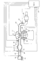
以下、本発明をノック判定処理に適用した一実施例を説明する。まず、図1に基づいてエンジン制御システム全体の概略構成を説明する。内燃機関であるエンジン11の吸気管12の最上流部には、エアクリーナ13が設けられ、このエアクリーナ13の下流側に、吸入空気量を検出するエアフローメータ14が設けられている。このエアフローメータ14の下流側には、モータ10によって開度調節されるスロットルバルブ15とスロットル開度を検出するスロットル開度センサ16とが設けられている。
Hereinafter, an embodiment in which the present invention is applied to knock determination processing will be described. First, a schematic configuration of the entire engine control system will be described with reference to FIG. An
更に、スロットルバルブ15の下流側には、サージタンク17が設けられ、このサージタンク17には、吸気管圧力を検出する吸気管圧力センサ18が設けられている。また、サージタンク17には、エンジン11の各気筒に空気を導入する吸気マニホールド19が設けられ、各気筒の吸気マニホールド19の吸気ポート近傍に、それぞれ燃料を噴射する燃料噴射弁20が取り付けられている。また、エンジン11のシリンダヘッドには、各気筒毎に点火プラグ21が取り付けられ、各点火プラグ21の火花放電によって筒内の混合気に着火される。
Further, a
一方、エンジン11の排気管22には、排出ガス中のCO,HC,NOx等を浄化する三元触媒等の触媒23が設けられ、この触媒23の上流側に、排出ガスの空燃比を検出する空燃比センサ24が設けられている。また、エンジン11のシリンダブロックには、冷却水温を検出する冷却水温センサ25と、ノック振動を検出するノックセンサ28と、エンジン11のクランク軸が所定クランク角回転する毎にパルス信号を出力するクランク角センサ26が取り付けられている。このクランク角センサ26の出力信号に基づいてクランク角やエンジン回転速度が検出される。
On the other hand, the
これら各種センサの出力は、エンジン制御回路(以下「ECU」と表記する)27に入力される。このECU27は、マイクロコンピュータを主体として構成され、内蔵されたROM(記憶媒体)に記憶された各種のエンジン制御プログラムを実行することで、燃料噴射弁20の燃料噴射量や点火プラグ21の点火時期を制御する。
Outputs of these various sensors are input to an engine control circuit (hereinafter referred to as “ECU”) 27. The
更に、このECU27は、後述する図2乃至図4のノック判定用の各ルーチンを実行することで、点火毎にノックセンサ28の出力(以下単に「センサ出力」という)からノックの特徴を表す2つのデータ(ピーク値と形状相関係数)を抽出し、これら2つのデータをそれぞれなまし処理して各データの平均値を近似的に求めると共に、なまし処理前後のデータの偏差を二乗した値をなまし処理して近似的に分散Vを求め、この分散Vの平方根を演算して近似的に標準偏差σを求める。その後、ECU27は、各データを平均値と標準偏差σを用いて正規化(標準化、無次元化)して、正規化したピーク値と形状相関係数に関する所定点火回数分の分布を求め、この分布と理想ノック分布との相関性(類似性)を表すノック判定用の相関係数(類似度)をノックレベル(ノック発生頻度)を表す指標として算出し、このノック判定用の相関係数に基づいて1燃焼毎のノック判定に用いるノック判定閾値を補正する。そして、ECU27は、1燃焼毎にセンサ出力のノック周波数成分のピーク値(又は所定区間のノック周波数成分の積分値等)を前記ノック判定閾値と比較して1燃焼毎にノックの有無を判定し、ノック有りと判定したときに点火時期を遅角補正してノックを抑制し、ノック無しの状態が続いたときに点火時期を進角補正するというノック制御を行うことで、聴感で許容できるノック音の範囲内で点火時期を進角させてエンジン出力や燃費を向上させるようにしている。
以下、このノック判定の方法について詳しく説明する。
Further, the
Hereinafter, this knock determination method will be described in detail.
(1)センサ出力から抽出するデータ
センサ出力から抽出するデータは、ノックの特徴を表すデータである。本実施例では、このデータとして、センサ出力のノック周波数成分のピーク値と、該センサ出力の波形とノック特有の波形を表す理想ノック波形との相関性を表す形状相関係数を用いる。この形状相関係数の演算は、次のようにして行う。まず、ピーク前後の所定期間の理想的なノック波形を理想ノック波形として定め、ピーク前のセンサ出力波形については理想ノック波形より上昇率が急峻であれば理想ノック波形をそのまま積算してピーク前の波形面積を求め、理想ノック波形より上昇率が緩やかであれば、センサ出力波形と理想ノック波形との差に応じて、理想ノック波形に対して所定量小さく補正した値を積算してピーク前の波形面積を求める。
(1) Data extracted from sensor output Data extracted from sensor output is data representing the characteristics of knock. In this embodiment, a shape correlation coefficient representing the correlation between the peak value of the knock frequency component of the sensor output and the ideal knock waveform representing the knock-specific waveform is used as this data. The calculation of the shape correlation coefficient is performed as follows. First, an ideal knock waveform for a predetermined period before and after the peak is determined as an ideal knock waveform.If the rate of increase in the sensor output waveform before the peak is steeper than the ideal knock waveform, the ideal knock waveform is integrated as it is before the peak. If the waveform area is obtained and the rate of increase is slower than the ideal knock waveform, the corrected value smaller than the ideal knock waveform by a predetermined amount is integrated according to the difference between the sensor output waveform and the ideal knock waveform. Determine the waveform area.
ピーク後の波形面積については、ピーク後のセンサ出力波形と理想ノック波形との差に応じて理想ノック波形に対して小さく補正した値を積算してピーク後の波形面積を求める。このようにして、ピーク前・後の波形面積の演算が終了したら、ピーク前・後の波形面積を合計してピーク前後の所定期間の波形面積を求め、この波形面積を理想ノック波形の面積で割り算した値を形状相関係数とする。 As for the waveform area after the peak, the waveform area after the peak is obtained by integrating the values corrected to be smaller with respect to the ideal knock waveform according to the difference between the sensor output waveform after the peak and the ideal knock waveform. When the calculation of the waveform area before and after the peak is completed in this way, the waveform areas before and after the peak are summed to obtain the waveform area for a predetermined period before and after the peak, and this waveform area is calculated by the area of the ideal knock waveform. The divided value is used as the shape correlation coefficient.
(2)データの正規化
各データ(ピーク値と形状相関係数)を正規化するには、平均値と標準偏差σが必要となり、標準偏差σを算出するには、分散Vが必要となる。
例えば、n個のデータをX1 、X2 、……Xn とすると、平均値Xav、分散V、標準偏差σは次のように定義される。
(2) Normalization of data To normalize each data (peak value and shape correlation coefficient), an average value and a standard deviation σ are required, and a variance V is required to calculate the standard deviation σ. .
For example, when n pieces of data are X1, X2,... Xn, the average value Xav, the variance V, and the standard deviation σ are defined as follows.
平均値Xav=(X1 +X2 +……+Xn )/n
分散V={(X1 −Xav)2 +(X2 −Xav)2 +……+(Xn −Xav)2 }/n 標準偏差σ=√V
これら各定義式を用いて平均値Xavと標準偏差σを演算する場合、所定期間分の多数のデータを格納する膨大なRAM容量が必要となる。エンジン制御のように、各気筒の点火毎、燃料噴射毎等に各種の情報を更新していく必要があるシステムでは、平均値Xavと標準偏差σの演算に使用できるRAM容量も制限されるため、各定義式を用いる演算方法をそのまま実施することは現実には困難である。
Average value Xav = (X1 + X2 + ...... + Xn) / n
Variance V = {(X1 -Xav) 2 + (X2 -Xav) 2 + ... + (Xn -Xav) 2 } / n Standard deviation σ = √V
When calculating the average value Xav and the standard deviation σ using each of these defining formulas, a huge RAM capacity for storing a large amount of data for a predetermined period is required. In a system in which various information needs to be updated for each cylinder ignition, fuel injection, etc., as in engine control, the RAM capacity that can be used to calculate the average value Xav and the standard deviation σ is also limited. In practice, it is difficult to implement the calculation method using each definition formula as it is.
そこで、本実施例では、センサ出力からデータを抽出する毎に、該データをなまし処理して近似的に該データの平均値を求めると共に、このなまし処理前後のデータの偏差を二乗した値を用いて標準偏差σを近似的に求める。 Therefore, in this embodiment, every time data is extracted from the sensor output, the data is smoothed to obtain an average value of the data, and a value obtained by squaring the deviation of the data before and after the smoothing process. Is used to approximately obtain the standard deviation σ.
前述した定義式によれば、平均値は、全てのデータを相加平均した値であり、分散Vは、各データ毎に求めた(データ−平均値)2 を相加平均した値であり、標準偏差σ=√Vである。本実施例のように、平均値(データの相加平均値)をデータのなまし処理値で近似する方法を、分散V[(データ−平均値)2 の相加平均値]の演算方法に応用すれば、分散V[(データ−平均値)2 の相加平均]は、(データ−平均値)2 のなまし処理値で近似できることが分かる。本実施例では、平均値をデータのなまし処理値で近似するため、(データ−平均値)2 は、なまし処理前後のデータの偏差を二乗した値となる。この関係から、本実施例では、なまし処理前後のデータの偏差を二乗した値をなまし処理して近似的に分散Vを求め、この分散Vの平方根を演算して近似的に標準偏差σを求める。 According to the above-described definition formula, the average value is a value obtained by arithmetically averaging all data, and the variance V is a value obtained by arithmetically averaging (data-average value) 2 obtained for each data. Standard deviation σ = √V. A method of approximating an average value (arithmetic average value of data) with a data smoothing processing value as in this embodiment is an arithmetic method of variance V [(arithmetic average value of (data−average value) 2 ]]. When applied, it can be seen that the variance V [arithmetic average of (data-average value) 2 ] can be approximated by the smoothed processing value of (data-average value) 2 . In this embodiment, since the average value is approximated by the data smoothing process value, (data-average value) 2 is a value obtained by squaring the deviation of the data before and after the smoothing process. From this relationship, in this embodiment, the value obtained by squaring the deviation of the data before and after the annealing process is approximated to obtain the variance V approximately, and the square root of this variance V is calculated to approximate the standard deviation σ. Ask for.
以上のようにして、ピーク値と形状相関係数についてそれぞれ平均値と標準偏差σをなまし処理によって演算する毎に、この平均値と標準偏差σを用いてピーク値と形状相関係数を次式により正規化(標準化、無次元化)する。
正規化ピーク値Sp =(ピーク値−ピーク値平均値)/ピーク値標準偏差
正規化形状相関係数Sc
=(形状相関係数−形状相関係数平均値)/形状相関係数標準偏差
この正規化により、運転条件による差を無くした普遍的なデータ(ピーク値と形状相関係数)を求めることができる。
As described above, every time the average value and the standard deviation σ are calculated by the smoothing process for the peak value and the shape correlation coefficient, the peak value and the shape correlation coefficient are calculated using the average value and the standard deviation σ. Normalize (standardize, dimensionless) by formula.
Normalized peak value Sp = (peak value−peak value average value) / peak value standard deviation normalized shape correlation coefficient Sc
= (Shape correlation coefficient-Shape correlation coefficient average value) / Shape correlation coefficient standard deviation By this normalization, universal data (peak value and shape correlation coefficient) that eliminates the difference due to operating conditions can be obtained. it can.
(3)検出分布の作成
ピーク値と形状相関係数との正規化データ(Sp ,Sc )が、予め区分された複数の領域の何処に該当するか判断し、該当した領域のカウンタをカウントアップする。この処理を所定点火回数分繰り返すことで検出分布を作成する。
(3) Creation of detection distribution It is determined where the normalized data (Sp, Sc) of the peak value and the shape correlation coefficient corresponds to a plurality of areas divided in advance, and the counter of the corresponding area is counted up. To do. The detection distribution is created by repeating this process for a predetermined number of times of ignition.
この際、検出分布が存在する可能性のある全ての領域を細かく区分して各領域毎にカウンタを設けて検出分布を作成するようにしても良いが、この場合には、カウンタの数が多くなり過ぎてECU27のRAM使用量が多くなり過ぎる欠点がある。
At this time, it is possible to finely divide all the areas where the detection distribution may exist and provide a counter for each area to create the detection distribution. However, in this case, the number of counters is large. There is a drawback that the amount of RAM used by the
そこで、本実施例では、検出分布が存在する可能性のある領域の中からノックの特徴が顕著に現れる少数の領域(以下「特徴領域」という)を抽出し、各特徴領域毎にカウンタを設け、点火毎にピーク値と形状相関係数の正規化データ(Sp ,Sc )が属する特徴領域のカウンタをカウントアップすることで、正規化データ(Sp ,Sc )の分布を求める。このようにすれば、ノックの特徴が顕著に現れる少数の特徴領域のみの正規化データ(Sp ,Sc )をカウントするだけで良いため、RAM使用量を大幅に節約できるという利点がある。しかも、ノックの特徴が顕著に現れる部分のみを選択して抽出できるため、ノック判定の精度・信頼性も十分に確保することができる。
(4)検出分布と理想ノック分布との相関性(ノックレベルの判定)
正規化データ(Sp ,Sc )による検出分布と理想ノック分布との相関性(類似性)を表すノック判定用の相関係数(類似度)を演算する。このノック判定用の相関係数は、検出分布の形状がノック発生時に現れる特徴を有するか否かを判定する指標となる。
Therefore, in this embodiment, a small number of areas where knock characteristics are noticeable (hereinafter referred to as “feature areas”) are extracted from the areas where the detection distribution may exist, and a counter is provided for each feature area. Then, the distribution of the normalized data (Sp, Sc) is obtained by counting up the counter of the feature region to which the normalized data (Sp, Sc) of the peak value and the shape correlation coefficient belongs every ignition. In this way, it is only necessary to count the normalized data (Sp, Sc) of only a small number of feature regions in which knock features are noticeable, so that there is an advantage that the amount of RAM used can be greatly saved. In addition, since only the portion where the knock characteristic appears noticeably can be selected and extracted, the accuracy and reliability of the knock determination can be sufficiently ensured.
(4) Correlation between detection distribution and ideal knock distribution (knock level determination)
A correlation coefficient (similarity) for knock determination representing the correlation (similarity) between the detection distribution based on the normalized data (Sp, Sc) and the ideal knock distribution is calculated. This correlation coefficient for knock determination serves as an index for determining whether or not the shape of the detection distribution has a feature that appears when a knock occurs.
ここで、理想ノック分布は、予め許容レベルを越えるノックが発生しているときに上記方法で演算された正規化データ(Sp ,Sc )の分布であり、ECU27のROM等の不揮発性メモリに記憶されている。ノック判定用の相関係数は、検出分布のパターンと理想ノック分布のパターンの内積をノルムの積で割って求める。ノルムの積で割ることで、ノック判定用の相関係数の絶対値は常に1以下(−1≦ノック判定用相関係数≦1)になり、検出分布と理想ノック分布との相関性が高いほど、ノック判定用の相関係数は1に近い値になる。従って、ノック判定用の相関係数は、ノックレベル(ノック発生頻度)を表す指標となり、ノック判定用の相関係数が1に近い値になるほど、ノックレベルが大きい(ノック発生頻度が高い)と判定することができる。
Here, the ideal knock distribution is a distribution of normalized data (Sp, Sc) calculated by the above method when a knock exceeding an allowable level has occurred in advance, and is stored in a nonvolatile memory such as a ROM of the
(5)ノック判定閾値の補正
ノック判定用の相関係数を予め設定した判定値と比較し、このノック判定用の相関係数が判定値以上であれば、許容レベルを越えるノックが発生していると判断して、1燃焼毎のノック判定に用いるノック判定閾値を小さくするよう補正する。これにより、より小さなノックを検出できるようにする。
(5) Correction of knock determination threshold The correlation coefficient for knock determination is compared with a predetermined determination value. If the correlation coefficient for knock determination is equal to or greater than the determination value, knock exceeding the allowable level occurs. Therefore, the knock determination threshold value used for knock determination for each combustion is corrected to be small. This makes it possible to detect smaller knocks.
反対に、ノック判定用の相関係数が判定値よりも小さければ、ノックレベルが許容レベルを下回っていると判断する。この場合は、ノック制御により点火時期を必要以上に遅角させて、エンジントルクを低下させている可能性があるため、より大きなノックのみを検出するように、ノック判定閾値を大きくするよう補正する。尚、ノック判定用の相関係数が適正なノック状態に相当する所定範囲内に収まっているときには、ノック判定閾値を補正しないようにしても良い。 On the other hand, if the correlation coefficient for knock determination is smaller than the determination value, it is determined that the knock level is below the allowable level. In this case, since the ignition timing may be retarded more than necessary by knock control to reduce the engine torque, correction is performed to increase the knock determination threshold so that only larger knocks are detected. . When the correlation coefficient for knock determination is within a predetermined range corresponding to an appropriate knock state, the knock determination threshold value may not be corrected.
このような処理により、製造ばらつきや経年変化による振動レベルの変化に追従してノック判定閾値を自動的に補正することができるため、常に適正なノック判定閾値を使用して精度の良いノック判定を行うことができると共に、設計・開発技術者がノック判定閾値を適合する際に、製造ばらつきや経年変化の影響を詳細に検討する必要がなくなり、ノック判定閾値の適合作業を簡略化できるという利点もある。
以上説明したノック判定閾値の補正は、ECU27によって図2乃至図4の各ルーチンに従って実行される。以下、これら各ルーチンの処理内容を説明する。
By such processing, the knock determination threshold can be automatically corrected following changes in the vibration level due to manufacturing variations and aging, so accurate knock determination is always performed using an appropriate knock determination threshold. In addition, the design / development engineer can eliminate the need for detailed examination of the effects of manufacturing variations and changes over time when adapting the knock determination threshold, and the work of adapting the knock determination threshold can be simplified. is there.
The correction of the knock determination threshold described above is executed by the
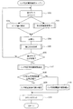
[ノック判定閾値補正ルーチン]
図2のノック判定閾値補正ルーチンは、エンジン運転中に周期的に実行される。本ルーチンが起動されると、まずステップ101で、センサ出力から抽出したデータ(ピーク値Pと形状相関係数C)のサンプリング数をカウントする総カウンタをカウントアップし、点火毎にセンサ出力のノック周波数成分のピーク値Pを検出すると共に(ステップ102)、後述する図3の形状相関係数算出ルーチンを実行して、形状相関係数Cを算出する(ステップ103)。
[Knock determination threshold correction routine]
The knock determination threshold value correction routine of FIG. 2 is periodically executed during engine operation. When this routine is started, first, in
この後、ステップ104に進み、後述する図4の正規化ルーチンを実行して、ピーク値Pと形状相関係数Cについて、それぞれ平均値と標準偏差σをなまし処理によって演算して平均値と標準偏差σを用いてデータを正規化(標準化、無次元化)する。この後、ステップ105に進み、検出分布作成ルーチン(図示せず)を実行して、次のようにして検出分布を作成する。本実施例では、検出分布が存在する可能性のある領域の中からノックの特徴が顕著に現れる少数の領域(特徴領域)を抽出し、各特徴領域毎にカウンタを設ける。そして、ピーク値Pと形状相関係数Cの正規化データ(Sp ,Sc )がいずれかの特徴領域に該当するか否かを判定し、該当する特徴領域があれば、その特徴領域のカウンタをカウントアップし、該当する特徴領域がなければ、いずれの特徴領域のカウンタもカウントアップしない。 Thereafter, the routine proceeds to step 104, where the normalization routine of FIG. 4 described later is executed, and the average value and the standard deviation σ are calculated by averaging processing for the peak value P and the shape correlation coefficient C, respectively. Data is normalized (standardized, dimensionless) using the standard deviation σ. Thereafter, the process proceeds to step 105, where a detection distribution creation routine (not shown) is executed to create a detection distribution as follows. In the present embodiment, a small number of regions (feature regions) in which knock features are prominent are extracted from regions in which a detection distribution may exist, and a counter is provided for each feature region. Then, it is determined whether the normalized data (Sp, Sc) of the peak value P and the shape correlation coefficient C corresponds to any feature region. If there is a corresponding feature region, a counter of the feature region is determined. If there is no corresponding feature area, the counter of any feature area is not counted up.
この後、ステップ106に進み、総カウンタの値が所定値に達したか否かを判定し、総カウンタの値が所定値に達していなければ、上記ステップ101〜105の処理を繰り返す。これにより、ピーク値Pと形状相関係数Cのサンプリング数がそれぞれ所定値になるまで、ピーク値Pと形状相関係数Cのサンプリングと、それらのデータの正規化と、検出分布作成の処理を繰り返す。
Thereafter, the process proceeds to step 106, where it is determined whether or not the value of the total counter has reached a predetermined value. If the value of the total counter has not reached the predetermined value, the processes of
そして、総カウンタの値が所定値に達した時点で、ステップ107に進み、ノック判定用相関係数算出ルーチン(図示せず)を実行して、正規化データ(Sp ,Sc )による検出分布と理想ノック分布との相関性を表すノック判定用の相関係数を算出する。このノック判定用の相関係数は、正規化データ(Sp ,Sc )による検出分布のパターンと理想ノック分布のパターンの内積をノルムの積で割って求める。 When the value of the total counter reaches a predetermined value, the routine proceeds to step 107, where a knock determination correlation coefficient calculation routine (not shown) is executed, and the detection distribution based on the normalized data (Sp, Sc) A correlation coefficient for knock determination representing the correlation with the ideal knock distribution is calculated. The correlation coefficient for knock determination is obtained by dividing the inner product of the detected distribution pattern and the ideal knock distribution pattern by the normalized data (Sp, Sc) by the product of the norm.
この後、ステップ108に進み、ノック判定用の相関係数を予め設定した判定値と比較し、この相関係数が判定値以上であれば、許容レベルを越えるノックが発生していると判断して、ステップ109に進み、1燃焼毎のノック判定に用いるノック判定閾値を小さくするよう補正する。これにより、より小さなノックを検出できるようにする。反対に、ノック判定用の相関係数が判定値よりも小さければ、ノックレベルが許容レベルを下回っていると判断する。この場合は、ノック制御により点火時期を必要以上に遅角させて、エンジントルクを低下させている可能性があるため、ステップ110に進み、より大きなノックのみを検出するように、ノック判定閾値を大きくするよう補正する。この後、ステップ111に進み、本ルーチンで使用する全てのカウンタをリセットして、本ルーチンを終了する。 Thereafter, the process proceeds to step 108, where the correlation coefficient for knock determination is compared with a predetermined determination value. If this correlation coefficient is equal to or greater than the determination value, it is determined that knock exceeding the allowable level has occurred. Then, the process proceeds to step 109, and correction is made so as to reduce the knock determination threshold used for knock determination for each combustion. This makes it possible to detect smaller knocks. On the other hand, if the correlation coefficient for knock determination is smaller than the determination value, it is determined that the knock level is below the allowable level. In this case, since the ignition timing may be retarded more than necessary by knock control and the engine torque may be reduced, the process proceeds to step 110 and the knock determination threshold is set so that only larger knocks are detected. Correct to increase. Thereafter, the process proceeds to step 111, all counters used in this routine are reset, and this routine is terminated.
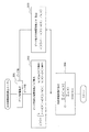
[形状相関係数算出ルーチン]
図3の形状相関係数算出ルーチンは、上記図2のノック判定閾値補正ルーチンのステップ103で実行されるサブルーチンである。本ルーチンが起動されると、まずステップ201で、検出したセンサ出力の波形(以下「検出波形」という)のピーク位置を検出する(図5参照)。
[Shape correlation coefficient calculation routine]
The shape correlation coefficient calculation routine of FIG. 3 is a subroutine executed in
そして、次のステップ202で、ピーク前の検出波形s[θ]を理想ノック波形a[θ]と比較して、ピーク前の形状相関係数c[θ]を次のようにして算出する。ピーク前のクランク角θにおける検出波形s[θ]が理想ノック波形a[θ]以下であるか否かを判定して、ピーク前のクランク角θにおける検出波形s[θ]が理想ノック波形a[θ]以下であれば、ピーク前のクランク角θにおけるピーク前形状相関係数c[θ]を“1”にセットし、ピーク前のクランク角θにおける検出波形s[θ]が理想ノック波形a[θ]よりも大きければ、ピーク前のクランク角θにおけるピーク前形状相関係数c[θ]を次式により算出する。
c[θ]=1−{s[θ]−a[θ]}/a[θ]
Then, in the
c [θ] = 1− {s [θ] −a [θ]} / a [θ]
この場合、検出波形s[θ]と理想ノック波形a[θ]との偏差{s[θ]−a[θ]}が大きくなるほど、相関性が低くなるため、ピーク前形状相関係数c[θ]が減少する。図6にピーク前形状相関係数c[θ]の算出例が示されている。 In this case, as the deviation {s [θ] −a [θ]} between the detected waveform s [θ] and the ideal knock waveform a [θ] increases, the correlation decreases, and thus the pre-peak shape correlation coefficient c [ θ] decreases. FIG. 6 shows an example of calculating the pre-peak shape correlation coefficient c [θ].
また、ステップ203で、ピーク後の検出波形s[θ]と理想ノック波形a[θ]とを用いて、ピーク後のクランク角θにおけるピーク後形状相関係数c[θ]を次式により算出する。
c[θ]=1−|s[θ]−a[θ]|/a[θ]
In
c [θ] = 1− | s [θ] −a [θ] | / a [θ]
この場合も、検出波形s[θ]と理想ノック波形a[θ]との偏差の絶対値|s[θ]−a[θ]|が大きくなるほど、相関性が低くなるため、ピーク前形状相関係数c[θ]が減少する。図7にピーク後形状相関係数c[θ]の算出例が示されている。 Also in this case, since the correlation decreases as the absolute value | s [θ] −a [θ] | of the deviation between the detected waveform s [θ] and the ideal knock waveform a [θ] increases, the pre-peak shape phase The relation number c [θ] decreases. FIG. 7 shows a calculation example of the post-peak shape correlation coefficient c [θ].
以上のようにしてピーク前後の所定期間の全てのクランク角θについて形状相関係数c[θ]を算出する処理を繰り返した後、ステップ204に進み、最終的な形状相関係数Cを次式により算出する。
C=Σc[θ]・a[θ]/Σa[θ]
これにより、形状相関係数Cは常に1以下(0≦C≦1)になり、検出波形s[θ]と理想ノック波形a[θ]との相関性が高いほど、形状相関係数Cは1に近い値になる。
After repeating the process of calculating the shape correlation coefficient c [θ] for all crank angles θ in a predetermined period before and after the peak as described above, the process proceeds to step 204, and the final shape correlation coefficient C is expressed by the following equation. Calculated by
C = Σc [θ] · a [θ] / Σa [θ]
Thereby, the shape correlation coefficient C is always 1 or less (0 ≦ C ≦ 1), and the higher the correlation between the detected waveform s [θ] and the ideal knock waveform a [θ], the more the shape correlation coefficient C is A value close to 1.
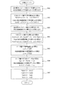
[正規化ルーチン]
図4の正規化ルーチンは、前記図2のノック判定閾値補正ルーチンのステップ104で実行されるサブルーチンであり、特許請求の範囲でいう統計処理手段と正規化手段としての役割を果たす。本ルーチンが起動されると、まずステップ301で、ECU27のRAMに記憶されている前回算出したピーク値Pの平均値Pav(i-1)と形状相関係数Cの平均値Cav(i-1)を読み込む。
[Normalization routine]
The normalization routine of FIG. 4 is a subroutine executed in
この後、ステップ302に進み、今回のピーク値Pの平均値Pav(i)を次のなまし処理の式を用いて算出する。
Pav(i)=α1 ・P+(1−α1)・Pav(i-1)
上式において、α1 はなまし係数である。
Thereafter, the process proceeds to step 302, where the average value Pav (i) of the current peak value P is calculated using the following equation for the annealing process.
Pav (i) = α1 · P + (1−α1) · Pav (i-1)
In the above equation, α1 is an annealing coefficient.
同様に、今回の形状相関係数Cの平均値Cav(i)を次のなまし処理の式を用いて算出する。
Cav(i)=α2 ・C+(1−α2)・Cav(i-1)
上式において、α2 はなまし係数である。この場合、なまし係数α1 ,α2 は演算処理の簡略化のために、固定値としても良いが、エンジン運転状態に応じてなまし係数α1 ,α2 をマップ又は数式等により変化させるようにしても良い。このようにすれば、例えば定常運転時には、平均値Pav(i)、Cav(i) の正確性を重視した設定にし、過渡運転時には、追従性を重視した設定にするといった具合に、エンジン運転状態に応じて、正確性や追従性を調整できる利点がある。
Similarly, the average value Cav (i) of the current shape correlation coefficient C is calculated using the following equation for the annealing process.
Cav (i) = α2 C + (1-α2) Cav (i-1)
In the above equation, α2 is an annealing coefficient. In this case, the smoothing coefficients α1 and α2 may be fixed values for simplification of the arithmetic processing, but the smoothing coefficients α1 and α2 may be changed by a map or a mathematical expression according to the engine operating state. good. In this way, for example, in the steady operation, the setting is made with an emphasis on the accuracy of the average values Pav (i) and Cav (i), and in the transient operation, the setting is made with an emphasis on the followability. There is an advantage that accuracy and followability can be adjusted according to the above.
この後、ステップ303に進み、ECU27のRAMに記憶されている前回算出したピーク値Pの分散Vp(i-1)と形状相関係数Cの分散Vc(i-1)を読み込む。この後、ステップ304に進み、今回のピーク値Pの分散Vp(i)を次のなまし処理の式を用いて算出する。
Vp(i)=β1 ・{P−Pav(i)]2 +(1−β1)・Vp(i-1)
上式において、β1 はなまし係数である。
Thereafter, the process proceeds to step 303, and the previously calculated variance Vp (i-1) of the peak value P and variance Vc (i-1) of the shape correlation coefficient C stored in the RAM of the
Vp (i) = β1 · {P−Pav (i)] 2 + (1−β1) · Vp (i-1)
In the above equation, β1 is an annealing coefficient.
同様に、今回の形状相関係数Cの分散Vc(i)を次のなまし処理の式を用いて算出する。
Vc(i)=β2 ・{C−Cav(i)]2 +(1−β2)・Vc(i-1)
上式において、β2 はなまし係数である。この場合も、なまし係数β1 ,β2 は演算処理の簡略化のために、固定値としても良いが、エンジン運転状態に応じてなまし係数β1 ,β2 をマップ又は数式等により変化させるようにしても良い。このようにすれば、例えば定常運転時には、分散Vp 、Vc の正確性を重視した設定にし、過渡運転時には、追従性を重視した設定にするといった具合に、エンジン運転状態に応じて、正確性や追従性を調整できる利点がある。
Similarly, the variance Vc (i) of the current shape correlation coefficient C is calculated using the following equation for the annealing process.
Vc (i) = β2 · {C−Cav (i)] 2 + (1−β2) · Vc (i-1)
In the above equation, β2 is an annealing coefficient. In this case as well, the smoothing coefficients β1 and β2 may be fixed values for simplification of the arithmetic processing, but the smoothing coefficients β1 and β2 are changed by a map or a mathematical formula according to the engine operating state. Also good. In this way, for example, in steady operation, the setting is made with an emphasis on the accuracy of the variances Vp and Vc, and in transient operation, the setting is made with an emphasis on follow-up. There is an advantage that followability can be adjusted.
この後、ステップ305に進み、ピーク値Pの分散Vp(i)の平方根を演算してピーク値Pの標準偏差σp を求めると共に、形状相関係数Cの分散Vc(i)の平方根を演算して形状相関係数Cの標準偏差σc を求める。
σp =√Vp(i)
σc =√Vc(i)
Thereafter, the process proceeds to step 305, where the square root of the variance Vp (i) of the peak value P is calculated to obtain the standard deviation σp of the peak value P, and the square root of the variance Vc (i) of the shape correlation coefficient C is calculated. Thus, the standard deviation σc of the shape correlation coefficient C is obtained.
σp = √Vp (i)
σc = √Vc (i)
この後、ステップ306に進み、ピーク値Pの正規化データSp と形状相関係数Cの正規化データSc をそれぞれ次式により算出する。
Sp ={P−Pav(i)]/σp
Sc ={C−Cav(i)]/σc
Thereafter, the process proceeds to step 306, where the normalized data Sp of the peak value P and the normalized data Sc of the shape correlation coefficient C are calculated by the following equations.
Sp = {P-Pav (i)] / σp
Sc = {C-Cav (i)] / σc
この後、ステップ307に進み、次回の正規化演算に備えるために、今回の平均値Pav(i) ,Cav(i) と分散Vp(i),Vc(i)をそれぞれ前回値Pav(i-1) ,Cav(i-1) ,Vp(i-1),Vc(i-1)としてRAMに記憶し、本ルーチンを終了する。 Thereafter, the process proceeds to step 307, and in order to prepare for the next normalization calculation, the current average values Pav (i) and Cav (i) and the variances Vp (i) and Vc (i) are respectively used as the previous values Pav (i− 1), Cav (i-1), Vp (i-1), Vc (i-1) are stored in the RAM, and this routine is terminated.
以上説明した本実施例によれば、点火毎にノックセンサ28の出力からノックの特徴を表す2つのデータ(ピーク値と形状相関係数)を抽出し、これら2つのデータをそれぞれなまし処理して各データの平均値を近似的に求めると共に、なまし処理前後のデータの偏差を二乗した値をなまし処理して近似的に分散Vを求め、この分散Vの平方根を演算して近似的に標準偏差σを求めるようにしたので、データのサンプリング毎に平均値と標準偏差σを逐次更新できて、多数のデータをECU27のRAMに記憶し続ける必要がなくなり、少ないRAM容量で、平均値と標準偏差σを近似的に演算することができる。しかも、上位累積数%点を用いないため、分布の上位ばらつきの影響を受けずに、平均値と標準偏差σを演算することができて、平均値と標準偏差σの近似精度を向上させることができる。更に、なまし処理を用いることで、過渡状態での追従性も向上させることができる。
According to the present embodiment described above, two data (a peak value and a shape correlation coefficient) representing knock characteristics are extracted from the output of the
更に、本実施例では、データを平均値と標準偏差σを用いて正規化(標準化、無次元化)するようにしたので、運転条件が変化しても、その前後にサンプリングしたデータを、いずれも標準的な運転条件下でのデータに補正することができる。これにより、運転条件毎に区分してデータを統計処理する必要がなくなり、統計処理の負荷を軽減できると共に、運転条件の変化による統計処理精度の低下を回避することができる。 Furthermore, in this embodiment, since the data is normalized (standardized, dimensionless) using the average value and the standard deviation σ, the data sampled before and after the operation condition is changed. Can also be corrected to data under standard operating conditions. As a result, it is not necessary to perform statistical processing of data separately for each operating condition, the load of statistical processing can be reduced, and a decrease in statistical processing accuracy due to changes in operating conditions can be avoided.
また、本実施例では、ノックセンサ28の出力からセンサ出力からノックの特徴を表す2つのデータ(ピーク値と形状相関係数)を求めてこれら2つのデータを正規化して所定点火回数分の分布を求めるようにしているため、前記特許文献1のようにセンサ出力のピーク値のみの分布とは異なり、ノイズとノックとを区別できる分布を作成することができ、ノイズによるノック判定精度の悪化の問題を解決できて、ノック判定の精度・信頼性を向上させることができる。
Further, in this embodiment, two data (peak value and shape correlation coefficient) representing knock characteristics are obtained from the sensor output from the output of the
更に、本実施例では、検出分布と理想ノック分布との相関性(類似性)を表すノック判定用の相関係数をノックレベルの指標として算出し、このノック判定用の相関係数(ノックレベル)に基づいて1燃焼毎のノック判定に用いるノック判定閾値を補正するようにしたので、センサ出力に機械的・電気的なノイズが重畳した場合でも、ノック判定閾値を精度良く補正することができ、ノイズによるノック判定精度の低下を防止できる。しかも、製造ばらつきや経年変化による振動レベルの変化に追従してノック判定閾値を自動的に補正することができるため、常に適正なノック判定閾値を使用して精度の良いノック判定を行うことができると共に、設計・開発技術者がノック判定閾値を適合する際に、製造ばらつきや経年変化の影響を詳細に検討する必要がなくなり、ノック判定閾値の適合作業を簡略化できるという利点もある。 Furthermore, in this embodiment, a knock determination correlation coefficient representing the correlation (similarity) between the detected distribution and the ideal knock distribution is calculated as a knock level index, and this knock determination correlation coefficient (knock level) is calculated. ), The knock determination threshold used for the knock determination for each combustion is corrected. Therefore, even when mechanical and electrical noise is superimposed on the sensor output, the knock determination threshold can be accurately corrected. In addition, it is possible to prevent a decrease in knock determination accuracy due to noise. In addition, since the knock determination threshold value can be automatically corrected following changes in the vibration level due to manufacturing variations and aging, accurate knock determination can always be performed using an appropriate knock determination threshold value. In addition, when the design / development engineer adapts the knock determination threshold value, it is not necessary to examine in detail the effects of manufacturing variations and secular changes, and there is an advantage that the operation for adjusting the knock determination threshold value can be simplified.
尚、本実施例では、ノック状態に応じた波形の信号を出力するセンサとして、シリンダブロックの振動を検出するノックセンサ28を用いるようにしたが、燃焼圧を検出する燃焼圧センサを用いるようにしても良い。
In this embodiment, the
また、本発明の適用範囲は、ノック判定に限定されず、エンジン運転状態を検出するセンサの出力を周期的にサンプリングして統計的に処理するシステムにおいて、平均値や標準偏差σ等を算出する必要がある様々な制御に本発明を適用して実施できる。 Further, the scope of application of the present invention is not limited to knock determination, and an average value, standard deviation σ, and the like are calculated in a system that periodically samples and statistically processes the output of a sensor that detects an engine operating state. The present invention can be applied to various necessary controls.
11…エンジン(内燃機関)、12…吸気管、15…スロットルバルブ、18…吸気管圧力センサ、20…燃料噴射弁、22…排気管、23…触媒、24…空燃比センサ、27…ECU(統計処理手段,正規化手段)、28…ノックセンサ
DESCRIPTION OF
Claims (5)
前記統計処理手段は、前記センサ出力のサンプリング毎にサンプリングしたデータをなまし処理して近似的に該データの平均値を求める手段と、前記なまし処理前後のデータの偏差を二乗した値を用いて該データの散らばりの度合いを表す指標を演算する手段とを有することを特徴とする内燃機関の制御装置。 Control of an internal combustion engine comprising statistical processing means for periodically sampling and statistically processing the output of a sensor for detecting the operating state of the internal combustion engine, and controlling the operation of the internal combustion engine using the processing result of the statistical processing means In the device
The statistical processing means uses means for smoothing the sampled data for each sampling of the sensor output to obtain an average value of the data approximately, and a value obtained by squaring the deviation of the data before and after the smoothing process. And a means for calculating an index representing the degree of dispersion of the data.
前記統計処理手段は、前記なまし処理前後のデータの偏差を二乗した値をなまし処理して近似的に分散Vを求め、この分散Vの平方根を演算して近似的に標準偏差σを求めることを特徴とする請求項1に記載の内燃機関の制御装置。 The index representing the degree of dispersion of the data is the standard deviation σ,
The statistical processing means smoothes a value obtained by squaring the deviation of the data before and after the annealing process to approximately obtain a variance V, and calculates a square root of the variance V to approximately obtain a standard deviation σ. The control apparatus for an internal combustion engine according to claim 1.
前記統計処理手段は、前記センサ出力のサンプリング毎に該センサ出力のノック周波数成分のピーク値と、該センサ出力の波形とノック特有の波形を表す理想ノック波形との相関性を表す形状相関係数とを前記データとして求めて、これらピーク値と形状相関係数をそれぞれ前記正規化手段により正規化し、正規化したピーク値と形状相関係数に関する所定点火回数分の分布を求め、この分布の形状がノック発生時に現れる特徴を有するか否かでノックの発生状態を判定することを特徴とする請求項3に記載の内燃機関の制御装置。 The sensor is a sensor that outputs a signal having a waveform corresponding to a knock state of the internal combustion engine,
The statistical processing means includes a shape correlation coefficient representing a correlation between a peak value of a knock frequency component of the sensor output and an ideal knock waveform representing a knock-specific waveform for each sampling of the sensor output. As the data, the peak value and the shape correlation coefficient are normalized by the normalizing means, respectively, and a distribution for a predetermined number of ignition times related to the normalized peak value and the shape correlation coefficient is obtained. 4. The control device for an internal combustion engine according to claim 3, wherein the state of occurrence of knocking is determined based on whether or not has a characteristic that appears when knocking occurs.
Priority Applications (4)
| Application Number | Priority Date | Filing Date | Title |
|---|---|---|---|
| JP2004119850A JP4375728B2 (en) | 2004-04-15 | 2004-04-15 | Control device for internal combustion engine |
| US11/106,568 US7054735B2 (en) | 2004-04-15 | 2005-04-15 | Apparatus and method for controlling internal combustion engine |
| CN2005100646077A CN1683781B (en) | 2004-04-15 | 2005-04-15 | Control device and control method for internal combustion engine |
| EP05008324A EP1586881B1 (en) | 2004-04-15 | 2005-04-15 | Apparatus and method for controlling internal combustion engine |
Applications Claiming Priority (1)
| Application Number | Priority Date | Filing Date | Title |
|---|---|---|---|
| JP2004119850A JP4375728B2 (en) | 2004-04-15 | 2004-04-15 | Control device for internal combustion engine |
Publications (2)
| Publication Number | Publication Date |
|---|---|
| JP2005299580A true JP2005299580A (en) | 2005-10-27 |
| JP4375728B2 JP4375728B2 (en) | 2009-12-02 |
Family
ID=34935255
Family Applications (1)
| Application Number | Title | Priority Date | Filing Date |
|---|---|---|---|
| JP2004119850A Expired - Fee Related JP4375728B2 (en) | 2004-04-15 | 2004-04-15 | Control device for internal combustion engine |
Country Status (4)
| Country | Link |
|---|---|
| US (1) | US7054735B2 (en) |
| EP (1) | EP1586881B1 (en) |
| JP (1) | JP4375728B2 (en) |
| CN (1) | CN1683781B (en) |
Cited By (6)
| Publication number | Priority date | Publication date | Assignee | Title |
|---|---|---|---|---|
| JP2007211722A (en) * | 2006-02-10 | 2007-08-23 | Toyota Motor Corp | Control device for internal combustion engine |
| JP2009019547A (en) * | 2007-07-11 | 2009-01-29 | Toyota Motor Corp | Internal combustion engine knock determination device |
| DE102011083875A1 (en) | 2010-10-04 | 2012-04-05 | Mazda Motor Corporation | Knock control device for an internal combustion engine |
| JP2013189919A (en) * | 2012-03-14 | 2013-09-26 | Mitsubishi Electric Corp | Internal combustion engine knock controlling apparatus |
| CN109470389A (en) * | 2018-11-27 | 2019-03-15 | 上海应用技术大学 | Strain-type torque measurement system and method |
| JP2019145111A (en) * | 2013-04-10 | 2019-08-29 | ロベルト・ボッシュ・ゲゼルシャフト・ミト・ベシュレンクテル・ハフツングRobert Bosch Gmbh | Model calculation unit for calculating function model based on data, controller, and method |
Families Citing this family (23)
| Publication number | Priority date | Publication date | Assignee | Title |
|---|---|---|---|---|
| JP4410674B2 (en) | 2004-04-22 | 2010-02-03 | トヨタ自動車株式会社 | Internal combustion engine knock determination device and ignition control system including the same |
| JP4605642B2 (en) * | 2004-12-14 | 2011-01-05 | 株式会社デンソー | Internal combustion engine knock determination device |
| JP4538383B2 (en) * | 2005-06-28 | 2010-09-08 | トヨタ自動車株式会社 | Ignition timing control device for internal combustion engine |
| JP4390774B2 (en) * | 2006-01-27 | 2009-12-24 | トヨタ自動車株式会社 | Ignition timing control device for internal combustion engine |
| JP4229142B2 (en) * | 2006-06-21 | 2009-02-25 | トヨタ自動車株式会社 | Knock control device for internal combustion engine |
| US8527187B2 (en) * | 2007-03-13 | 2013-09-03 | GM Global Technology Operations LLC | Systems and methods for digital signal processing |
| US7918130B2 (en) * | 2007-05-11 | 2011-04-05 | GM Global Technology Operations LLC | Methods and systems to identify cam phaser hardware degradation |
| US7899652B2 (en) * | 2007-08-31 | 2011-03-01 | Toyota Motor Engineering & Manufacturing North America, Inc. | Linear programming support vector regression with wavelet kernel |
| CN101235783B (en) * | 2007-12-20 | 2010-10-13 | 华夏龙晖(北京)汽车电子科技有限公司 | Knock controlling device and method |
| US8676514B2 (en) * | 2010-06-29 | 2014-03-18 | General Electric Company | System and method for monitoring health of airfoils |
| CN102155322A (en) * | 2011-03-10 | 2011-08-17 | 重庆长安汽车股份有限公司 | Method for judging knock of engine |
| JP2013068160A (en) * | 2011-09-22 | 2013-04-18 | Suzuki Motor Corp | Knocking control device of engine |
| US8738271B2 (en) | 2011-12-16 | 2014-05-27 | Toyota Motor Engineering & Manufacturing North America, Inc. | Asymmetric wavelet kernel in support vector learning |
| JP5892786B2 (en) * | 2011-12-26 | 2016-03-23 | 三菱電機株式会社 | Knock control device for internal combustion engine |
| JP5843652B2 (en) * | 2012-02-20 | 2016-01-13 | 三菱電機株式会社 | Knock control device for internal combustion engine |
| US9279406B2 (en) | 2012-06-22 | 2016-03-08 | Illinois Tool Works, Inc. | System and method for analyzing carbon build up in an engine |
| BR112015030516B1 (en) * | 2013-06-05 | 2021-08-31 | Toyota Jidosha Kabushiki Kaisha | CONTROL DEVICE TO CONTROL A COMBUSTION STATE OF AN INTERNAL COMBUSTION ENGINE |
| JP2015083792A (en) * | 2013-10-25 | 2015-04-30 | ヤマハ発動機株式会社 | Power unit and vehicle |
| FR3074542B1 (en) * | 2017-12-06 | 2019-12-20 | IFP Energies Nouvelles | METHOD FOR CONTROLLING AN INTERNAL COMBUSTION ENGINE WITH CONTROLLED IGNITION USING A CLICK ESTIMATOR |
| CN110750520A (en) * | 2019-10-23 | 2020-02-04 | 深圳前海微众银行股份有限公司 | Feature data processing method, apparatus, device and readable storage medium |
| US11255241B1 (en) * | 2020-10-13 | 2022-02-22 | GM Global Technology Operations LLC | Systems and methods for selective catalytic reduction (SCR) failure detection |
| US11982246B2 (en) * | 2020-11-23 | 2024-05-14 | Transportation Ip Holdings, Llc | Methods and systems for engine |
| CN113153553B (en) * | 2021-03-23 | 2022-08-26 | 长沙理工大学 | Optimization method for linear characteristic of oil injection quantity of electric control oil injector |
Family Cites Families (9)
| Publication number | Priority date | Publication date | Assignee | Title |
|---|---|---|---|---|
| JPS6060621A (en) | 1983-09-14 | 1985-04-08 | Toyo Denso Co Ltd | Optical switch device |
| DE69017063T2 (en) * | 1989-04-14 | 1995-09-21 | Hitachi Ltd | Engine monitor, equipped with knock detector. |
| US5608633A (en) * | 1991-07-29 | 1997-03-04 | Nissan Motor Co., Ltd. | System and method for detecting knocking for internal combustion engine |
| JP2976709B2 (en) | 1992-08-04 | 1999-11-10 | 松下電器産業株式会社 | Video tape recorder |
| US5386722A (en) * | 1993-03-24 | 1995-02-07 | Ford Motor Company | Method and apparatus for statistically determining knock borderline and evaluating knock intensity in an internal combustion engine |
| JP2893233B2 (en) * | 1993-12-09 | 1999-05-17 | 株式会社ユニシアジェックス | Diagnostic device for in-cylinder pressure sensor |
| JP2864975B2 (en) * | 1993-12-22 | 1999-03-08 | 三菱自動車工業株式会社 | Control device for internal combustion engine |
| IT1281052B1 (en) * | 1995-12-01 | 1998-02-11 | Fiat Ricerche | DETONATION DETECTION METHOD FOR INTERNAL COMBUSTION ENGINES. |
| IT1294853B1 (en) * | 1997-09-09 | 1999-04-23 | Fiat Ricerche | METHOD OF DETONATION DETECTION AND CONTROL FOR AN INTERNAL COMBUSTION ENGINE. |
-
2004
- 2004-04-15 JP JP2004119850A patent/JP4375728B2/en not_active Expired - Fee Related
-
2005
- 2005-04-15 EP EP05008324A patent/EP1586881B1/en not_active Expired - Lifetime
- 2005-04-15 US US11/106,568 patent/US7054735B2/en not_active Expired - Fee Related
- 2005-04-15 CN CN2005100646077A patent/CN1683781B/en not_active Expired - Fee Related
Cited By (8)
| Publication number | Priority date | Publication date | Assignee | Title |
|---|---|---|---|---|
| JP2007211722A (en) * | 2006-02-10 | 2007-08-23 | Toyota Motor Corp | Control device for internal combustion engine |
| JP2009019547A (en) * | 2007-07-11 | 2009-01-29 | Toyota Motor Corp | Internal combustion engine knock determination device |
| DE102011083875A1 (en) | 2010-10-04 | 2012-04-05 | Mazda Motor Corporation | Knock control device for an internal combustion engine |
| US8949006B2 (en) | 2010-10-04 | 2015-02-03 | Mitsubishi Electric Corporation | Knock control apparatus for internal combustion engine |
| DE102011083875B4 (en) * | 2010-10-04 | 2019-08-29 | Mazda Motor Corporation | Knock control device for an internal combustion engine |
| JP2013189919A (en) * | 2012-03-14 | 2013-09-26 | Mitsubishi Electric Corp | Internal combustion engine knock controlling apparatus |
| JP2019145111A (en) * | 2013-04-10 | 2019-08-29 | ロベルト・ボッシュ・ゲゼルシャフト・ミト・ベシュレンクテル・ハフツングRobert Bosch Gmbh | Model calculation unit for calculating function model based on data, controller, and method |
| CN109470389A (en) * | 2018-11-27 | 2019-03-15 | 上海应用技术大学 | Strain-type torque measurement system and method |
Also Published As
| Publication number | Publication date |
|---|---|
| CN1683781A (en) | 2005-10-19 |
| JP4375728B2 (en) | 2009-12-02 |
| US7054735B2 (en) | 2006-05-30 |
| EP1586881A2 (en) | 2005-10-19 |
| EP1586881B1 (en) | 2012-10-03 |
| EP1586881A3 (en) | 2006-09-27 |
| US20050234632A1 (en) | 2005-10-20 |
| CN1683781B (en) | 2010-06-16 |
Similar Documents
| Publication | Publication Date | Title |
|---|---|---|
| JP4375728B2 (en) | Control device for internal combustion engine | |
| JP4390104B2 (en) | Internal combustion engine knock determination device | |
| EP1924831B1 (en) | Knock determination apparatus and method for engines | |
| US6688286B2 (en) | Knock control apparatus for engine | |
| CN101375051B (en) | Method and device for control ignition timing through knock control in an internal combustion engine | |
| JP4550917B2 (en) | Control device for internal combustion engine | |
| US20080306677A1 (en) | Knocking state determination device | |
| JP5968504B1 (en) | Control device for an internal combustion engine with a supercharger | |
| US8005607B2 (en) | Device and method for controlling ignition timing of internal combustion engine | |
| JP4925251B2 (en) | Internal combustion engine knock determination device | |
| CN114689324B (en) | Method for calibrating ignition advance angle, bench test equipment and engine control system | |
| JPH0579441A (en) | Ignition timing control device for internal combustion engine | |
| EP3961020B1 (en) | Engine system control method, and engine system | |
| JPH04326036A (en) | Knocking detection method | |
| JP2004340104A (en) | Method for correcting output signal of vibration detection sensor, and correction coefficient calculation device for output signal of vibration detection sensor | |
| JPH05202798A (en) | Knock control device for internal combustion engine |
Legal Events
| Date | Code | Title | Description |
|---|---|---|---|
| A621 | Written request for application examination |
Free format text: JAPANESE INTERMEDIATE CODE: A621 Effective date: 20070117 |
|
| A521 | Request for written amendment filed |
Free format text: JAPANESE INTERMEDIATE CODE: A523 Effective date: 20080416 |
|
| A711 | Notification of change in applicant |
Free format text: JAPANESE INTERMEDIATE CODE: A711 Effective date: 20080416 |
|
| RD02 | Notification of acceptance of power of attorney |
Free format text: JAPANESE INTERMEDIATE CODE: A7422 Effective date: 20080426 |
|
| A521 | Request for written amendment filed |
Free format text: JAPANESE INTERMEDIATE CODE: A821 Effective date: 20080416 |
|
| A521 | Request for written amendment filed |
Free format text: JAPANESE INTERMEDIATE CODE: A523 Effective date: 20080530 |
|
| A131 | Notification of reasons for refusal |
Free format text: JAPANESE INTERMEDIATE CODE: A131 Effective date: 20090106 |
|
| A977 | Report on retrieval |
Free format text: JAPANESE INTERMEDIATE CODE: A971007 Effective date: 20090108 |
|
| A521 | Request for written amendment filed |
Free format text: JAPANESE INTERMEDIATE CODE: A523 Effective date: 20090305 |
|
| A131 | Notification of reasons for refusal |
Free format text: JAPANESE INTERMEDIATE CODE: A131 Effective date: 20090508 |
|
| A521 | Request for written amendment filed |
Free format text: JAPANESE INTERMEDIATE CODE: A523 Effective date: 20090702 |
|
| TRDD | Decision of grant or rejection written | ||
| A01 | Written decision to grant a patent or to grant a registration (utility model) |
Free format text: JAPANESE INTERMEDIATE CODE: A01 Effective date: 20090904 |
|
| A01 | Written decision to grant a patent or to grant a registration (utility model) |
Free format text: JAPANESE INTERMEDIATE CODE: A01 |
|
| A61 | First payment of annual fees (during grant procedure) |
Free format text: JAPANESE INTERMEDIATE CODE: A61 Effective date: 20090904 |
|
| R150 | Certificate of patent or registration of utility model |
Ref document number: 4375728 Country of ref document: JP Free format text: JAPANESE INTERMEDIATE CODE: R150 |
|
| FPAY | Renewal fee payment (event date is renewal date of database) |
Free format text: PAYMENT UNTIL: 20120918 Year of fee payment: 3 |
|
| FPAY | Renewal fee payment (event date is renewal date of database) |
Free format text: PAYMENT UNTIL: 20120918 Year of fee payment: 3 |
|
| FPAY | Renewal fee payment (event date is renewal date of database) |
Free format text: PAYMENT UNTIL: 20130918 Year of fee payment: 4 |
|
| R250 | Receipt of annual fees |
Free format text: JAPANESE INTERMEDIATE CODE: R250 |
|
| LAPS | Cancellation because of no payment of annual fees |