JP2005299562A - Exhaust gas purification device for internal combustion engine - Google Patents
Exhaust gas purification device for internal combustion engine Download PDFInfo
- Publication number
- JP2005299562A JP2005299562A JP2004119136A JP2004119136A JP2005299562A JP 2005299562 A JP2005299562 A JP 2005299562A JP 2004119136 A JP2004119136 A JP 2004119136A JP 2004119136 A JP2004119136 A JP 2004119136A JP 2005299562 A JP2005299562 A JP 2005299562A
- Authority
- JP
- Japan
- Prior art keywords
- temperature
- catalyst
- exhaust
- exhaust gas
- temperature increase
- Prior art date
- Legal status (The legal status is an assumption and is not a legal conclusion. Google has not performed a legal analysis and makes no representation as to the accuracy of the status listed.)
- Pending
Links
Images


Landscapes
- Exhaust Gas After Treatment (AREA)
- Processes For Solid Components From Exhaust (AREA)
- Combined Controls Of Internal Combustion Engines (AREA)
- Exhaust Gas Treatment By Means Of Catalyst (AREA)
Abstract
【課題】触媒が活性状態にないにも関わらず同触媒に未燃燃料が供給されることを好適に抑止することのできる内燃機関の排気浄化装置を提供する。
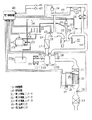
【解決手段】排気浄化装置は、排気通路14に第1の触媒コンバータ31、第2の触媒コンバータ32、及び第3の触媒コンバータ33を備えている。そして、この第1の触媒コンバータ31の排気下流側で且つ第2の触媒コンバータ32の排気上流側には第1温度センサ35が配設されるとともに、第2の触媒コンバータ32の排気下流側には第2温度センサ36が配設されている。電子制御装置40は、この両温度センサ35,36により計測される排気温度のうちの低い方の排気温度が触媒の活性温度範囲の下限に対応して設定された下限設定温度を超えるときに触媒が活性状態にあると判断する。
【選択図】 図1An exhaust emission control device for an internal combustion engine is provided that can suitably prevent unburned fuel from being supplied to the catalyst even though the catalyst is not in an active state.
An exhaust purification device includes a first catalytic converter, a second catalytic converter, and a third catalytic converter in an exhaust passage. A first temperature sensor 35 is disposed on the exhaust downstream side of the first catalytic converter 31 and on the exhaust upstream side of the second catalytic converter 32, and on the exhaust downstream side of the second catalytic converter 32. Is provided with a second temperature sensor 36. The electronic control unit 40 detects the catalyst when the lower exhaust temperature of the exhaust temperatures measured by the temperature sensors 35 and 36 exceeds a lower limit set temperature set corresponding to the lower limit of the catalyst active temperature range. Is determined to be active.
[Selection] Figure 1
Description
本発明は、内燃機関の排気系に設けられる触媒を通じて排気を浄化する排気浄化装置に関する。 The present invention relates to an exhaust purification device that purifies exhaust through a catalyst provided in an exhaust system of an internal combustion engine.
この種の排気浄化装置は、内燃機関、例えば希薄燃焼を行う内燃機関から排出される排気中の窒素酸化物(NOx)を浄化すべく、吸蔵還元型のNOx触媒が担持された触媒を排気通路に備えている。このNOx触媒は、周囲の雰囲気が高酸素濃度状態である場合には排気中の窒素酸化物NOxを吸蔵し、周囲の雰囲気が低酸素濃度状態であり、かつ還元剤となる未燃燃料(炭化水素(HC))が存在している場合には、吸蔵した窒素酸化物を還元することにより排気を浄化する。 This type of exhaust gas purification apparatus is configured to remove a catalyst on which an NOx storage reduction catalyst is supported in an exhaust passage in order to purify nitrogen oxide (NOx) in exhaust gas discharged from an internal combustion engine, for example, an internal combustion engine that performs lean combustion. In preparation. This NOx catalyst occludes nitrogen oxides NOx in the exhaust when the ambient atmosphere is in a high oxygen concentration state, and the unburnt fuel (carbonized carbon) that is a low oxygen concentration state in the exhaust and serves as a reducing agent. When hydrogen (HC) is present, exhaust gas is purified by reducing the stored nitrogen oxides.
ところで、内燃機関の燃料等には硫黄成分が含まれているため、燃焼に際してはその酸化物である硫黄酸化物(SOx)が生成され、上記窒素酸化物と同様にNOx触媒に吸蔵される。この硫黄酸化物は化学的に安定な物質であるため、排気の空燃比を理論空燃比よりもリッチ側にしてもNOx触媒から放出されにくい。このため、硫黄酸化物の吸蔵量が増加した状態(S被毒)になると、その吸蔵量分だけ窒素酸化物の吸蔵量が減少し、NOx浄化能力が低下してしまう。 By the way, since the fuel and the like of the internal combustion engine contain a sulfur component, sulfur oxide (SOx), which is an oxide thereof, is generated during combustion and is stored in the NOx catalyst in the same manner as the nitrogen oxide. Since this sulfur oxide is a chemically stable substance, it is not easily released from the NOx catalyst even if the air-fuel ratio of the exhaust is richer than the stoichiometric air-fuel ratio. For this reason, when the storage amount of sulfur oxide is increased (S poisoning), the storage amount of nitrogen oxide is decreased by the storage amount, and the NOx purification capacity is lowered.
そこで、従来からNOx触媒の浄化能力を維持すべく、NOx触媒に吸蔵された硫黄酸化物を放出させるS被毒回復処理が行われている。そして、このS被毒回復処理を行うにあたっては、排気通路に配設された燃料添加弁から未燃燃料を添加する等して排気に未燃燃料を供給し、その未燃燃料が酸化反応する際の発熱を利用して吸蔵されている硫黄酸化物を放出可能な温度(例えば600〜700℃程度)まで触媒床温を上昇させるといった、いわゆる昇温制御が実施される。そして、この昇温制御により十分に触媒床温が高温化されると、その未燃燃料中の炭化水素等が還元剤として働き、硫黄酸化物が還元されてNOx触媒から放出される。なお、昇温制御は、こうしたS被毒回復処理の他、触媒やフィルタ等に付着した粒子状物質(PM)を高温で焼失させるPM再生処理等の際にも行われる。 Therefore, in order to maintain the purification capacity of the NOx catalyst, an S poisoning recovery process for releasing sulfur oxide stored in the NOx catalyst has been performed. In performing the S poisoning recovery process, unburned fuel is supplied to the exhaust gas by adding unburned fuel from a fuel addition valve disposed in the exhaust passage, and the unburned fuel undergoes an oxidation reaction. So-called temperature rise control is performed such that the catalyst bed temperature is raised to a temperature at which the stored sulfur oxides can be released (for example, about 600 to 700 ° C.) using the generated heat. When the catalyst bed temperature is sufficiently increased by this temperature increase control, hydrocarbons in the unburned fuel function as a reducing agent, and the sulfur oxide is reduced and released from the NOx catalyst. In addition to the S poisoning recovery process, the temperature increase control is also performed during a PM regeneration process in which particulate matter (PM) adhering to a catalyst, a filter, or the like is burned off at a high temperature.
ところで、上記昇温制御を行うにあたっては、燃料添加弁から排気に供給する未燃燃料が触媒において酸化反応し得るだけの触媒床温、すなわち触媒が活性状態にあるときでないと供給された未燃燃料が酸化反応せず、排気性状を悪化させてしまうこととなる。したがって、このような事態を回避すべく上記触媒コンバータの触媒床温を把握したうえで上述したような昇温制御を実施する必要がある。 By the way, in performing the above temperature rise control, the unburned fuel supplied to the exhaust gas from the fuel addition valve is at a catalyst bed temperature that can cause an oxidation reaction in the catalyst, that is, the unburned fuel supplied unless the catalyst is in an active state. The fuel does not oxidize and the exhaust properties are deteriorated. Therefore, in order to avoid such a situation, it is necessary to perform the temperature increase control as described above after grasping the catalyst bed temperature of the catalytic converter.
ここで、その触媒床温を把握(推定)する方法として、例えば、触媒に流入する排気の温度を計測する入ガス温度センサと触媒から流出する排気の温度を計測する出ガス温度センサとを設け、これらセンサのうちの入ガス温度センサにより計測される排気温度に基づいて触媒床温を推定する方法が知られている(例えば、特許文献1参照)。そして、昇温制御を開始するにあたって、入ガス温度センサに基づき推定される触媒床温のみに基づいて触媒が活性状態にあるか否かを判断し、その触媒が活性状態にある旨判断されるときに未燃燃料を供給する。なお、同文献に記載のシステムにあって、上記出ガス温度センサについてはこれを単に触媒の過昇温等の異常を判断するために利用している。
ところで、入ガス温度センサに基づいて触媒が活性状態にあるか否かを判断する上記方法では、その入ガス温度センサが故障したような場合には正確な触媒床温を推定することができなくなる。このため、例えば実際の排気温度よりも高い温度を計測してしまうような故障が入ガス温度センサに発生した場合には、触媒が未活性状態であるにも関わらず活性状態にあると誤って判断され、未活性状態の触媒に対して未燃燃料が供給されてしまうことも起こり得る。そしてこのような場合、その未燃燃料が触媒で十分に酸化反応されることなく排気として排出され、上述したような排気性状の悪化を招くようになる。 By the way, in the above method for determining whether or not the catalyst is in an active state based on the input gas temperature sensor, it is impossible to estimate the exact catalyst bed temperature when the input gas temperature sensor fails. . For this reason, for example, if a failure that causes a temperature higher than the actual exhaust temperature to occur is detected in the input gas temperature sensor, it is erroneously assumed that the catalyst is in an active state even though it is in an inactive state. It can be judged that unburned fuel is supplied to the catalyst in an inactive state. In such a case, the unburned fuel is discharged as exhaust without being sufficiently oxidized by the catalyst, and the exhaust properties as described above are deteriorated.
また従来、上記触媒から流出する排気の温度を温度センサで計測して触媒が活性状態にあるか否かを判断する方法も知られているが、このような方法であれ、そのセンサが故障した場合には、やはり上記特許文献1に記載されるシステムと同様の不都合を生じることとなる。
Conventionally, there is also known a method for determining whether or not the catalyst is in an active state by measuring the temperature of exhaust gas flowing out from the catalyst, but even if such a method is used, the sensor has failed. In this case, the same problem as the system described in
本発明は、上記実情に鑑みなされたものであって、その目的は、触媒が活性状態にないにも関わらず同触媒に未燃燃料が供給されることを好適に抑制することのできる内燃機関の排気浄化装置を提供することにある。 The present invention has been made in view of the above circumstances, and an object thereof is an internal combustion engine capable of suitably suppressing unburned fuel from being supplied to the catalyst even though the catalyst is not in an active state. An object of the present invention is to provide an exhaust purification device.
以下、上記目的を達成するための手段及びその作用効果について記載する。
請求項1に記載の発明では、排気系に設けられる触媒に対して未燃燃料を供給することで該触媒の昇温制御を行う内燃機関の排気浄化装置において、前記触媒の床温を検出する複数の温度センサと、これら複数の温度センサにより計測される各温度に基づき前記触媒が活性状態にあるか否かを判断し、前記触媒が活性状態にあると判断される条件で前記昇温制御を行う昇温制御手段とを備えることとした。
In the following, means for achieving the above object and its effects are described.
According to the first aspect of the present invention, in the exhaust gas purification apparatus for an internal combustion engine that controls the temperature rise of the catalyst by supplying unburned fuel to the catalyst provided in the exhaust system, the bed temperature of the catalyst is detected. Based on a plurality of temperature sensors and each temperature measured by the plurality of temperature sensors, it is determined whether or not the catalyst is in an active state, and the temperature increase control is performed under a condition that the catalyst is determined to be in an active state. And a temperature rise control means for performing the above.
上記構成によれば、1つの温度センサにより計測される温度に基づいて触媒が活性状態にあるか否かの判断がなされるのではなく、複数の温度センサにより計測される温度に基づいて触媒が活性状態にあるか否かの判断がなされる。すなわち、いずれかの温度センサに実際の温度よりも高い温度を計測してしまうような故障が発生したとしても、複数の温度センサにより計測される複数の温度に基づいて触媒の活性状態が総合的に判断されるため、このような温度センサの故障による影響を低減した判断が可能となる。したがって、触媒が未活性状態にあるにもかかわらず未燃燃料が供給されるといった事態についてもこれを好適に抑制することができるようになる。 According to the above configuration, it is not determined whether the catalyst is in an active state based on the temperature measured by one temperature sensor, but the catalyst is detected based on the temperatures measured by the plurality of temperature sensors. A determination is made whether or not it is in an active state. That is, even if a failure that causes a temperature higher than the actual temperature to occur in any one of the temperature sensors occurs, the active state of the catalyst is comprehensively determined based on a plurality of temperatures measured by the plurality of temperature sensors. Therefore, it is possible to make a determination with reduced influence due to such a failure of the temperature sensor. Therefore, it is possible to suitably suppress the situation where unburned fuel is supplied even though the catalyst is in an inactive state.
請求項2に記載の発明では、請求項1に記載の内燃機関の排気浄化装置において、前記昇温制御手段は、前記複数の温度センサにより計測される温度のうちの最も低い温度が前記触媒の活性温度範囲の下限に対応して予め設定された下限設定温度を超えるときに前記触媒が活性状態にあると判断することとした。 According to a second aspect of the present invention, in the exhaust gas purification apparatus for an internal combustion engine according to the first aspect, the temperature increase control means has a lowest temperature among the temperatures measured by the plurality of temperature sensors. It was determined that the catalyst was in an active state when a preset lower limit temperature corresponding to the lower limit of the active temperature range was exceeded.
上記構成では、温度センサにより計測される温度のうちの最も低い温度が上記下限設定温度を超えるときに上記触媒が活性状態にあると判断するようにした。すなわち、故障した温度センサがある場合であれ、それら複数の温度センサを通じて計測される最も低い温度が上記下限設定温度を超えることをもって触媒が活性状態にあることを判断することができるため、触媒が未活性状態であるにも関わらず活性状態であると誤って判断するような事態は極力抑制されるようになる。また、この構成によれば、上記故障した温度センサが実際の温度よりも低い温度を計測してしまうような場合であれ、それを含めた各計測温度と上記下限設定温度との比較を通じて活性状態の有無が判断されることで、少なくとも未活性状態にある触媒に未燃燃料が供給されるような事態は回避されるようになる。 In the above configuration, when the lowest temperature among the temperatures measured by the temperature sensor exceeds the lower limit set temperature, it is determined that the catalyst is in an active state. That is, even when there is a failed temperature sensor, it can be determined that the catalyst is in an active state when the lowest temperature measured through the plurality of temperature sensors exceeds the lower limit set temperature. A situation in which it is erroneously determined to be in an active state despite being in an inactive state is suppressed as much as possible. Further, according to this configuration, even if the failed temperature sensor measures a temperature lower than the actual temperature, the active state is determined through comparison between each measured temperature including the measured temperature and the lower limit set temperature. By determining whether or not there is, the situation where unburnt fuel is supplied to at least the catalyst in the inactive state is avoided.
請求項3に記載の発明では、請求項2に記載の内燃機関の排気浄化装置において、前記昇温制御手段は、前記複数の温度センサにより計測される温度のうちの最も高い温度が前記触媒の過昇温を回避し得る温度として予め設定された過昇温防止温度未満であるか否かを併せて判断し、前記触媒が活性状態にあって、且つその最も高い温度が前記過昇温防止温度未満の状態にあることが判断される条件で前記昇温制御を実行することとした。 According to a third aspect of the present invention, in the exhaust gas purification apparatus for an internal combustion engine according to the second aspect, the temperature increase control means has a highest temperature among the temperatures measured by the plurality of temperature sensors. It is also judged whether or not the temperature that can prevent overheating is lower than a preset overheating prevention temperature, and the catalyst is in an active state, and the highest temperature is the overheating prevention. The temperature increase control is performed under the condition that it is determined that the temperature is lower than the temperature.
上記昇温制御を通じて触媒を昇温させる場合、その床温が過剰に昇温されると触媒は熱劣化して機能が低下する。この点、上記構成によれば、各温度センサによる計測温度のうちの最も高い温度が上記過昇温防止温度未満であることも併せて判断され、それらの判断に基づいて上記昇温制御が実行される。このため、触媒床温が過昇温になるおそれがあるにも関わらず誤って昇温制御が開始されてしまうことを極力抑制することができるようになる。 When the temperature of the catalyst is raised through the temperature raising control, if the bed temperature is raised excessively, the catalyst is thermally deteriorated and its function is lowered. In this regard, according to the above configuration, it is also determined that the highest temperature among the temperature measured by each temperature sensor is lower than the excessive temperature rise prevention temperature, and the temperature increase control is executed based on the determination. Is done. For this reason, it is possible to suppress as much as possible that the temperature increase control is erroneously started even though the catalyst bed temperature may be excessively increased.
請求項4に記載の発明では、請求項1〜3のいずれか一項に記載の内燃機関の排気浄化装置において、前記昇温制御手段は、前記昇温制御中に前記複数の温度センサにより計測されるいずれかの温度の温度上昇率が前記触媒の機能低下を抑制し得る所定の温度上昇率を超えるときには前記触媒に対する未燃燃料の供給量を減量することとした。 According to a fourth aspect of the present invention, in the exhaust gas purification apparatus for an internal combustion engine according to any one of the first to third aspects, the temperature increase control means is measured by the plurality of temperature sensors during the temperature increase control. When the temperature increase rate of any one of the temperatures exceeds a predetermined temperature increase rate that can suppress a decrease in the function of the catalyst, the amount of unburned fuel supplied to the catalyst is reduced.
上記昇温制御を通じて触媒を昇温させる場合、これをあまりにも急激に行うと触媒に過度な負荷がかかり、その機能低下を招くこととなる。この点、上記構成によれば、各温度センサにより計測される各温度のいずれかの温度上昇率が触媒の機能低下を抑制し得る所定の温度上昇率を超えるときには燃料の供給量が減量されるようになるため、急激な昇温に伴う触媒の機能低下も極力抑制されるようになる。 When the temperature of the catalyst is increased through the temperature increase control, if this is performed too rapidly, an excessive load is applied to the catalyst, resulting in a decrease in its function. In this regard, according to the above configuration, the fuel supply amount is reduced when the temperature increase rate of any one of the temperatures measured by the temperature sensors exceeds a predetermined temperature increase rate that can suppress the deterioration of the function of the catalyst. As a result, a decrease in the function of the catalyst accompanying a rapid temperature increase is suppressed as much as possible.
請求項5に記載の発明では、請求項1に記載の内燃機関の排気浄化装置において、前記昇温制御手段は、前記複数の温度センサにより計測される温度の平均温度が前記触媒の活性温度範囲の下限に対応して予め設定された下限設定温度を超えるときに前記触媒が活性状態にあると判断することとした。 According to a fifth aspect of the present invention, in the exhaust gas purification apparatus for an internal combustion engine according to the first aspect, the temperature increase control means is configured such that an average temperature measured by the plurality of temperature sensors is an activation temperature range of the catalyst. It was decided that the catalyst was in an active state when it exceeded a preset lower limit temperature corresponding to the lower limit.
上記構成によれば、複数の温度センサのいずれかが故障した場合であれ、それら複数の温度センサにより計測される各温度の平均温度を触媒の活性状態の判断基準としているため、その故障した温度センサにより計測される温度の影響も好適に抑制されるようになる。したがってこの場合も、未活性状態にある触媒に対して未燃燃料が供給されることを好適に抑制することができるようになる。 According to the above configuration, even if any one of the plurality of temperature sensors fails, the average temperature of each temperature measured by the plurality of temperature sensors is used as a criterion for determining the active state of the catalyst. The influence of the temperature measured by the sensor is also preferably suppressed. Therefore, also in this case, it is possible to suitably suppress the supply of unburned fuel to the catalyst in the inactive state.
請求項6に記載の発明では、請求項5に記載の内燃機関の排気浄化装置において、前記昇温制御手段は、前記平均温度が前記触媒の過昇温を回避し得る温度として予め設定された過昇温防止温度未満であるか否かを併せて判断し、前記触媒が活性状態にあって、且つその平均温度が前記過昇温防止温度未満の状態にあることが判断される条件で前記昇温制御を実行することとした。 According to a sixth aspect of the present invention, in the exhaust gas purification apparatus for an internal combustion engine according to the fifth aspect, the temperature rise control means is preset as a temperature at which the average temperature can avoid overheating of the catalyst. It is also determined whether or not the temperature is less than the excessive temperature rise prevention temperature, and the catalyst is in an active state and the average temperature is determined to be in a state less than the excess temperature rise prevention temperature. The temperature increase control was executed.
昇温制御を通じて触媒を昇温させる場合、その床温が過度に上昇すると熱劣化により触媒の機能低下を招くこととなる。この点、各温度センサにより計測される温度の平均温度に基づいて上記過昇温防止温度未満であることも併せて判断し、それらの判断に基づいて上記昇温制御を実行する上記構成によれば、触媒床温が過昇温になるおそれがあるにも関わらず誤って昇温制御が開始されてしまうことを極力抑制することができるようになる。 When the temperature of the catalyst is raised through the temperature rise control, if the bed temperature rises excessively, the function of the catalyst is lowered due to thermal deterioration. In this respect, according to the above configuration in which it is also determined that the temperature is lower than the excessive temperature rise prevention temperature based on the average temperature measured by each temperature sensor, and the temperature rise control is executed based on the determination. Thus, it is possible to suppress as much as possible that the temperature increase control is erroneously started even though the catalyst bed temperature may be excessively increased.
請求項7に記載の発明では、請求項5に記載の内燃機関の排気浄化装置において、前記昇温制御手段は、前記複数の温度センサにより計測される温度のうちの最も高い温度が前記触媒の過昇温を回避し得る温度として予め設定された過昇温防止温度未満であるか否かを併せて判断し、前記触媒が活性状態にあって、且つその最も高い温度が過昇温防止温度未満であることが判断される条件で前記昇温制御を実行することとした。 According to a seventh aspect of the present invention, in the exhaust gas purification apparatus for an internal combustion engine according to the fifth aspect, the temperature rise control means has a highest temperature among the temperatures measured by the plurality of temperature sensors. It is also judged whether or not the temperature that can prevent overheating is lower than a preset overheating prevention temperature, and the catalyst is in an active state, and the highest temperature is the overheating prevention temperature. The temperature increase control is executed under the condition that it is determined that the temperature is less than the value.
上記昇温制御を通じて触媒を昇温させる場合、その床温が過剰に昇温されると触媒は熱劣化して機能が低下する。この点、上記構成によれば、各温度センサによる計測温度のうちの最も高い温度が上記過昇温防止温度未満であることも併せて判断され、それらの判断に基づいて上記昇温制御が実行される。このため、触媒床温が過昇温になるおそれがあるにも関わらず誤って昇温制御が開始されてしまうことを極力抑制することができるようになる。 When the temperature of the catalyst is raised through the temperature raising control, if the bed temperature is raised excessively, the catalyst is thermally deteriorated and its function is lowered. In this regard, according to the above configuration, it is also determined that the highest temperature among the temperature measured by each temperature sensor is lower than the excessive temperature rise prevention temperature, and the temperature increase control is executed based on the determination. Is done. For this reason, it is possible to suppress as much as possible that the temperature increase control is erroneously started even though the catalyst bed temperature may be excessively increased.
請求項8に記載の発明では、請求項5〜7のいずれか一項に記載の内燃機関の排気浄化装置において、前記昇温制御手段は、前記昇温制御中に前記複数の温度センサにより計測されるいずれかの温度の温度上昇率が前記触媒の機能低下を抑制し得る所定の温度上昇率を超えるときには前記触媒に対する未燃燃料の供給量を減量することとした。 According to an eighth aspect of the present invention, in the exhaust gas purification apparatus for an internal combustion engine according to any one of the fifth to seventh aspects, the temperature increase control means is measured by the plurality of temperature sensors during the temperature increase control. When the temperature increase rate of any one of the temperatures exceeds a predetermined temperature increase rate that can suppress a decrease in the function of the catalyst, the amount of unburned fuel supplied to the catalyst is reduced.
昇温制御を通じて触媒を昇温させる場合、急激な昇温がなされると過度の負荷がかかり、触媒の機能を低下させてしまう。この点、上記構成によれば、各温度センサにより計測される各温度のいずれかの温度上昇率が触媒の機能低下を抑制し得る所定の温度上昇率を超えるときには燃料の供給量が減量されるようになるため、急激な昇温に伴う触媒の機能低下を極力抑制することができる。 When the temperature of the catalyst is raised through the temperature raising control, an excessive load is applied if the temperature is rapidly raised, and the function of the catalyst is lowered. In this regard, according to the above configuration, the fuel supply amount is reduced when the temperature increase rate of any one of the temperatures measured by the temperature sensors exceeds a predetermined temperature increase rate that can suppress the deterioration of the function of the catalyst. As a result, it is possible to suppress as much as possible a decrease in the function of the catalyst accompanying a rapid temperature increase.
請求項9に記載の発明では、請求項5〜7のいずれか一項に記載の内燃機関の排気浄化装置において、前記昇温制御手段は、前記平均温度の上昇率が触媒の機能低下を抑制し得る所定の温度上昇率を超えるときには前記触媒に対する未燃燃料の供給量を減量することとした。 According to a ninth aspect of the present invention, in the exhaust gas purification apparatus for an internal combustion engine according to any one of the fifth to seventh aspects, the temperature increase control unit is configured such that the rate of increase in the average temperature suppresses a decrease in the function of the catalyst. When the predetermined rate of temperature increase exceeds a predetermined temperature increase rate, the amount of unburned fuel supplied to the catalyst is reduced.
昇温制御を通じて触媒を昇温させる場合、急激な昇温がなされると過度の負荷がかかり、触媒の機能を低下させてしまう。この点、上記構成によれば、各温度センサにより計測される温度の平均温度の温度上昇率が触媒の熱劣化を抑制し得る所定の温度上昇率を超えるときには燃料の供給量が減量されるようになるため、急激な昇温に伴う触媒の機能低下を極力抑制することができるようになる。 When the temperature of the catalyst is raised through the temperature raising control, an excessive load is applied if the temperature is rapidly raised, and the function of the catalyst is lowered. In this regard, according to the above configuration, when the temperature increase rate of the average temperature measured by each temperature sensor exceeds a predetermined temperature increase rate that can suppress the thermal deterioration of the catalyst, the fuel supply amount is reduced. Therefore, it is possible to suppress a decrease in the function of the catalyst due to a rapid temperature increase as much as possible.
請求項10に記載の発明では、請求項1〜9のいずれか一項に記載の内燃機関の排気浄化装置において、前記触媒は、第1の触媒と、該第1の触媒の下流側に配置される第2の触媒とを備えて構成され、前記複数の温度センサは、前記第1の触媒の排気下流側で且つ前記第2の触媒の排気上流側に配設される第1の温度センサと、前記第2の触媒の排気下流側に配設される第2の温度センサとを備えて構成される。 According to a tenth aspect of the present invention, in the exhaust gas purification apparatus for an internal combustion engine according to any one of the first to ninth aspects, the catalyst is disposed on the downstream side of the first catalyst and the first catalyst. A plurality of temperature sensors, wherein the plurality of temperature sensors are disposed on the exhaust downstream side of the first catalyst and on the exhaust upstream side of the second catalyst. And a second temperature sensor disposed on the exhaust downstream side of the second catalyst.
昇温制御に際して供給される未燃燃料は、上記第1及び第2の触媒において反応することから、上記第1の触媒の排気下流側で且つ上記第2の触媒の排気上流側、及び上記第2の触媒の排気下流側にそれぞれ温度センサを設ける上記構成によれば、必要且つ十分な構成をもって上記請求項1〜9に記載の発明を実現することができるようになる。 Since the unburned fuel supplied in the temperature raising control reacts in the first and second catalysts, the exhaust gas downstream of the first catalyst, the exhaust upstream side of the second catalyst, and the first catalyst. According to the above configuration in which the temperature sensors are provided on the exhaust downstream side of the catalyst No. 2, the inventions according to the first to ninth aspects can be realized with a necessary and sufficient configuration.
また、上記各触媒としては、例えば請求項11に記載されるように、前記第1の触媒が排気中の窒素酸化物を吸蔵する吸蔵還元型の触媒からなるとともに、前記第2の触媒が排気中の粒子物質の通過を阻止する多孔質材によって形成されるとともに前記吸蔵還元型の触媒が担持されてなる触媒からなる構成を採用することができる。 In addition, as each of the above-described catalysts, for example, as described in claim 11, the first catalyst is composed of an occlusion reduction type catalyst that occludes nitrogen oxide in the exhaust gas, and the second catalyst is an exhaust gas. It is possible to adopt a configuration formed of a catalyst that is formed of a porous material that prevents the passage of particulate matter therein and that supports the above-described storage reduction catalyst.
(第1の実施の形態)
以下、本発明にかかる内燃機関の排気浄化装置を具体化した第1の実施の形態について図1〜図3を参照して説明する。
(First embodiment)
A first embodiment of an internal combustion engine exhaust gas purification apparatus according to the present invention will be described below with reference to FIGS.
図1は、本実施の形態に係る排気浄化装置が適用される内燃機関10の構成を示している。同図1に示すように内燃機関10は、コモンレール方式の燃料噴射装置、及びターボチャージャ11を備えるディーゼル機関として構成されており、大きくは吸気通路12、燃焼室13、及び排気通路14を備えて構成されている。
FIG. 1 shows a configuration of an
内燃機関10の吸気系を構成する吸気通路12には、その最上流部に同吸気通路12に吸入される空気を浄化するエアクリーナ15が設けられている。そして、エアクリーナ15から吸気下流側に向けて順に、吸気通路12内の空気の流量を検出するエアフロメータ16、ターボチャージャ11のコンプレッサ11A、インタークーラ17、及び吸気絞り弁18が配設されている。この吸気通路12は、吸気絞り弁18の吸気下流側に設けられた吸気マニホールド19において分岐されており、この分岐部分を通じて各気筒の燃焼室13に接続されている。
In the
各気筒の燃焼室13には、同燃焼室13内での燃焼に供される燃料を噴射する燃料噴射弁20がそれぞれ配設されており、これら燃料噴射弁20は高圧燃料供給管21を介してコモンレール22に接続されている。コモンレール22には、燃料ポンプ23を通じて燃料タンク23aからの燃料が圧送されて蓄圧される。このコモンレール22内の高圧燃料の圧力は、同コモンレール22に取り付けられたレール圧センサ24によって検出されるようになっている。
A
更にこの内燃機関10には、排気の一部を吸気通路12内の空気に再循環させる排気再循環装置(EGR装置)が設けられている。このEGR装置は、排気通路14と吸気通路12とを連通するEGR通路25を備えており、そのEGR通路25の最上流部が排気通路14の排気タービン11Bの排気上流側に接続されている。このEGR通路25には、その上流側から、再循環される排気を改質するEGR触媒26、その排気を冷却するEGRクーラ27、その排気の流量を調整するEGR弁28が配設されている。そしてEGR通路25の最下流部は、上記吸気通路12の上記吸気絞り弁18の下流側に接続されている。
Further, the
一方、内燃機関10の排気系を構成する排気通路14には、上記ターボチャージャ11の排気タービン11Bが設けられている。そして、各気筒の燃焼室13での燃焼により生じた排気は、その排気通路14を通じてターボチャージャ11の排気タービン11Bに導入されるようになっている。また排気通路14を構成する排気マニホールド29の排気集合部には、燃料添加弁30が配設されている。更に、排気タービン11Bの下流側に、上流側から順に第1の触媒コンバータ31、第2の触媒コンバータ32、及び第3の触媒コンバータ33が配設されている。
On the other hand, the
上記燃料添加弁30は、燃料通路34を通じて上記燃料ポンプ23に接続されており、同燃料ポンプ23から供給された未燃燃料を還元剤として排気中に噴射して添加する。そして、この添加された未燃燃料により排気が一時的に還元雰囲気とされ、第1の触媒コンバータ31及び第2の触媒コンバータ32に吸蔵されている窒素酸化物(NOx)が還元浄化される。
The
第1の触媒コンバータ31には、吸蔵還元型のNOx触媒が担持されており、排気の酸素濃度が高いときに排気中の窒素酸化物を吸蔵し、排気の酸素濃度が低いときにその吸蔵した窒素酸化物を放出する。また、吸蔵還元型のNOx触媒は、窒素酸化物放出時に、還元剤となる未燃燃料がその周囲に十分存在していれば、その放出された窒素酸化物を還元して浄化する。
The first
第2の触媒コンバータ32は、第1の触媒コンバータ31の排気下流側に配設されている。第2の触媒コンバータ32は、排気中のガス成分の通過を許容し、同排気中の粒子状物質(PM)の通過を阻止する多孔質材からなるフィルタによって構成されており、この第2の触媒コンバータ32にも同様に吸蔵還元型のNOx触媒が担持されている。
The second
第3の触媒コンバータ33は、酸化触媒が担持されてなり、第2の触媒コンバータ32の排気下流側に配設されている。この第3の触媒コンバータ33には、排気中の炭化水素(HC)及び一酸化炭素(CO)の酸化を通じて排気の浄化を行う酸化触媒が担持されている。
The third
また排気通路14には、上記第1の触媒コンバータ31の排気下流側で、且つ第2の触媒コンバータ32の排気上流側に第1温度センサ35が配設されるとともに、第2の触媒コンバータ32の排気下流側に第2温度センサ36が配設されている。この第1温度センサ35は、第1の触媒コンバータ31から流出した排気温度を計測することで第1の触媒コンバータ31の触媒床温を検出するものである。一方、第2温度センサ36は、第2の触媒コンバータ32から流出した排気温度を計測することで第2の触媒コンバータ32の触媒床温を検出するものである。
A
また、排気通路14には、第2の触媒コンバータ32の排気上流側とその排気下流側との差圧を検出する差圧センサ37が配設されている。さらに、排気通路14における第1の触媒コンバータ31の排気上流側、及び第2の触媒コンバータ32と第3の触媒コンバータ33との間には、排気中の酸素濃度を検出する2つの酸素センサ38、39がそれぞれ配設されている。
The
こうした内燃機関10の各種制御は、電子制御装置40により実施される。この電子制御装置40は、内燃機関10の制御に係る各種演算処理を実行するCPU、その制御に必要なプログラムやデータの記憶されたROM、CPUの演算結果等が一時記憶されるRAM、外部との間で信号を入出力するための入出力ポート等により構成されている。そして、電子制御装置40の入力ポートには、上述した各センサに加え、機関回転速度を検出するNEセンサ41やアクセル操作量を検出するアクセルセンサ42、吸気絞り弁18の開度を検出する絞り弁センサ43等が接続されている。また、電子制御装置40の出力ポートには、吸気絞り弁18、燃料噴射弁20、燃料ポンプ23、EGR弁28、及び燃料添加弁30等の駆動回路が接続されている。
Various controls of the
そして、電子制御装置40は、上記各センサから入力される検出信号より把握される機関運転状態に応じて、上記出力ポートに接続された各機器類の駆動回路に指令信号を出力し、排気の浄化に係る制御を含めた内燃機関10の各種制御を実施する。
Then, the
上記排気の浄化に係る制御について詳しくは、上記電子制御装置40は、内燃機関10の排気浄化性能を維持すべく、いわゆるPM再生制御やS被毒回復制御を必要に応じて実施する。このPM再生制御は、上記第2の触媒コンバータ32のフィルタに捕集された粒子状物質をNOx触媒による酸化反応により燃焼させて浄化することで、同粒子状物質による目詰まりを防止するために実施されるものである。またS被毒回復制御は、上記第1の触媒コンバータ31及び第2の触媒コンバータ32に担持されたNOx触媒の硫黄酸化物の吸蔵によるNOx吸蔵能力の低下を解消すべく実施されるものである。
Specifically, the
そして、これらPM再生制御やS被毒回復制御を行うには、上記第1の触媒コンバータ31や第2の触媒コンバータ32の触媒床温を十分に高温化する必要がある。そこで、PM再生制御時やS被毒回復制御時には、それらPM再生制御やS被毒回復制御の実施に必要な目標床温(例えば600〜700℃)まで第1の触媒コンバータ31及び第2の触媒コンバータ32の触媒床温を昇温させる昇温制御が行われる。
In order to perform the PM regeneration control and the S poison recovery control, it is necessary to sufficiently raise the catalyst bed temperatures of the first
ここで、本実施の形態では、下記の実行条件(a)〜(c)が成立するときに昇温制御が実施されることとした。
(a)PM再生制御又はS被毒回復制御の実行要求時であること。ここでのPM再生制御の実行要求は、上記差圧センサ37の検出結果に基づき上記第2の触媒コンバータ32の目詰まりの発生が確認されたときになされる。またS被毒回復制御の実行要求は、機関運転状態の履歴に基づき算出される上記NOx触媒のSOx吸蔵量が所定値を超えたときになされる。
Here, in the present embodiment, the temperature increase control is performed when the following execution conditions (a) to (c) are satisfied.
(A) The execution of PM regeneration control or S poison recovery control is requested. The PM regeneration control execution request here is made when it is confirmed that the second
(b)排気に対する燃料添加の実施が許可されていること、すなわち、内燃機関が排気燃料添加を実施できる運転状態にあること。なお、本実施の形態の内燃機関10では、エンジンストール中でなく、気筒判別が終了しており、且つアクセル開度の制限がなされていないのであれば、排気燃料添加が許可されるようになっている。
(B) The addition of fuel to the exhaust is permitted, that is, the internal combustion engine is in an operating state in which the exhaust fuel can be added. Note that in the
(c)第1の触媒コンバータ31及び第2の触媒コンバータ32の触媒床温が活性状態となる温度範囲内(活性温度範囲内)にあること。これは、第1の触媒コンバータ31及び第2の触媒コンバータ32が活性状態にないと、添加された未燃燃料が酸化反応せず、排気性状の悪化を招くことになるからである。また逆に、触媒床温が高い場合には未燃燃料の添加により過昇温となるおそれがあるからである。
(C) The catalyst bed temperature of the first
ここで、上記(c)の実行条件である第1の触媒コンバータ31及び第2の触媒コンバータ32が活性状態にあるか否かを判断するための活性判断処理について、図2に示すフローチャートを参照して説明する。なお、以下の一連の処理は上記条件(a)及び(b)が共に成立しているときに実行される。
Here, for the activity determination process for determining whether the first
まず、電子制御装置40は、ステップS100の処理として、第1温度センサ35の検出信号に基づいて排気温度THCIを読み込む。次に、電子制御装置40は、ステップS101の処理として、第2の触媒コンバータ32から流出する排気温度THCOを第2温度センサ36の検出信号に基づいて読み込む。
First, the
そして、電子制御装置40は、ステップS102の処理として、排気温度THCIと排気温度THCOとを比較して、それらの低い方を排気最低温度THCMIN、高い方を排気最高温度THCMAXとして記憶する。
In step S102, the
次に、電子制御装置40は、ステップS103の処理として、上記排気最低温度THCMINが、上記活性温度範囲の下限に対応して設定された下限設定温度A(例えば150℃)以上であるか否かを判断する。ここで、排気最低温度THCMINが下限設定温度A未満である場合には触媒が未活性状態であると判断してステップS104に移行する。そして、電子制御装置40は、そのステップS104の処理として、活性フラグをオフに設定し、その後本処理を終了する。
Next, in step S103, the
一方、電子制御装置40は、上記ステップS103の処理において、排気最低温度THCMINが下限設定温度A以上である場合にはステップS105に移行する。そして、電子制御装置40は、このステップS105の処理として、上記排気最高温度THCMAXが、触媒の過昇温を回避するよう設定された過昇温防止温度B(例えば680℃)未満であるか否かを判断する。ここで、排気最高温度THCMAXが過昇温防止温度B以上であるときには未燃燃料の供給により触媒の過昇温を招くおそれがあると判断し、上記ステップS104に移行して活性フラグをオフにして本処理を終了する。
On the other hand, when the exhaust minimum temperature THCMIN is equal to or higher than the lower limit set temperature A in the process of step S103, the
一方、上記ステップS105において、上記排気最高温度THCMAXが過昇温防止温度B未満である場合にはステップS106に移行し、活性フラグをオンに設定して本処理を終了する。これにより、上記各実行条件のうち条件(a)及び(b)に加え、更に条件(c)が成立し、昇温制御が開始される。 On the other hand, when the exhaust maximum temperature THCMAX is lower than the excessive temperature rise prevention temperature B in step S105, the process proceeds to step S106, the activation flag is set on, and the present process is terminated. Thereby, in addition to the conditions (a) and (b) among the above execution conditions, the condition (c) is further established, and the temperature raising control is started.
そして、昇温制御が開始されると、電子制御装置40は、第1温度センサ35により計測される排気温度に基づいて推定される触媒床温と上記目標床温との偏差に応じて、触媒床温を目標床温まで高めるために排気に対して添加すべき必要な燃料の量を算出する。そして、電子制御装置40は、その算出した燃料の量に応じた未燃燃料の添加を上記燃料添加弁30から比較的短い間隔で継続的に繰り返し実施する。これにより、排気中に供給された未燃燃料が上記第1の触媒コンバータ31及び第2の触媒コンバータ32に供給され、これが排気中や触媒上で酸化反応する。そして、こうした酸化反応に伴う発熱により触媒床温の昇温が図られる。
When the temperature increase control is started, the
なお、電子制御装置40は、昇温制御中に触媒床温の異常な温度上昇によって触媒の機能が低下してしまうことを防止すべく更に以下に示すような処理を実行する。なお、このフローチャートに示される一連の処理は所定の制御周期をもって繰り返し実行される。
Note that the
図3に示すように、電子制御装置40は、ステップS200の処理として、第1温度センサ35から排気温度THCIを読み込み記憶する。また、電子制御装置40は、ステップS201の処理として、第2温度センサ36から排気温度THCOを読み込み記憶する。
As shown in FIG. 3, the
次に、電子制御装置40は、ステップS202の処理として、所定時間T前の制御周期において記憶された排気温度THCIOLD及び排気温度THCOOLDを読み出す。そして、電子制御装置40は、ステップS203の処理として、以下の各式に基づいて各排気温度THCI,THCOの温度上昇率ΔTHCI,ΔTHCOを算出する。
Next, the
温度上昇率ΔTHCI←(THCI−THCIOLD)/T
温度上昇率ΔTHCO←(THCO−THCOOLD)/T
そして、電子制御装置40は、ステップS204,S205の処理として、上記温度上昇率ΔTHCI,ΔTHCOが触媒の機能を低下せしめる所定の温度上昇率Cを超えるか否かについて判断する。このステップS204,S205において、両温度上昇率ΔTHCI,ΔTHCOのいずれもが温度上昇率C以下であるときには、引き続き昇温制御を継続しても急激な温度上昇による触媒の機能低下のおそれがないため本処理を一旦終了する。
Temperature rise rate ΔTHCI ← (THCI-THCIOLD) / T
Temperature increase rate ΔTHCO ← (THCO-THCOLD) / T
Then, the
一方、上記ステップS204,S205において、上記温度上昇率ΔTHCI,ΔTHCOのいずれかが上記温度上昇率Cを超えるときには、急激な温度上昇により触媒に負担がかかり、その機能低下を招くおそれがある。このため、ステップS206において、電子制御装置40は、燃料添加弁30から供給する燃料の量が一定量減量されるようにこれを制御する。これにより、触媒床温の過度な温度上昇が回避されることとなる。
On the other hand, when any of the temperature increase rates ΔTHCI and ΔTHCO exceeds the temperature increase rate C in steps S204 and S205, the catalyst is burdened by a rapid temperature increase, which may lead to a decrease in the function thereof. For this reason, in step S206, the
なお、上述した本実施の形態において、電子制御装置40により実行される上記触媒の活性状態を判断する処理(上記ステップS100〜S106)及び触媒の急激な温度上昇を防止する処理(上記ステップS200〜S206)が昇温制御手段に相当する。 In the present embodiment described above, the process for determining the active state of the catalyst executed by the electronic control device 40 (steps S100 to S106) and the process for preventing a rapid temperature increase of the catalyst (steps S200 to S200). S206) corresponds to the temperature rise control means.
以上説明した実施の形態によれば、以下に列記する効果が得られるようになる。
(1)第1温度センサ35により計測される排気温度THCI及び第2温度センサ36により計測される排気温度THCOのうち、低い方の温度である排気最低温度THCMINが上記下限設定温度Aを超える場合に上記第1の触媒コンバータ31及び第2の触媒コンバータ32が活性状態にあると判断することとした。これにより、温度センサ35,36のいずれかが故障した場合であれ、それら温度センサ35,36を通じて計測される上記排気最低温度THCMINが上記下限設定温度Aを超えることをもって触媒が活性状態にあることを判断できるため、触媒が未活性状態であるにも関わらず誤って活性状態であると判断するような事態を極力抑制することができる。
According to the embodiment described above, the effects listed below can be obtained.
(1) When the exhaust temperature THCI measured by the
(2)触媒の活性状態を判断するにあたって、第1温度センサ35により計測される排気温度THCI及び第2温度センサ36により計測される排気温度THCOのうち高い方の温度である排気最高温度THCMAXが上記過昇温防止温度B未満であるかについても判断することとした。このため、温度センサ35,36のいずれかが故障したような場合であれ、触媒床温が過昇温になるおそれがあるにも関わらず誤って昇温制御が開始されてしまうことを極力抑制することができるようになる。
(2) In determining the active state of the catalyst, the exhaust maximum temperature THCMAX, which is the higher one of the exhaust temperature THCI measured by the
(3)第1温度センサ35及び第2温度センサ36により計測される排気温度THCI,THCOの温度上昇率ΔTHCI,ΔTHCOを算出し、このいずれかが上記温度上昇率Cを超えるときには供給する未燃燃料を一定量減量することとした。このため、温度センサ35,36のいずれかが故障したような場合であれ、急激な昇温に伴う触媒の機能低下を極力抑制することができる。
(3) The temperature rise rates ΔTHCI and ΔTHCO of the exhaust temperatures THCI and THCO measured by the
(第2の実施の形態)
続いて、本発明を具体化した第2の実施の形態について、第1の実施の形態と異なる点を中心に説明する。
(Second Embodiment)
Next, a second embodiment that embodies the present invention will be described focusing on differences from the first embodiment.
本実施の形態では、触媒が活性状態にあるか否かを第1温度センサ35及び第2温度センサ36により計測される排気温度の平均温度に基づき判断することとしている。以下、この活性判断処理について図4に示すフローチャートを参照して説明する。
In the present embodiment, whether or not the catalyst is in an activated state is determined based on the average exhaust gas temperature measured by the
まず、電子制御装置40は、ステップS300の処理として、第1温度センサ35の検出信号に基づいて排気温度THCIを読み込む。また、電子制御装置40は、ステップS301の処理として、第2温度センサ36の検出信号に基づいて排気温度THCOを読み込む。そして、電子制御装置40は、ステップS302の処理として、上記排気温度THCIと排気温度THCOとの平均温度THCAVEを算出する。
First, the
次に、電子制御装置40は、ステップS303の処理として、上記平均温度THCAVEが上記触媒の活性温度範囲の下限に対応して設定された下限設定温度D(例えば150℃)以上であるか否かを判断する。ここで、平均温度THCAVEが下限設定温度D未満である場合には触媒が未活性状態であると判断してステップS304に移行し、同ステップS304の処理として、活性フラグをオフに設定して本処理を終了する。一方、ステップS303において、平均温度THCAVEが下限設定温度D以上である場合にはステップS305に移行する。
Next, in step S303, the
次に、電子制御装置40は、ステップS305の処理として、上記平均温度THCAVEが、触媒の過昇温を回避するよう設定された過昇温防止温度E(例えば680℃)未満であるか否かを判断する。ここで、上記平均温度THCAVEが過昇温防止温度E以上である場合には未燃燃料の供給により触媒の過昇温を招くおそれがあるため、上記ステップS304に移行して活性フラグをオフにし、本処理を終了する。一方、ステップS305において、上記平均温度THCAVEが過昇温防止温度E未満である場合にはステップS306に移行して活性フラグをオンに設定し、本処理を終了する。これにより、先に述べた各実行条件のうち条件(a)及び(b)に加え、更に条件(c)が成立し、昇温制御が開始される。なお、この昇温制御の詳細に関しては上述の通りである。
Next, in step S305, the
また、電子制御装置40は、昇温制御中に触媒床温の異常な温度上昇によって触媒の機能が低下してしまうことを防止すべく更に以下に示すような処理を実行する。なお、本実施の形態では、上記第1の実施の形態と異なり、平均温度の温度上昇率に基づいて判断することとした。なお、このフローチャートに示される一連の処理は所定の制御周期をもって繰り返し実行される。
Further, the
図5に示すように、電子制御装置40は、ステップS400の処理として、第1温度センサ35から排気温度THCIを読み込み記憶する。次いで、電子制御装置40は、ステップS401の処理として、第2温度センサ36から排気温度THCOを読み込み記憶する。そして、電子制御装置40は、ステップS402の処理として、平均温度THCAVEを算出して記憶する。
As shown in FIG. 5, the
次に、電子制御装置40は、ステップS403の処理として、所定時間T前の制御周期において記憶された平均温度THCAVEOLDを読み出す。そして、電子制御装置40は、ステップS404の処理として、以下の式に基づいて平均温度THCAVEの温度上昇率ΔTHCAVEを算出する。
Next, the
ΔTHCAVE←(THCAVE−THCAVEOLD)/T
そして、電子制御装置40は、ステップS405の処理として、その算出した温度上昇率ΔTHCAVEが触媒の機能を低下せしめる所定の温度上昇率Fを超えるか否かについて判断する。このステップS405において、温度上昇率ΔTHCAVEが上記温度上昇率F以下であるときには、引き続き昇温制御を継続しても急激な温度上昇による触媒の機能低下のおそれがないため本処理を一旦終了する。
ΔTHCAVE ← (THCAVE-THCAVEOLD) / T
In step S405, the
一方、上記ステップS405において、温度上昇率ΔTHCAVEが上記温度上昇率Fを超えるときには、その急激な温度上昇により触媒に負担がかかり、触媒の機能低下を招くおそれがある。このため、ステップS406において、電子制御装置40は、燃料添加弁30から供給する燃料の量が一定量減量されるようにこれを制御する。これにより、触媒床温の過度な温度上昇が回避されることとなる。
On the other hand, in step S405, when the temperature increase rate ΔTHCAVE exceeds the temperature increase rate F, the catalyst is burdened by the rapid temperature increase, which may cause a decrease in the function of the catalyst. For this reason, in step S406, the
なお、上述した第2の実施の形態において、電子制御装置40により実行される上記触媒の活性状態を判断する処理(上記ステップS300〜S306)及び触媒の急激な温度上昇を防止する処理(上記ステップS400〜S406)が昇温制御手段に相当する。 In the second embodiment described above, the process for determining the active state of the catalyst executed by the electronic control unit 40 (steps S300 to S306) and the process for preventing a rapid temperature increase of the catalyst (the step above) S400 to S406) correspond to the temperature rise control means.
以上説明した実施の形態によれば、以下に列記する効果が得られるようになる。
(4)第1温度センサ35により計測される排気温度THCI及び第2温度センサ36により計測される排気温度THCOの平均温度THCAVEが上記下限設定温度Dを超える場合に触媒が活性状態にあると判断することとした。すなわち、温度センサ35,36のいずれかが故障した場合であれ、それら温度センサ35,36により検出される各排気温度THCI,THCOの平均温度THCAVEを触媒の活性状態の判断基準とするため、故障した温度センサにより検出される排気温度の影響が好適に抑制されるようになる。したがって、未活性状態にある触媒に対して未燃燃料が供給されることを好適に抑制することができるようになる。
According to the embodiment described above, the effects listed below can be obtained.
(4) When the average temperature THCAVE of the exhaust temperature THCI measured by the
(5)触媒の活性状態を判断するにあたって、上記平均温度THCAVEが上記過昇温防止温度E未満であるかについても併せて判断することとした。このため、温度センサ35,36のいずれかが故障したような場合であれ、触媒が過昇温になるおそれがあるにも関わらず誤って昇温制御が開始されてしまうことを好適に抑止することができる。
(5) In determining the active state of the catalyst, it is also determined whether the average temperature THCAVE is lower than the excessive temperature rise prevention temperature E. For this reason, even if one of the
(6)平均温度THCAVEの温度上昇率ΔTHCAVEを算出し、この温度上昇率ΔTHCAVEが上記温度上昇率Fを超えるときには供給する未燃燃料を一定量減量することとした。このため、温度センサ35,36のいずれかが故障したような場合であれ、急激な昇温に伴う触媒の機能低下を極力抑制することができる。
(6) The temperature increase rate ΔTHCAVE of the average temperature THCAVE is calculated, and when the temperature increase rate ΔTHCAVE exceeds the temperature increase rate F, the unburned fuel to be supplied is reduced by a certain amount. For this reason, even if one of the
なお、上記各実施の形態は以下のように変更して実施することもできる。
・上記第2の実施の形態では、上記平均温度THCAVEが過昇温防止温度E未満であることを触媒が活性状態にあることの条件としたが(上記ステップS305)、これに代えて、上記第1の実施の形態のように温度センサ35,36により計測される排気最高温度THCMAXが過昇温防止温度B未満であることを条件としてもよい。
It should be noted that each of the above embodiments can be modified as follows.
In the second embodiment, the average temperature THCAVE is less than the excessive temperature rise prevention temperature E as a condition that the catalyst is in an active state (step S305). The exhaust maximum temperature THCMAX measured by the
・上記第2の実施の形態では、平均温度THCAVEの温度上昇率ΔTHCAVEに基づいて昇温制御中の急激な温度上昇について判断することとしたが(上記ステップS405)、これに代えて、上記第1の実施の形態のように各温度センサ35,36により計測される温度THCI,THCOの各温度上昇率ΔTHCI,ΔTHCOが所定の温度上昇率Cを超えるか否かに基づいて判断するようにしてもよい。
In the second embodiment, the rapid temperature increase during the temperature increase control is determined based on the temperature increase rate ΔTHCAVE of the average temperature THCAVE (the above step S405). Instead, the above first As in the first embodiment, determination is made based on whether or not the temperature rise rates ΔTHCI and ΔTHCO of the temperatures THCI and THCO measured by the
・上記第2の実施の形態では、触媒が活性状態にあるか否かを判断するに際して、平均温度THCAVEが過昇温防止温度E未満であるか否かについても併せて判断することとしたが(上記ステップS305)、この判断を行わないようにしてもよい。この判断を行わない場合であれ、触媒が未活性状態にあるにも関わらず未燃燃料が添加されるといった事態については少なくとも抑制することができる。 In the second embodiment, when determining whether or not the catalyst is in an active state, it is also determined whether or not the average temperature THCAVE is lower than the overtemperature prevention temperature E. (Step S305 above), this determination may not be performed. Even if this determination is not performed, it is possible to at least suppress the situation where unburned fuel is added even though the catalyst is in an inactive state.
・上記第1の実施の形態では、触媒が活性状態にあるか否かを判断するに際して、排気最高温度THCMAXが過昇温防止温度B未満であるか否かについても併せて判断することとしたが(上記ステップS105)、この判断を行わないようにしてもよい。この判断を行わない場合であれ、触媒が未活性状態にあるにも関わらず未燃燃料が添加されるといった事態については少なくとも抑制することができる。 In the first embodiment, when determining whether or not the catalyst is in an active state, it is also determined whether or not the exhaust maximum temperature THCMAX is lower than the overheat prevention temperature B. (Step S105 above), this determination may not be performed. Even if this determination is not performed, it is possible to at least suppress the situation where unburned fuel is added even though the catalyst is in an inactive state.
・上記第1の実施の形態では、上記排気温度THCI及び排気温度THCOのうちの低い方の温度である排気最低温度THCMINが一律に定められた下限設定温度Aを超える場合に触媒が活性状態にあると判断することとしたが、第1温度センサ35及び第2温度センサ36のそれぞれで各別の下限設定温度を用いて判断するようにしてもよい。これにより、一律の下限設定温度を用いて判断する場合に比べてより好適な活性状態判定を行うことができるようになる。これは上記ステップS105の過昇温防止温度やステップS204,S205で判断する温度上昇率においても同様である。
In the first embodiment, when the exhaust minimum temperature THCMIN, which is the lower one of the exhaust temperature THCI and the exhaust temperature THCO, exceeds the uniformly set lower limit temperature A, the catalyst becomes active. Although it is determined that there is, the
・上記各実施の形態では、温度センサとして2つの温度センサ35,36を用い、上記第1の触媒コンバータ31の排気下流側で且つ第2の触媒コンバータの排気上流側に第1温度センサ35を配設するとともに、第2の触媒コンバータ32の排気下流側に第2温度センサ36配設することとしたが、触媒の活性状態を判断するという目的に鑑みれば、温度センサの数及びそれらが配置される位置については特に限定されない。例えば、第1の触媒コンバータ31の排気上流側若しくは下流側に3つの温度センサを配設してもよい。
In each of the above-described embodiments, two
・上記各実施の形態では、燃料添加弁30から排気に対して未燃燃料を添加することとしたが、排気行程中に燃料噴射弁20から燃料を噴射する、いわゆるポスト噴射を行うことによって燃料添加を行うようにしてもよい。この場合には燃料添加弁30を省略することもできる。
In each of the above embodiments, the unburned fuel is added to the exhaust from the
・上記各実施の形態では、温度上昇率ΔTHCI及びΔTHCOや温度上昇率ΔTHCAVEが予め設定された所定の温度上昇率を上回るときに燃料添加量を一定量減量するようにしたが、この減量する量を算出された温度上昇率と予め設定された温度上昇率との偏差等に基づいて可変設定するようにしてもよい。 In each of the above embodiments, the fuel addition amount is decreased by a certain amount when the temperature increase rates ΔTHCI and ΔTHCO and the temperature increase rate ΔTHCAVE exceed a predetermined temperature increase rate set in advance. May be variably set based on, for example, a deviation between the calculated temperature rise rate and a preset temperature rise rate.
・上記各実施の形態では、NOx触媒を有する第1の触媒コンバータ31及び第2の触媒コンバータ32を備える排気浄化装置について示したが、未燃燃料の供給による昇温制御が可能な触媒を備えるものであれば他の触媒コンバータを備える排気浄化装置であっても同様に本発明を適用することができる。
In each of the above-described embodiments, the exhaust purification device including the first
10…内燃機関、11…ターボチャージャ、11A…コンプレッサ、11B…排気タービン、12…吸気通路、13…燃焼室、14…排気通路、15…エアクリーナ、16…エアフロメータ、17…インタークーラ、18…吸気絞り弁、19…吸気マニホールド、20…燃料噴射弁、21…高圧燃料供給管、22…コモンレール、23…燃料ポンプ、23a…燃料タンク、24…レール圧センサ、25…EGR通路、26…EGR触媒、27…EGRクーラ、28…EGR弁、29…排気マニホールド、30…燃料添加弁、31…第1の触媒コンバータ、32…第2の触媒コンバータ、33…第3の触媒コンバータ、34…燃料通路、35…第1温度センサ、36…第2温度センサ、37…差圧センサ、38,39…酸素センサ、40…電子制御装置、41…NEセンサ、42…アクセルセンサ、43…絞り弁センサ。
DESCRIPTION OF
Claims (11)
前記触媒の床温を検出する複数の温度センサと、これら複数の温度センサにより計測される各温度に基づき前記触媒が活性状態にあるか否かを判断し、前記触媒が活性状態にあると判断される条件で前記昇温制御を行う昇温制御手段とを備える
ことを特徴とする内燃機関の排気浄化装置。 In an exhaust gas purification apparatus for an internal combustion engine that performs temperature rise control of a catalyst by supplying unburned fuel to a catalyst provided in an exhaust system,
A plurality of temperature sensors for detecting the bed temperature of the catalyst and whether or not the catalyst is in an active state are determined based on each temperature measured by the plurality of temperature sensors, and it is determined that the catalyst is in an active state An exhaust gas purification device for an internal combustion engine, comprising:
請求項1に記載の内燃機関の排気浄化装置。 The temperature increase control means is configured to detect the catalyst when the lowest temperature among the temperatures measured by the plurality of temperature sensors exceeds a lower limit set temperature set in advance corresponding to the lower limit of the activation temperature range of the catalyst. The exhaust gas purification apparatus for an internal combustion engine according to claim 1, wherein the exhaust gas purification apparatus is determined to be in an active state.
請求項2に記載の内燃機関の排気浄化装置。 The temperature increase control means determines whether the highest temperature among the temperatures measured by the plurality of temperature sensors is less than an excessive temperature increase prevention temperature set in advance as a temperature that can avoid the excessive temperature increase of the catalyst. The temperature increase control is executed under a condition that the catalyst is in an active state and the highest temperature is determined to be lower than the over-temperature increase prevention temperature. 2. An exhaust gas purification apparatus for an internal combustion engine according to 1.
請求項1〜3のいずれか一項に記載の内燃機関の排気浄化装置。 When the temperature increase rate of any temperature measured by the plurality of temperature sensors during the temperature increase control exceeds a predetermined temperature increase rate that can suppress a decrease in the function of the catalyst, The exhaust gas purification device for an internal combustion engine according to any one of claims 1 to 3, wherein an amount of unburned fuel supplied to the fuel is reduced.
請求項1に記載の内燃機関の排気浄化装置。 The temperature increase control means is configured to activate the catalyst when the average temperature measured by the plurality of temperature sensors exceeds a preset lower limit temperature corresponding to the lower limit of the activation temperature range of the catalyst. The exhaust emission control device for an internal combustion engine according to claim 1, wherein the exhaust gas purification device is determined to be present.
請求項5に記載の内燃機関の排気浄化装置。 The temperature increase control means also determines whether or not the average temperature is lower than an excessive temperature increase prevention temperature set in advance as a temperature that can avoid an excessive temperature increase of the catalyst, and the catalyst is brought into an active state. The exhaust gas purification apparatus for an internal combustion engine according to claim 5, wherein the temperature increase control is executed under a condition that the average temperature is determined to be lower than the excessive temperature increase prevention temperature.
請求項5に記載の内燃機関の排気浄化装置。 The temperature increase control means determines whether the highest temperature among the temperatures measured by the plurality of temperature sensors is less than an excessive temperature increase prevention temperature set in advance as a temperature that can avoid the excessive temperature increase of the catalyst. The temperature increase control is executed under a condition that the catalyst is in an active state and the highest temperature is determined to be less than the overtemperature prevention temperature. An exhaust purification device for an internal combustion engine.
請求項5〜7のいずれか一項に記載の内燃機関の排気浄化装置。 When the temperature increase rate of any temperature measured by the plurality of temperature sensors during the temperature increase control exceeds a predetermined temperature increase rate that can suppress a decrease in the function of the catalyst, The exhaust gas purification apparatus for an internal combustion engine according to any one of claims 5 to 7, wherein an amount of unburned fuel supplied to the fuel is reduced.
請求項5〜7のいずれか一項に記載の内燃機関の排気浄化装置。 The temperature rise control means reduces the amount of unburned fuel supplied to the catalyst when the rate of increase in the average temperature exceeds a predetermined temperature increase rate that can suppress a decrease in the function of the catalyst. The exhaust gas purification apparatus for an internal combustion engine according to one item.
前記複数の温度センサは、前記第1の触媒の排気下流側で且つ前記第2の触媒の排気上流側に配設される第1の温度センサと、前記第2の触媒の排気下流側に配設される第2の温度センサとを備えて構成される
請求項1〜9のいずれか一項に記載の内燃機関の排気浄化装置。 The catalyst includes a first catalyst and a second catalyst disposed on the downstream side of the first catalyst,
The plurality of temperature sensors are disposed on the exhaust downstream side of the first catalyst and on the exhaust upstream side of the second catalyst, and on the exhaust downstream side of the second catalyst. The exhaust gas purification apparatus for an internal combustion engine according to any one of claims 1 to 9, comprising a second temperature sensor provided.
請求項10に記載の内燃機関の排気浄化装置。 The first catalyst is an occlusion reduction type catalyst that occludes nitrogen oxides in exhaust gas, and the second catalyst is formed by a porous material that prevents passage of particulate matter in exhaust gas and the occlusion reduction. The exhaust emission control device for an internal combustion engine according to claim 10, wherein the catalyst is a type catalyst supported thereon.
Priority Applications (1)
| Application Number | Priority Date | Filing Date | Title |
|---|---|---|---|
| JP2004119136A JP2005299562A (en) | 2004-04-14 | 2004-04-14 | Exhaust gas purification device for internal combustion engine |
Applications Claiming Priority (1)
| Application Number | Priority Date | Filing Date | Title |
|---|---|---|---|
| JP2004119136A JP2005299562A (en) | 2004-04-14 | 2004-04-14 | Exhaust gas purification device for internal combustion engine |
Publications (1)
| Publication Number | Publication Date |
|---|---|
| JP2005299562A true JP2005299562A (en) | 2005-10-27 |
Family
ID=35331406
Family Applications (1)
| Application Number | Title | Priority Date | Filing Date |
|---|---|---|---|
| JP2004119136A Pending JP2005299562A (en) | 2004-04-14 | 2004-04-14 | Exhaust gas purification device for internal combustion engine |
Country Status (1)
| Country | Link |
|---|---|
| JP (1) | JP2005299562A (en) |
Cited By (5)
| Publication number | Priority date | Publication date | Assignee | Title |
|---|---|---|---|---|
| JP2007146722A (en) * | 2005-11-25 | 2007-06-14 | Hino Motors Ltd | Exhaust purification device |
| WO2007145178A1 (en) * | 2006-06-15 | 2007-12-21 | Toyota Jidosha Kabushiki Kaisha | Exhaust gas purifying apparatus and exhaust gas purifying method using the same |
| JP2008267327A (en) * | 2007-04-24 | 2008-11-06 | Mitsubishi Motors Corp | Exhaust gas purification device for internal combustion engine |
| JP2009013842A (en) * | 2007-07-03 | 2009-01-22 | Toyota Motor Corp | Engine exhaust purification system |
| FR2948412A1 (en) * | 2009-07-21 | 2011-01-28 | Faurecia Sys Echappement | Exhaust line for diesel engine of motor vehicle, has fuel introducing device comprising fuel vaporizer equipped with vaporizing chamber, and heating unit partially located inside vaporizing chamber to vaporize liquid fuel |
-
2004
- 2004-04-14 JP JP2004119136A patent/JP2005299562A/en active Pending
Cited By (5)
| Publication number | Priority date | Publication date | Assignee | Title |
|---|---|---|---|---|
| JP2007146722A (en) * | 2005-11-25 | 2007-06-14 | Hino Motors Ltd | Exhaust purification device |
| WO2007145178A1 (en) * | 2006-06-15 | 2007-12-21 | Toyota Jidosha Kabushiki Kaisha | Exhaust gas purifying apparatus and exhaust gas purifying method using the same |
| JP2008267327A (en) * | 2007-04-24 | 2008-11-06 | Mitsubishi Motors Corp | Exhaust gas purification device for internal combustion engine |
| JP2009013842A (en) * | 2007-07-03 | 2009-01-22 | Toyota Motor Corp | Engine exhaust purification system |
| FR2948412A1 (en) * | 2009-07-21 | 2011-01-28 | Faurecia Sys Echappement | Exhaust line for diesel engine of motor vehicle, has fuel introducing device comprising fuel vaporizer equipped with vaporizing chamber, and heating unit partially located inside vaporizing chamber to vaporize liquid fuel |
Similar Documents
| Publication | Publication Date | Title |
|---|---|---|
| JP4998326B2 (en) | Exhaust gas purification system control method and exhaust gas purification system | |
| JP4304447B2 (en) | Exhaust gas purification method and exhaust gas purification system | |
| CN100590302C (en) | Control method of exhaust gas purification system and exhaust gas purification system | |
| CN100416053C (en) | Exhaust purification device and exhaust purification method for internal combustion engine | |
| EP1515015B1 (en) | Exhaust purifying apparatus of internal combustion engine | |
| JP4267414B2 (en) | Catalyst control device for internal combustion engine | |
| KR100674248B1 (en) | Exhaust Purification System and Exhaust Purification Method of Internal Combustion Engine | |
| JP4270155B2 (en) | Exhaust purification catalyst thermal degradation state detection device | |
| EP1515013A2 (en) | Exhaust purifying apparatus of internal combustion engine | |
| JP4239765B2 (en) | Exhaust purification catalyst control method and exhaust purification catalyst control apparatus for internal combustion engine | |
| JP2005299562A (en) | Exhaust gas purification device for internal combustion engine | |
| US20060168939A1 (en) | Exhaust purifying apparatus and exhaust purifying method for internal combustion engine | |
| JP4052268B2 (en) | Exhaust gas purification device for internal combustion engine | |
| JP4357241B2 (en) | Exhaust purification equipment | |
| JP4613787B2 (en) | Exhaust gas purification device for internal combustion engine | |
| JP2019167937A (en) | Exhaust gas state estimation method for engine, catalyst abnormality determination method for engine, and catalyst abnormality determination device for engine | |
| JP4190378B2 (en) | Internal combustion engine catalyst bed temperature estimation device and internal combustion engine control device | |
| JP4325580B2 (en) | Control device for internal combustion engine | |
| JP4315121B2 (en) | Exhaust purification catalyst deterioration judgment device | |
| JP4349096B2 (en) | Exhaust gas purification device for internal combustion engine | |
| JP2006291827A (en) | Control device for internal combustion engine | |
| JP2019167936A (en) | Exhaust gas state estimation method for engine, catalyst abnormality determination method for engine, and catalyst abnormality determination device for engine | |
| JP2019167935A (en) | Exhaust gas state estimation method for engine, catalyst abnormality determination method for engine, and catalyst abnormality determination device for engine |