JP2005299538A - Variable valve operating device for internal combustion engine - Google Patents
Variable valve operating device for internal combustion engine Download PDFInfo
- Publication number
- JP2005299538A JP2005299538A JP2004117814A JP2004117814A JP2005299538A JP 2005299538 A JP2005299538 A JP 2005299538A JP 2004117814 A JP2004117814 A JP 2004117814A JP 2004117814 A JP2004117814 A JP 2004117814A JP 2005299538 A JP2005299538 A JP 2005299538A
- Authority
- JP
- Japan
- Prior art keywords
- arm
- rocker
- cam
- intake
- shaft
- Prior art date
- Legal status (The legal status is an assumption and is not a legal conclusion. Google has not performed a legal analysis and makes no representation as to the accuracy of the status listed.)
- Granted
Links
Images


Classifications
-
- F—MECHANICAL ENGINEERING; LIGHTING; HEATING; WEAPONS; BLASTING
- F01—MACHINES OR ENGINES IN GENERAL; ENGINE PLANTS IN GENERAL; STEAM ENGINES
- F01L—CYCLICALLY OPERATING VALVES FOR MACHINES OR ENGINES
- F01L13/00—Modifications of valve-gear to facilitate reversing, braking, starting, changing compression ratio, or other specific operations
- F01L13/0015—Modifications of valve-gear to facilitate reversing, braking, starting, changing compression ratio, or other specific operations for optimising engine performances by modifying valve lift according to various working parameters, e.g. rotational speed, load, torque
- F01L13/0063—Modifications of valve-gear to facilitate reversing, braking, starting, changing compression ratio, or other specific operations for optimising engine performances by modifying valve lift according to various working parameters, e.g. rotational speed, load, torque by modification of cam contact point by displacing an intermediate lever or wedge-shaped intermediate element, e.g. Tourtelot
Landscapes
- Engineering & Computer Science (AREA)
- Mechanical Engineering (AREA)
- General Engineering & Computer Science (AREA)
- Valve-Gear Or Valve Arrangements (AREA)
- Valve Device For Special Equipments (AREA)
Abstract
【課題】本発明は、単一のロッカアーム機構により開弁時期よりも閉弁時期を大きく可変できるとともに、気筒毎における動作のばらつきが調整しやすい可変動弁装置を提供する。
【解決手段】本発明は、バルブ5を開閉するロッカアーム機構19として、ロッカシャフト11に揺動自在に支持された第1アーム25と、カム15により駆動されロッカシャフト側を支点として揺動する第2アーム35と、ロッカシャフトの近傍に配置された支持軸13に揺動自在に設けられ、第2アームの支点移動がもたらす姿勢変化でカム位相を可変させ第1アームを駆動する第3アーム45と、第2アームの支点を変位させる可変機構44とを有して、単一のロッカアーム機構で、カム位相を可変させる構成にした。これに加え、吸気および排気ロッカシャフト11,12と支持軸とを保持してロッカアーム機構をモジュール化する保持部材70a,70bを有し、該保持部材にてロッカアーム機構がシリンダヘッド1に固定される構成にして、気筒間のばらつきを調整しやすくした。
【選択図】 図1The present invention provides a variable valve operating apparatus in which a valve closing timing can be made larger than a valve opening timing by a single rocker arm mechanism, and variation in operation among cylinders can be easily adjusted.
A rocker arm mechanism 19 that opens and closes a valve 5 includes a first arm 25 that is swingably supported by a rocker shaft 11 and a first arm 25 that is driven by a cam 15 and swings around the rocker shaft side as a fulcrum. A third arm 45 that is swingably provided on the two arms 35 and the support shaft 13 disposed in the vicinity of the rocker shaft and drives the first arm by changing the cam phase by the posture change caused by the fulcrum movement of the second arm. And a variable mechanism 44 for displacing the fulcrum of the second arm, and the cam phase is variable by a single rocker arm mechanism. In addition, holding members 70a and 70b for holding the intake and exhaust rocker shafts 11 and 12 and the support shaft and modularizing the rocker arm mechanism are provided, and the rocker arm mechanism is fixed to the cylinder head 1 by the holding member. The configuration makes it easier to adjust the variation between cylinders.
[Selection] Figure 1
Description
本発明は、吸気あるいは排気バルブの駆動位相を可変可能とした内燃機関の可変動弁装置に関する。 The present invention relates to a variable valve operating apparatus for an internal combustion engine that can vary the drive phase of an intake or exhaust valve.
自動車に搭載されるエンジン(内燃機関)の多くは、エンジンの排出ガス対策や燃費低減などの理由から、可変動弁装置を搭載して、自動車の運転状態に応じ、吸・排気バルブの位相(開閉タイミング)を変化させることが行われている。 Many engines (internal combustion engines) installed in automobiles are equipped with variable valve gears for reasons such as engine exhaust gas countermeasures and fuel consumption reduction, and the intake and exhaust valve phases ( The opening / closing timing is changed.
このような可変動弁装置には、カムシャフトに形成されているカムの位相を、一旦、ベース円区間とリフト区間とが連なる往復式のカムに置き換える往復カム式構造がある。同構造の多くは、往復式カムに置き換えたベース円区間とリフト区間との比率を可変させるロッカアーム機構を採用して、同比率を自動車の運転状態に応じて変化させる構造が用いられている(例えば特許文献1を参照)。
エンジンでは、燃費低減のために、ポンピングロスを低減させることが求められている。 Engines are required to reduce pumping loss in order to reduce fuel consumption.
ところで、ポンピングロスの低減を考慮した場合、吸気バルブの位相を変化させるときは、開弁時期をほぼ揃えて、位相(開閉タイミング)を可変することが望ましい(ロスなく吸入空気が気筒内へ吸入される状況をつくることによる)。 By the way, considering the reduction of pumping loss, when changing the phase of the intake valve, it is desirable to make the valve opening timing almost the same and to change the phase (open / close timing) (intake air is sucked into the cylinder without loss) By creating a situation to be).
ところが、特許文献1に示される可変動弁装置は、単にカムシャフトのカム位相を往復式カムに置き換える構造上、得られるカム位相の可変は、最大リフト量となる部分がほぼ揃いながら、開弁時期と閉弁時期とが変化するようになる。
However, the variable valve device disclosed in
そこで、このような往復式の可変動弁装置を搭載したエンジンでは、別途、これとは方式の異なる可変動弁装置、具体的には油圧力でカム自身を進角や遅角方向に変位させる方式の可変動弁装置を併用して、開弁時期をほぼ揃えるように吸気バルブの位相を可変させて、ポンピングロスを低減させている。 Therefore, in an engine equipped with such a reciprocating variable valve device, a variable valve device having a different system is used. Specifically, the cam itself is displaced in the advance or retard direction by hydraulic pressure. In combination with the variable valve system of the system, the phase of the intake valve is varied so that the valve opening timings are substantially aligned, thereby reducing the pumping loss.
しかしながら、このような異なる方式の可変動弁装置の手助けを受けて、バルブの位相を可変したのでは、複数の可変動弁装置を併用するために、両方の可変システムを同時に正しく制御する必要があると共に、位相可変量も大きくする必要があるため、応答性や可変量が不足し、十分な燃費の改善が図れないおそれがあるといった問題がある。 However, if the phase of the valve is varied with the help of such a variable valve system, it is necessary to correctly control both variable systems simultaneously in order to use a plurality of variable valve systems. In addition, there is a problem that since the phase variable amount needs to be increased, the responsiveness and the variable amount are insufficient, and there is a possibility that sufficient fuel consumption cannot be improved.
また特許文献1に示される可変動弁装置は、可変動弁装置の各部品をそれぞれ順番にシリンダヘッダの各部に組付ける構造が用いられているが、こうした構造は、可変動弁装置はバルブから荷重が加わる状態から、気筒間における動作ばらつきの調整が強いられ、調整の作業が行いにくい難点がある。
In addition, the variable valve device disclosed in
そこで、本発明の目的は、単一のロッカアーム機構により開弁時期よりも閉弁時期を大きく可変できるとともに、気筒毎における動作のばらつきが調整しやすくした内燃機関の可変動弁装置を提供することにある。 Accordingly, an object of the present invention is to provide a variable valve operating apparatus for an internal combustion engine in which the valve closing timing can be made larger than the valve opening timing by a single rocker arm mechanism, and the variation in operation among cylinders can be easily adjusted. It is in.
請求項1に記載の発明は、上記目的を達成するために、カムシャフトに形成されたカムにより駆動されて吸気又は排気バルブを開閉するロッカアーム機構には、ロッカシャフトに揺動自在に支持されバルブを駆動可能な第1アームと、カムにより駆動されてロッカシャフト側を支点として揺動する第2アームと、ロッカシャフトの近傍に配置された支持軸に揺動自在に設けられ、第2アームの変位を受け第2アームの支点移動がもたらす姿勢変化によりカムの位相を可変させて第1アームを駆動する第3アームと、カムとの当接位置を該カムの移動方向前後へ変位させるべく第2アームのロッカシャフト側の支点を変位させる可変機構とを備えて、開弁時期をほぼ揃えたカム位相の可変が行える構成としたうえ、吸気および排気ロッカシャフトと支持軸とを保持してロッカアーム機構をモジュール化する保持部材を有し、該保持部材にてロッカアーム機構がシリンダヘッドに固定される構成にした。 In order to achieve the above object, the rocker arm mechanism that is driven by a cam formed on the camshaft to open and close the intake or exhaust valve is supported by the rocker shaft so as to be swingable. A first arm that can be driven by a cam, a second arm that is driven by a cam and swings around the rocker shaft side as a fulcrum, and a support shaft that is disposed in the vicinity of the rocker shaft. In order to displace the contact position between the cam and the third arm that drives the first arm by changing the phase of the cam by the posture change caused by the movement of the fulcrum of the second arm in response to the displacement, forward and backward in the moving direction of the cam. In addition to a variable mechanism that displaces the fulcrum on the rocker shaft side of the two arms, the cam phase can be varied with the valve opening timing almost aligned, and the intake and exhaust rocker shafts Has a holding member for modularizing a rocker arm mechanism to hold the support shaft and, was configured to rocker arm mechanism in the holding member is fixed to the cylinder head.
請求項2に記載の発明は、さらに上記目的に加え、安定した据付けが行えるよう、保持部材には、吸気又は排気側ロッカシャフトのいずれか一方側からシリンダヘッドの側縁側へ延びた延出部を有した構成を採用して、同延出部の端部と該端部から離れた他方側の地点とがシリンダヘッドに固定されるようにした。 According to the second aspect of the present invention, in addition to the above object, the holding member includes an extending portion extending from one side of the intake or exhaust side rocker shaft to the side edge side of the cylinder head so that stable installation can be performed. By adopting a configuration having the above, the end portion of the extension portion and the other point away from the end portion are fixed to the cylinder head.
請求項3に記載の発明は、さらに上記目的に加え、第1アームを支持するロッカシャフトを回動変位させて第2アームの支点を変位する構成にしたうえ、容易に同ロッカシャフトがスムーズに回動する状態に組付けられるよう、保持部材の延出部は、保持部材の反対側の端部がシリンダヘッドに位置決められてから固定されるようにした。 According to a third aspect of the present invention, in addition to the above object, the rocker shaft supporting the first arm is rotationally displaced to displace the fulcrum of the second arm, and the rocker shaft can be easily and smoothly moved. The extending part of the holding member is fixed after the opposite end of the holding member is positioned on the cylinder head so that it can be assembled in a rotating state.
請求項4に記載の発明は、さらに上記目的に加え、開弁時期よりも閉弁時期を大きく変化させ、連続的にバルブの開閉タイミングおよびバルブのリフト量の可変が行われるよう、第3アームには、第1アームを駆動するべく第1アームと接する伝達面部を有し、同伝達面部を、支持軸の中心からの距離が変化する変換部を備えた構成にして、当接位置の変位がもたらす第2アームの姿勢変化により、支持軸から伝達面部までの距離を変化させて、第1アームに伝わるカムの位相が、吸気又は排気バルブのバルブリフト量と共に連続的に変わるようにした。 According to a fourth aspect of the present invention, in addition to the above object, the third arm is configured so that the valve closing timing is changed more greatly than the valve opening timing so that the valve opening / closing timing and the valve lift amount can be varied continuously. Has a transmission surface portion in contact with the first arm to drive the first arm, and the transmission surface portion is provided with a conversion portion that changes the distance from the center of the support shaft, so that the displacement of the contact position is changed. As a result of the change in the posture of the second arm, the distance from the support shaft to the transmission surface is changed so that the phase of the cam transmitted to the first arm changes continuously with the valve lift amount of the intake or exhaust valve.
請求項1に記載の発明によれば、第1〜第3アームを組み合わせた簡素な単一のロッカアーム機構で、ポンピングロスの低減に優れた効果をもたらす、開弁時期よりも閉弁時期を大きな可変ができる。 According to the first aspect of the present invention, a simple single rocker arm mechanism that combines the first to third arms has a valve closing timing larger than the valve opening timing, which has an effect of reducing pumping loss. Variable.
しかも、カム位相の可変を行うロッカアーム機構には、当該ロッカアーム機構の各部品が組付く共通の吸気および排気ロッカシャフトと支持軸とを保持部材に保持させてモジュール化させた構造が用いてあるので、気筒間における動作タイミングの調整は、シリンダヘッドに組付ける前のバルブ側の負荷が無い状態のまま行え、容易である。 In addition, the rocker arm mechanism that changes the cam phase uses a structure in which the common intake and exhaust rocker shafts and the support shafts to which the parts of the rocker arm mechanism are assembled are held by a holding member and modularized. The adjustment of the operation timing between the cylinders can be easily performed with no load on the valve side before the cylinder head is assembled.
請求項2に記載の発明によれば、上記効果に加え、保持部材は、広いスパンを有してシリンダヘッドに固定されるので、高い安定性を有して可変動弁装置の据付けができる。 According to the second aspect of the invention, in addition to the above effects, the holding member has a wide span and is fixed to the cylinder head, so that the variable valve apparatus can be installed with high stability.
請求項3に記載の発明によれば、上記効果に加え、ロッカシャフトを回動変位させて第2アームの支点を変位する構造とした場合、簡単にロッカシャフトをスムーズに回動できる状態に組付けることができる。 According to the third aspect of the present invention, in addition to the above effect, when the rocker shaft is pivotally displaced to displace the fulcrum of the second arm, the rocker shaft can be easily and smoothly rotated. Can be attached.
請求項4に記載の発明によれば、上記効果に加え、開弁時期よりも閉弁時期を大きく可変させたバルブリフトの連続的な可変ができる。 According to the fourth aspect of the present invention, in addition to the above-described effect, the valve lift can be continuously varied with the valve closing timing varied more greatly than the valve opening timing.
[一実施形態]
以下、本発明を図1〜図12に示す一実施形態にもとづいて説明する。
[One Embodiment]
Hereinafter, the present invention will be described based on an embodiment shown in FIGS.
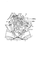
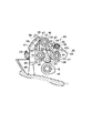
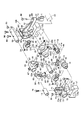
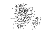
図1は、内燃機関、例えば複数気筒(図示しない)が直列に並ぶレシプロ式ガソリンエンジンのシリンダヘッド1の平面図、図2〜図5は同シリンダヘッド1のそれぞれ異なる側断面図を示している。このシリンダヘッド1の下面には、図2に示されるように気筒の配列にならって燃焼室2が長手方向に沿って形成されている。これら燃焼室2毎に、例えば2個づつ(一対)、吸気ポート3および排気ポート4(片側しか図示せず)が設けてある。またシリンダヘッド1の上部には、吸気ポート3を開閉する吸気バルブ5(往復バルブで構成される)、排気ポート4を開閉する排気バルブ6(往復バルブで構成される)がそれぞれ組付けられている。なお、複数の吸気バルブ5、複数の排気バルブ6には、いずれもバルブスプリング7で閉方向に付勢される常閉式が用いてある。このシリンダヘッド1の上部には、複数の吸気バルブ5、複数の排気バルブ6を駆動させる動弁系、例えばSOHC式の動弁系8が搭載されている。図6には同動弁系8を分解した斜視図が示されている。
FIG. 1 is a plan view of a
この動弁系8について説明すると、図1〜図6中10は、燃焼室2の頭上にシリンダヘッド1の長手方向に回転自在に配設されたカムシャフトである。11はこのカムシャフト10を挟む上部片側(シリンダヘッド幅方向片側)で上記カムシャフト10とほぼ平行に配置された回動可能な吸気側のロッカシャフト、12はその反対側に上記カムシャフト10とほぼ平行に配置された排気側のロッカシャフト、13は、例えばロッカシャフト11とロッカシャフト12間の上側の地点に、上記カムシャフト10とほぼ平行に配置された支持シャフト(本願の支持軸に相当)を示す。カムシャフト10は、エンジンのクランク出力により、図2中の矢印方向に沿って回転駆動される部品である。このカムシャフト10には、燃焼室2毎、吸気用カム15(1つ)と排気用カム16(2つ)が形成されている。具体的には、吸気用カム15は燃焼室2の頭上中央の地点となるシャフト部分に形成され、排気用カム16はその吸気用カム15を挟む両側の部分にそれぞれ形成してある(図1のみ図示)。このカムシャフト10の各部、例えば軸方向両端部、気筒間となるカム群間のシャフト部分などが、図4〜図6に示されるようにシリンダヘッド1の上記各部と対応する上面部分に立設してあるシリンダヘッド幅方向に延びる壁状の支持台17で回転自在に支持されている。17aは、そのカムシャフト10を支持する、支持台17の壁部中央に形成された軸受部を示している。
The
このうち排気側のロッカシャフト12には、図1、図2および図6に示されるように排気用カム16毎(排気バルブ6毎)、排気バルブ6駆動用の一対のロッカアーム18(片側しか図示せず)がそれぞれ回動自在に設けられている。これらロッカアーム18は、いずれも図1、図2および図6に示されるようにロッカシャフト12で回動自在に支持される部分、例えばロッカシャフト支持用ボス22を有し、同支持用ボス22を挟んだカムシャフト10側の端部(一端部)に、当接子となるローラ部材23を回転自在に有し、反対側の端部(他端部)に、排気バルブ6の駆動をなす駆動部分、例えばアジャストスクリュ部24を有した構造が用いられている。そして、図2および図3に示されるように各ロッカアーム18のローラ部材23がそれぞれ排気用カム16のカム面と転接し、反対側のアジャストスクリュ部27がそれぞれシリンダヘッド1の上部から突き出ている排気バルブ6の上部端(バルブステム端)に配置されている。
Among these, the
また吸気側のロッカシャフト11には、吸気用カム15毎に、複数(一対)の吸気バルブ5を一緒に駆動するロッカアーム機構19が設けられている。このロッカアーム機構19、さらには上記一対のロッカアーム18により、各吸気用カム15、排気用カム16が回転されると、所定の燃焼サイクル(例えば吸気行程、圧縮行程、爆発行程、排気行程の4サイクル)が得られるタイミングで、吸気バルブ5、排気バルブ6が開閉されるようにしてある。
Further, the
この吸気側のロッカアーム機構19には可変動弁装置20が採用されている。同可変動弁装置20を説明すると、同装置20を構成するロッカアーム機構19には、図1〜図3および図6に示されるようにロッカシャフト11に揺動自在に支持されるロッカアーム25(第1アームに相当)と、吸気用カム15で駆動されるセンタロッカアーム35(第2アームに相当)と、支持シャフト13に揺動自在に支持されるスイングカム45(第3アームに相当)とを組み合わせた構造が用いられている。
The intake side
このうちロッカアーム25には、例えば図6に示されるような複数(一対)の吸気バルブ5へ変位を伝える部分を二股形状にした構造が採用されている。例えばロッカアーム25は、中央に筒状のロッカシャフト支持用ボス26を有し、そのボス26を挟んだ一端側に、吸気バルブ5の駆動をなす駆動部分、例えばアジャストスクリュ部27をもつ一対のロッカアーム片29を並行に配置し、これらロッカアーム片29の他端部間に、当接子となるローラ部材30を回転自在に挟み込んだ構造が用いられている。なお、32はローラ部材30を回転自在に枢支するための短シャフトを示す。そして、図2に示されるように、組み上げられたロッカアーム25の各ロッカシャフト支持用ボス26がロッカシャフト11に揺動自在に嵌挿され、ローラ部材30をシリンダヘッド1の中央側に向け、残るアジャストスクリュ部27をそれぞれシリンダヘッド1の上部から突き出ている吸気バルブ5の上部端(バルブステム端)に配置させてある。
Of these, the
またセンタロッカアーム35には、図2、図3および図6に示されるように吸気用カム15のカム面と転接する転接子、例えばカムフォロア36と、同カムフォロア36を回転自在に支持する枠形のホルダ部37とをもつ、ほぼL形部材が用いられている。具体的には、センタロッカアーム35は、カムフォロア36を中心として、ホルダ部37から上方、具体的にはロッカシャフト11と支持シャフト13間へ向かって柱状に延びる中継用アーム部38と、ホルダ部37の側部から、一対のロッカアーム片29間で露出しているロッカシャフト部分11a(図8〜図11に図示)の下側へ延びる平板状の支点用アーム部39とを有して、L形に形成してある。そして、中継用アーム部38の先端(上端面)には、スイングカム45へ変位を伝える中継面として、例えばロッカシャフト11側が低く、支持シャフト13側が高くなるよう傾斜させた傾斜面40が形成してある。残る支点用アーム部39の先端部は、ロッカシャフト部分11aに支持されている。この支持には、例えば図2、図6および図8〜図11に示されるようにロッカシャフト部分11aに、支点用アーム部39と組み合うピン部材41を直径方向(径方向)に組付けた構造が用いられている。すなわち、ピン部材41には、下端部に球面状部41aが形成され、外周面におねじ部41cが形成された部品が用いられている。このピン部材41は、ロッカシャフト部分11aの上側に形成された据付座11b(例えば切欠部よりなる)から下側(径方向)へ貫通するよう、支点用アーム部39の先端部に向って進退可能に螺挿、さらには据付座11b上から突き出た端部をロック用ナット41bで締め付けることによって、ロッカシャフト部分11aに固定してある。なお、図示はしないが、ロッカシャフト部分41cのピン部材41が貫通する通孔はねじ孔で形成されている。そして、ロッカシャフト部分11bの下端部から突き出たピン端部は、支点用アーム部39に支持させてある。具体的には、支点用アーム部39の先端部上面には、ロッカシャフト部分11aから突き出た球面状部41aと回動(可動)可能に嵌まり合う半球面状の受け部42が形成されていて、同支持によりカムフォロア36が吸気用カム15で駆動されると、センタロッカアーム35が、ロッカシャフト11側を支点、すなわち球面状部41aと受け部42とが嵌まり合うピボット部を支点に、上下方向へ揺動するようにしてある。
2, 3, and 6, the
またロッカシャフト11の端部には、制御アクチュエータとして、例えば制御用モータ43(図6のみ図示)が接続されていて、制御用モータ43の作動により、ロッカシャフト11を所望に回動変位、例えば図8および図9に示されるピン部材41が略垂直方向に配置された姿勢から、図10および図11に示されるカムシャフト回転方向へ傾いた姿勢までの範囲で回動変位できるようにしている。つまり、制御モータ43、ピボット支持構造で構成される支点移動機構44(本願の可変機構に相当)により、センタロッカアーム35のロッカシャフト11側の支点を、同シャフト11の軸方向と交差する方向に移動(変位)できるようにしている。この移動がもたらすセンタロッカアーム35の位置ずれを利用して、図8〜図11に示されるようにカムフォロア36の吸気用カム15に対する転接位置(当接位置)が可変、すなわち吸気用カム15の回転方向前後へ変位できるようにしている。
Further, for example, a control motor 43 (shown only in FIG. 6) is connected to the end of the
一方、スイングカム45は、図2、図3および図6に示されるように支持シャフト13に回動自在に嵌挿される筒状のボス部46と、同ボス部46からローラ部材30(ロッカアーム25)へ向って延びるアーム部47と、同アーム部47の下部に形成した変位受け部48とを有して形成されている。このうちアーム部47の先端には、ロッカアーム25へ変位を伝える伝達面部として、例えば上下方向に延びるカム面49が形成されている。このカム面49がロッカアーム25のローラ部材30の外周面に転接させてある。また変位受け部48には、例えば図6に示されるようにアーム部47の下部のうち、カムシャフト10の直上となる下面部分に凹陥部51を形成し、同凹陥部51内に、シャフト10,11,12と同じ向きで、短シャフト52を回転自在に収めた構造が用いられている。さらに述べれば、凹陥部51の開放部から露出する短シャフト52の下部には、凹部53が形成されていて、同凹部53内に中継用アーム部38(センタロッカアーム35)の先端部が摺動自在に差し込まれている。また凹部53の底面には、傾斜面40をスライド可能に受け止める平面状の受け面53aが形成されている。
On the other hand, the
つまり、スイングカム45は、センタロッカアーム35の揺動変位を受けると、支持シャフト13が支点Xとし、凹部53をセンタロッカアーム35からの荷重が作用する作用点Yとし、カム面49がロッカアーム25を駆動させる力点Zとして、周期的に揺動する構造にしてあると同時に、カムフォロア36が吸気用カム15の所定位置から進角方向や遅角方向へ変位(センタロッカアーム35が吸気用カム15の移動方向前後へ変位)すると、該変位に伴うスイングアーム45の姿勢の変化から、吸気用カム15の位相が進角方向(あるいは遅角方向)へずれるようにしてある。
That is, when the
またカム面49には、例えば支持シャフト13の中心からの距離が変化する曲面(本願の変換部)が用いられている。これには、例えば図2中に示されるようにカム面49の上部側をベース円区間α、すなわち図2中に示されるように支持シャフト13の軸心を中心とした円弧面で形成された区間とし、下部側をリフト区間β、すなわち上記円弧に連続した反対向きの円弧面及びさらに反対向きの円弧面、例えば吸気用カム15のリフト域のカム形状と同じような円弧面で形成された区間とした曲面が用いられている。このカム面49により、カムフォロア36が吸気用カム15の所定位置から進角方向へ変位(センタロッカアーム35の支点位置が変位)すると、ローラ部材30が接するカム面49の領域が変化、詳しくはローラ部材30が行き交うベース円区間αとリフト区間βの比率が変化するようにしてある。この進角方向の位相変化を伴いながら行われる区間α,βの比率の変化により、吸気バルブ5の開閉タイミングが開弁時期を揃えつつ連続的に可変されたり、同時に吸気バルブ5のバルブリフト量が連続的に可変されたりしている。
The
またピン部材41の上端部には、回動操作を受ける受け部として例えばプラス形の凹部55(図6にのみ図示)が形成されている。このピン部材41の凹部55と、先に述べたピン部材41の螺挿構造と、先に述べたピン部材41をロックするナット41bとにより、気筒毎に吸気バルブ5の開弁時期を調整できるようにしている(ピン部材41をドライバ工具で前進方向や後退方向に変位させる螺挿作業、ナット41bのロックを解除したりロックしたりする作業による)。
Further, for example, a plus-shaped concave portion 55 (shown only in FIG. 6) is formed at the upper end portion of the
図1〜図3、図6中58は、ロッカアーム機構19の各アーム間を密接、すなわち吸気カム15、センタロッカアーム35およびスイングカム45の相互間を密接する方向に付勢するためのプッシャである。プッシャ58は、例えば図2および図3に示されるように上端部が開口した縦型の有底筒状のホルダ部59と、同ホルダ部材59の開口部に上下動自在に嵌挿された下端が開放した有底筒状の可動部60と、ホルダ部59内に該ホルダ部59の内底面と可動部60の内底面との間に渡り収められたスプリング部材、例えばコイルスプリング61とを有して構成されている。このプッシャ58が、スイングカム45を下方から上方へ向かい付勢する姿勢で、シリンダブロック1上に配置されている。すなわち、プッシャ58は、例えばボス部46の外周面からアーム部47とは反対側へ向って突き出るように形成されたリブ状の受け部67とその下側のシリンダヘッド1上面部分に形成されている台部68との間に介在させてある。具体的にはプッシャ58は、例えば図3および図6に示されるようにホルダ部61の一部に、例えばホルダ部59の下部側へ延びる据付け脚63を形成し、この据付け脚63の中段部分に、支点用として、排気側のロッカシャフト12と嵌合可能なC字状の嵌込み部64を形成し、据付け脚63の下段に、反力受用として受け座65を形成した構造が用いられている。なお、受け座65は、例えば据付け脚63の先端部をホルダ部59の下部側と並ぶ向きに曲げて形成してある。そして、このプッシャ58が、可動部60の先端面に形成されている突当て部60aを受け部67の下面に突き当て、嵌込み部64を受け部67の直下のロッカシャフト12部分に嵌合させ、ロッカシャフト12部分の下側の台部68上に受け座65を載せた姿勢で、受け部67とシリンダヘッド1上面との間に介在させてある。もちろん、プッシャ58は、受け部67と台部68との間に取付けると、可動部60が押込まれるようにしてある。そして、この可動部60の押込みがもたらすコイルスプリング61の圧縮変形により、支点X側から、スイングカム45を下方から上方へ向かう方向から付勢して、常時、各アーム同士を離れることがないよう密接させている(ロストモーション抑制のため)。
1-3 and FIG. 6, 58 is a pusher for urging the arms of the
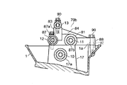
こうした動弁系8のロッカシャフト11(吸気側)、ロッカシャフト12(排気側)および支持シャフト13の各部、例えば軸方向両端部、気筒間となるカム群間のシャフト部分など、吸気側のロッカアーム機構19や排気側の一対のロッカアーム18と隣接した部分や、吸気側のロッカアーム機構19と排気側の一対のロッカアーム18との間の部分などが、図1に示されるように保持部材、例えば二種類の保持部材70a,70bによって保持されている。
The rocker arm on the intake side such as the rocker shaft 11 (intake side), rocker shaft 12 (exhaust side) and
この保持構造について説明すると、保持部材70aは、ロッカシャフト11の近くに固定するためのスペースがシリンダヘッド上面において確保される地点、例えばシャフト端を保持するのに適した部品である。残る保持部材70bは、ロッカシャフト11の近くでは固定するためのスペースの確保ができない地点、例えば気筒間(カム群間)のシャフト部分を保持するのに適した部品である。
This holding structure will be described. The holding
このうち保持部材70aは、図6に示されるようにシリンダヘッド1の前後方向端に配置された支持台17に載置可能な本体部72をもつ。この本体部72の側部には、ロッカシャフト11,12端に嵌まる嵌挿部73,74がそれぞれ形成されている。なお、嵌挿部73,74のうち、例えば排気側のロッカシャフト12端が嵌まる片側の嵌挿部73は、筒状に形成され、吸気側のロッカシャフト11端が嵌まる片側の嵌挿部74は、ロッカシャフト11端を回動可能に収める有底筒状に形成してある。また本体部72の上部、例えば嵌挿部73,74間からは、支持シャフト13端を下側から支える柱状の受け部75が突き出ている。そして、この支持シャフト13端が、上側から支持シャフト13を貫通して受け部75へ螺挿される締結具、例えばボルト部材76により、受け部75に固定されている。こうした固定構造ならびに嵌挿構造により、支持シャフト13、両ロッカシャフト11,12の端部を、所定の間隔を保ったまま、保持部材70aで保持させている。
Among these members, the holding
また保持部材70aは、保持部材70aが配置される部位がシリンダヘッド1の前後方向端であることを考慮(排気側および吸気側の双方で、固定スペースが確保しやすい部位)して、片側の固定構造には、例えば図5および図6に示されるように嵌挿部73の上面部分に固定用座面77aを形成し、嵌挿部73の下面部分に本体部72下面と面一な設置面77bを形成し、固定用座面77aからロッカシャフト12を通じて設置面77bへ至る通路77cを形成した構造が用いられている。また残る片側を固定する構造には、例えば図5および図6に示されるように嵌挿部74の底部分を形成する部分に軸方向外側へ張り出るボス部79を形成し、同ボス部79の上面に固定用座面79aを形成し、ボス部79の下面に本体部72下面と面一な設置面79bを形成し、ボス部79内に、固定用座面79aと設置面79b間を連絡する通路79cを形成した構造が用いてある。
Further, the holding
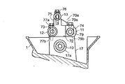
保持部材70bは、図6に示されるように吸気側のロッカシャフト11に摺動可能に嵌まる筒形の嵌挿部81と、排気側のロッカシャフト12に嵌まる筒形の嵌挿部82と、支持シャフト13を下側から支える壁状の受け部83とを一体に結合させてなる本体部84をもつ。この本体部84の各部(嵌挿部81,82,受け部83)が、図1に示されるようにそれぞれ気筒間の部位、すなわちロッカアーム機構19間のロッカシャフト11部分、一対のロッカアーム18間のロッカシャフト12部分、スイングカム45のボス部46間の支持シャフト13部分に介在されている。そして、受け部83上の支持シャフト13部分は、上側から支持シャフト13を貫通して受け部83へ螺挿される締結具、例えばボルト部材86により、受け部83に固定され、各シャフト11〜13の中間部分を、所定の間隔を保ったまま、保持部材70bで保持させている。
As shown in FIG. 6, the holding
こうした保持部材70bによる各シャフト11〜13の中間部の保持、先に述べた保持部材70aによる各シャフト11〜13端の保持により、図7に示されるようにロッカアーム機構19(可変動弁装置20)はもちろん、同ロッカアーム機構19を含むシリンダヘッド1に搭載される動弁系8の部品を一つの構造体Xにモジュール化させている。
By holding the intermediate portions of the
また保持部材70bは、同保持部材70bが配置される部位がシリンダヘッド1の前後方向中間であることを考慮(例えば気筒やウォータジャケットなどの影響で、吸気側、排気側のいずれか一方を固定するスペースがロッカシャフト近くで確保しにくく部位)、ここでは吸気側のロッカシャフト11の近くで固定スペースが確保しにくいシリンダヘッド構造を考慮して、排気側の固定構造には、例えば図4および図6に示されるように嵌挿部81の上面部分に固定用座面87aを形成し、嵌挿部81,82の下部に設置面87bを形成し、さらに固定用座面87aからロッカシャフト12を通じて設置面87bに至る通路87cを形成した構造が用いられている。残る吸気側の固定構造には、例えば図4および図6に示されるように固定が行えないロッカシャフト12周辺を避けたシリンダヘッド1の側縁側(幅方向片側)、例えばロッカシャフト12から離れたシリンダヘッド1の側縁部の近くに形成された座面1aで固定が行えるようにした構造が用いられている。具体的には同固定構造には、本体部84の片側である嵌挿部81の側部に、座面1aへ向って延びる延出部88を形成し、同延出部88の端部に、上下方向に沿って固定用の通孔89を形成した構造が用いられている。
In addition, the holding
こうした固定構造を用いて構造体Xは、図7に示されるようにシリンダヘッド1の上面に固定させてある。すなわち、構造体Xは、図4および図5に示されるように各保持部材70aが、シリンダヘッド1の前後方向両側に配置されている支持台17の上面に形成されたセット面17bに載置され、各保持部材70bが、シリンダヘッド1の前後方向中間に配置された支持台17の上面に形成されたセット面17bや座面1aに載置されてから、各保持部材70aの座面77a,79aから支持台17のセット面17bへボルト部材90が螺挿され、各保持部材70bの固定用座面87aから支持台17のセット面17bへボルト部材90が螺挿され、さらに通孔89から座面1aへボルト部材90が螺挿されることによって、吸気側のロッカシャフト11の直側方を避けながら、シリンダヘッド1の上面に固定されている。
Using such a fixing structure, the structure X is fixed to the upper surface of the
また図1に示されるように各保持部材70bの嵌挿部82の下部とこれに対応する支持台17の上面部分には、構造体Xをシリンダヘッド1に搭載するときの当初の位置決めを行う位置決め用ノックピン部92が形成されている。そして、各保持部材70a,70bの延出部88端を固定するときは、延出部88とは反対側の離れた地点にあるノックピン部92で位置決められてから固定するようにしている。
Further, as shown in FIG. 1, initial positioning when the structure X is mounted on the
なお、図2中94は、吸気側のロッカアーム片29,29間を通じて、シリンダヘッド1に装着された点火プラグ(燃焼室2内の混合気を点火する機器)を示す。
2 denotes a spark plug (a device for igniting the air-fuel mixture in the combustion chamber 2) attached to the
つぎに、このように構成された可変動弁装置20の作用を説明する。
Next, the operation of the variable
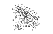
まず、吸気バルブ5の開閉に伴うロッカアーム機構19の動きについて説明すれば、今、図2に示されるようにカムシャフト10が回転(矢印方向)しているとする。
First, the movement of the
このとき、図2に示されるようにセンタロッカアーム35のカムフォロア36は、ロッカアーム片29間に配置されている吸気用カム15を受けていて、同カム15のカムプロフィールにならい駆動される。すると、センタロッカアーム35は、ロッカシャフト11側のピボット部を支点として上下方向へ揺動される。この揺動変位が、センタロッカアーム35の直上にあるスイングカム45へ伝わる。
At this time, as shown in FIG. 2, the
ここで、スイングカム45は、一端部が支持シャフト13で揺動自在に支持され、他端部がロッカアーム25のローラ部材30に転接されている。この状態から、下部に有る回転自在な短シャフト52に形成した受け面53aで、中継用アーム部38先端の傾斜面40を受けている。これにより、スイングカム45は、傾斜面40をすべりながら、該傾斜面40で押し上げられたり下降したりするといった挙動を繰り返す。このスイングカム45の揺動により、カム面49は上下方向へ駆動される。
Here, one end portion of the
このとき、カム面49には、ローラ部材30が転接しているから、カム面49でローラ部材30を周期的に押圧する。この押圧を受けてロッカアーム25は、ロッカシャフト11を支点に駆動(揺動)され、複数(一対)の吸気バルブ5を一度に開閉させる。
At this time, since the
こうした運転中、制御モータ43の作動により、ロッカシャフト11を回動させ、例えば最大バルブリフト量が確保される地点に、センタロッカアーム35の支点位置を移動させる。すると、支点位置の変位から、センタロッカアーム35のカムフォロア36は、図2に示されるように吸気用カム15上を変位して、スイングカム45のカム面49を垂直に近い角度(ベース円区間αにあるとき)となる姿勢に位置決める。
During such operation, the operation of the
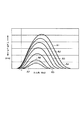
これにより、カム面49は、ローラ部材30が行き交う領域(比率)が、最大のバルブリフト量をもたらす領域、すなわち図8に示される最も短いベース円区間αと図9に示される最も長いリフト区間βに設定される。すると、吸気バルブ5は、狭いベース円区間αと最も長いリフト区間βとがなすカム面部分で駆動されるロッカアーム25にしたがい、図12中のA1の線図に示されるような最大バルブリフト量、さらには所望とする開閉タイミングで開閉される。
As a result, the
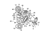
この状態から、吸気用カム15の位相を可変するときは、制御モータ43の作動により、ロッカシャフト11を最大バルブリフト量が確保される位置(図8および図9中のピン部材41位置)から、時計方向へ回動させる。これにより、センタロッカアーム35のピボット部(支点位置)は、カムシャフト10側へずれる。
From this state, when the phase of the
ここで、センタロッカアーム35は、スイングアーム45へ変位を伝える部分が、中継用アーム部38の傾斜面40と同傾斜面40と面接触する短シャフト52の受け面53aとにより形成され、吸気用カム15を受ける部分が吸気用カム15と転接するカムフォロア36で形成されているから、上記変位(ずれ)を受けると、センタロッカアーム35の全体は、カムフォロア36の転接位置が吸気用カム15の進角方向へ進むように変位(ずれ)する。この転接位置の変化により、可変しようとするカム位相の開弁時期が、ピボット部(支点位置)の可変量に応じて早まる。
Here, the
また傾斜面40も、支点の移動を受けて、当初の位置から受け面53a上を進角方向へ変位(スライド)する。これにより、スイングカム45は、図10および図11に示されるようにカム面49が下側へ傾く姿勢に変わる。この傾きが大きくなるにしたがい、ローラ部材30が行き交うカム面49の領域は、ベース円区間αが次第に長く、リフト区間βが次第に短くなる比率の領域に変わる。そして、この可変したカム面49のカムプロフィールがローラ部材30へ伝達され、ロッカアーム25を、開弁時期を早めながら揺動駆動する。これにより、吸気バルブ5の開閉タイミングは、センタロッカアーム35の支点位置の移動にしたがい、図9中に示されるように最大バルブリフト量A1から、ピン部材41が傾くことで得られる最小バルブリフト量A7まで、最大バルブリフト時とほぼ同じ開弁時期から開弁するタイミングを保ちながら、連続的に可変制御される。なお、図10および図11は、この可変制御のうち、最小バルブリフト量A7にしたときの状態を示している。
The
したがって、ロッカアーム25、センタロッカアーム35およびスイングカム45を組み合わせた単一のロッカアーム機構19だけで、開弁時期よりも閉弁時期を大きくした可変ができ、開弁時期をほぼ揃えたカム位相の可変ができる。しかも、スイングカム45には、支持シャフト13からカム面49までの距離を変化させて、ロッカアーム25へ伝わるカム位相をバルブリフト量と共に連続的に可変させる構造が用いてあるので、開弁時期をほぼ揃えたタイミングで連続的に吸気バルブ5の開閉タイミングおよびバルブのリフト量の可変を同時に行うことができる。こうした開弁時期をほぼ揃えたタイミングでのバルブリフト量、開閉タイミングの連続的な可変は、ロスを抑えながら吸入空気を気筒内へ吸入させることができ、特にポンピングロスの低減に優れた効果を発揮する。
Therefore, the valve closing timing can be made larger than the valve opening timing only by a single
そのうえ、ロッカアーム機構19の各部品は、保持部材70a,70bを用いて、共通部品である吸気側のロッカシャフト11、排気側のロッカシャフト12、支持シャフト13を保持してモジュール化させて、シリンダヘッド1へ固定する構造としてあるから、気筒間の動作タイミングを調整するときは、図7に示されるようにシリンダヘッド1に組付ける前の吸・排気バルブ5,6側からの負荷が無い構造体Xのままで行えるから、調整は容易である。さらに保持部材70bは、延出部88の形成により、広いスパンでシリンダヘッド1に固定される構造なので、高い安定性のもとで構造体Xのシリンダヘッド1への組込みができる。
In addition, each part of the
特にロッカシャフト11を回動変位させてセンタロッカアーム35の支点を変位させる構造とした場合、排気側ロッカシャフト12と吸気側ロッカシャフト11とを保持する保持部材70bは、吸気側ロッカシャフト11に対して排気側ロッカシャフト12の反対側に延在する延出部88の端部がシリンダヘッド1に固定されているため、延出部88の端部をシリンダヘッド1に固定するノックピン90を中心とした保持部材70bのぶれは、排気側ロッカシャフト12を保持する嵌挿部82よりも吸気側ロッカシャフト11を保持する嵌挿部81の方が小さくなり、該嵌挿部81の変位が小さく抑えられるから、ロッカシャフト11と保持部材70bとの間で、容易にロッカシャフト11のスムーズな動きに必要なクリアランスを確保できる。
In particular, when the
また、保持部材70bの延出部88をシリンダヘッド1に固定するノックピン90取付部にプッシュノック92を設けることにより、保持部材70b自体の変位が抑制されるため、吸気側ロッカシャフト11の変位がさらに抑制される。
Further, by providing the push knock 92 to the mounting portion of the
また、本発明に位相可変装置を併用しても、位相可変量は小さくてすむため、可変する応答遅れが生じず、十分な燃費の改善を図ることができる。 Even if the phase varying device is used in combination with the present invention, the amount of phase variation can be small, so that a variable response delay does not occur, and sufficient fuel consumption can be improved.
なお、本発明は上述した一実施形態に限定されるものではなく、本発明の主旨を逸脱しない範囲内で種々変更して実施しても構わない。例えば上述した一実施形態では、保持部材の吸気側の端部を延出させた構造を挙げたが、これに限らず、シリンダヘッド構造によっては、排気側の端部を延出させた構造でもよい。 The present invention is not limited to the above-described embodiment, and various modifications may be made without departing from the spirit of the present invention. For example, in the above-described embodiment, the structure in which the end portion on the intake side of the holding member is extended has been described. However, the structure is not limited to this, and the end portion on the exhaust side may be extended depending on the cylinder head structure. Good.
5…吸気バルブ、6…排気バルブ、10…カムシャフト、11…吸気側のロッカシャフト、12…排気側のロッカシャフト、13…支持シャフト(支持軸)、19…ロッカアーム機構、20…可変動弁装置、25…ロッカアーム(第1アーム)、35…センタロッカアーム(第2アーム)、44…支点移動機構(可変機構)、45…スイングカム(第3アーム)、49…カム面(伝達面部)、70a,70b…保持部材、88…延出部、92…ブッシュノック、X…モジュール化した構造体、α,β…ベース円区間,リフト区間(変換部)。
DESCRIPTION OF
Claims (4)
前記カムシャフトと並行に配置された吸気および排気ロッカシャフトと、
前記カムシャフトに形成されたカムにより駆動されて吸気又は排気バルブを開閉するロッカアーム機構と
を有する内燃機関の可変動弁装置において、
前記ロッカアーム機構は、
前記ロッカシャフトに揺動自在に支持され吸気又は排気バルブを駆動可能な第1アームと、
前記カムと当接して該カムにより駆動され前記ロッカシャフト側を支点として揺動する第2アームと、
前記ロッカシャフトの近傍に配置された支持軸に揺動自在に設けられ、前記第2アームの変位を受け、前記第2アームの支点移動がもたらす該第2アームの姿勢変化にしたがい、前記カムの位相を可変させて前記第1アームを駆動する第3アームと、
前記カムとの当接位置を該カムの移動方向前後へ変位させるべく、前記第2アームの前記ロッカシャフト側の前記支点を変位させる可変機構と、
前記吸気および排気ロッカシャフトと前記支持軸とを保持して前記ロッカアーム機構をモジュール化する保持部材とを有し、
前記保持部材を介して前記ロッカアーム機構が前記シリンダヘッドに固定される
ことを特徴とする内燃機関の可変動弁装置。 A camshaft rotatably provided on a cylinder head of an internal combustion engine;
An intake and exhaust rocker shaft arranged in parallel with the camshaft;
A variable valve operating apparatus for an internal combustion engine having a rocker arm mechanism that is driven by a cam formed on the camshaft to open and close an intake or exhaust valve;
The rocker arm mechanism is
A first arm supported swingably on the rocker shaft and capable of driving an intake or exhaust valve;
A second arm that abuts on the cam and is driven by the cam and swings about the rocker shaft side;
The cam is provided on a support shaft disposed in the vicinity of the rocker shaft so as to be swingable. The displacement of the second arm causes a change in the posture of the second arm caused by movement of the fulcrum of the second arm. A third arm that drives the first arm with a variable phase;
A variable mechanism for displacing the fulcrum of the second arm on the rocker shaft side so as to displace the abutting position with the cam in the longitudinal direction of the cam;
A holding member that holds the intake and exhaust rocker shafts and the support shaft and modularizes the rocker arm mechanism;
The variable valve operating apparatus for an internal combustion engine, wherein the rocker arm mechanism is fixed to the cylinder head via the holding member.
ことを特徴とする請求項1に記載の内燃機関の可変動弁装置。 The holding member has an extending portion extending from one side of the intake or exhaust side rocker shaft to the side edge side of the cylinder head, and an end portion of the extending portion and the other side separated from the end portion The variable valve operating apparatus for an internal combustion engine according to claim 1, wherein a point on the side is fixed to the cylinder head.
前記保持部材は、前記第1アームを支持するロッカシャフト側から前記シリンダヘッドの側縁側へ延びた延出部を有し、同延出部の端部と該端部から離れた前記保持部材の反対側の端部が前記シリンダヘッドに固定され、
さらに前記保持部材の延出部は、前記保持部材の反対側が前記シリンダヘッドに位置決められてから固定されるようにしてある
ことを特徴とする請求項2に記載の内燃機関の可変動弁装置。 The variable mechanism is configured to displace a fulcrum of the second arm on the rocker shaft side when the rocker shaft supporting the first arm is rotationally displaced.
The holding member has an extending portion extending from a rocker shaft side supporting the first arm to a side edge side of the cylinder head, and an end portion of the extending portion and the holding member separated from the end portion. The opposite end is fixed to the cylinder head,
The variable valve operating apparatus for an internal combustion engine according to claim 2, wherein the extending portion of the holding member is fixed after the opposite side of the holding member is positioned on the cylinder head.
前記伝達面部は、前記支持軸の中心からの距離が変化する変換部を備え、
前記当接位置の変位がもたらす前記第2アームの姿勢変化から、前記支持軸から前記伝達面部までの距離を変化させて、前記第1アームに伝わるカムの位相が、前記バルブのバルブリフト量と共に連続的に可変されるようにしてある
ことを特徴とする請求項1ないし請求項3にいずれか一つに記載の内燃機関の可変動弁装置。 The third arm has a transmission surface portion in contact with the first arm to drive the first arm,
The transmission surface portion includes a conversion portion whose distance from the center of the support shaft changes,
The phase of the cam transmitted to the first arm is changed together with the valve lift amount of the valve by changing the distance from the support shaft to the transmission surface portion from the change in posture of the second arm caused by the displacement of the contact position. The variable valve operating device for an internal combustion engine according to any one of claims 1 to 3, wherein the variable valve device is continuously variable.
Priority Applications (1)
| Application Number | Priority Date | Filing Date | Title |
|---|---|---|---|
| JP2004117814A JP4118248B2 (en) | 2004-04-13 | 2004-04-13 | Variable valve operating device for internal combustion engine |
Applications Claiming Priority (1)
| Application Number | Priority Date | Filing Date | Title |
|---|---|---|---|
| JP2004117814A JP4118248B2 (en) | 2004-04-13 | 2004-04-13 | Variable valve operating device for internal combustion engine |
Related Child Applications (1)
| Application Number | Title | Priority Date | Filing Date |
|---|---|---|---|
| JP2005319836A Division JP4195463B2 (en) | 2005-11-02 | 2005-11-02 | Variable valve operating device for internal combustion engine |
Publications (2)
| Publication Number | Publication Date |
|---|---|
| JP2005299538A true JP2005299538A (en) | 2005-10-27 |
| JP4118248B2 JP4118248B2 (en) | 2008-07-16 |
Family
ID=35331387
Family Applications (1)
| Application Number | Title | Priority Date | Filing Date |
|---|---|---|---|
| JP2004117814A Expired - Fee Related JP4118248B2 (en) | 2004-04-13 | 2004-04-13 | Variable valve operating device for internal combustion engine |
Country Status (1)
| Country | Link |
|---|---|
| JP (1) | JP4118248B2 (en) |
Cited By (4)
| Publication number | Priority date | Publication date | Assignee | Title |
|---|---|---|---|---|
| JP2008202478A (en) * | 2007-02-19 | 2008-09-04 | Mitsubishi Motors Corp | Valve operating device for internal combustion engine |
| JP2008202581A (en) * | 2007-02-22 | 2008-09-04 | Mitsubishi Motors Corp | Valve mechanism of internal combustion engine |
| US7658172B2 (en) | 2006-10-31 | 2010-02-09 | Mitsubishi Jidosha Kogyo Kabushiki Kaisha | Valve unit of internal combustion engine |
| CN101994533A (en) * | 2010-09-18 | 2011-03-30 | 中国兵器工业集团第七○研究所 | Single over head camshaft three-rocker four-valve diesel engine distribution device |
-
2004
- 2004-04-13 JP JP2004117814A patent/JP4118248B2/en not_active Expired - Fee Related
Cited By (4)
| Publication number | Priority date | Publication date | Assignee | Title |
|---|---|---|---|---|
| US7658172B2 (en) | 2006-10-31 | 2010-02-09 | Mitsubishi Jidosha Kogyo Kabushiki Kaisha | Valve unit of internal combustion engine |
| JP2008202478A (en) * | 2007-02-19 | 2008-09-04 | Mitsubishi Motors Corp | Valve operating device for internal combustion engine |
| JP2008202581A (en) * | 2007-02-22 | 2008-09-04 | Mitsubishi Motors Corp | Valve mechanism of internal combustion engine |
| CN101994533A (en) * | 2010-09-18 | 2011-03-30 | 中国兵器工业集团第七○研究所 | Single over head camshaft three-rocker four-valve diesel engine distribution device |
Also Published As
| Publication number | Publication date |
|---|---|
| JP4118248B2 (en) | 2008-07-16 |
Similar Documents
| Publication | Publication Date | Title |
|---|---|---|
| JP4221327B2 (en) | Variable valve operating device for internal combustion engine | |
| CN100460631C (en) | Variable valve gear for internal combustion engines | |
| JP4118248B2 (en) | Variable valve operating device for internal combustion engine | |
| JP4195463B2 (en) | Variable valve operating device for internal combustion engine | |
| JP4293167B2 (en) | Variable valve operating device for internal combustion engine | |
| JP4293168B2 (en) | Variable valve operating device for internal combustion engine | |
| US7168404B2 (en) | Variable valve apparatus of internal combustion engine | |
| US7234426B2 (en) | Variable valve apparatus of internal combustion engine | |
| JP4180014B2 (en) | Variable valve operating device for internal combustion engine | |
| JP4180011B2 (en) | Variable valve operating device for internal combustion engine | |
| JP4180013B2 (en) | Variable valve operating device for internal combustion engine | |
| JP5042963B2 (en) | Variable valve operating device for internal combustion engine | |
| JP5148450B2 (en) | Variable valve operating device for internal combustion engine | |
| JP5148449B2 (en) | Variable valve operating device for internal combustion engine | |
| JP5148451B2 (en) | Variable valve operating device for internal combustion engine | |
| JP4180012B2 (en) | Variable valve operating device for internal combustion engine | |
| JP4225294B2 (en) | Variable valve operating device for internal combustion engine | |
| JP2007107430A (en) | Variable valve operating device for internal combustion engine |
Legal Events
| Date | Code | Title | Description |
|---|---|---|---|
| A621 | Written request for application examination |
Free format text: JAPANESE INTERMEDIATE CODE: A621 Effective date: 20060831 |
|
| TRDD | Decision of grant or rejection written | ||
| A977 | Report on retrieval |
Free format text: JAPANESE INTERMEDIATE CODE: A971007 Effective date: 20080327 |
|
| A01 | Written decision to grant a patent or to grant a registration (utility model) |
Free format text: JAPANESE INTERMEDIATE CODE: A01 Effective date: 20080401 |
|
| A61 | First payment of annual fees (during grant procedure) |
Free format text: JAPANESE INTERMEDIATE CODE: A61 Effective date: 20080422 |
|
| R150 | Certificate of patent or registration of utility model |
Ref document number: 4118248 Country of ref document: JP Free format text: JAPANESE INTERMEDIATE CODE: R150 Free format text: JAPANESE INTERMEDIATE CODE: R150 |
|
| FPAY | Renewal fee payment (event date is renewal date of database) |
Free format text: PAYMENT UNTIL: 20110502 Year of fee payment: 3 |
|
| FPAY | Renewal fee payment (event date is renewal date of database) |
Free format text: PAYMENT UNTIL: 20110502 Year of fee payment: 3 |
|
| FPAY | Renewal fee payment (event date is renewal date of database) |
Free format text: PAYMENT UNTIL: 20120502 Year of fee payment: 4 |
|
| R250 | Receipt of annual fees |
Free format text: JAPANESE INTERMEDIATE CODE: R250 |
|
| FPAY | Renewal fee payment (event date is renewal date of database) |
Free format text: PAYMENT UNTIL: 20130502 Year of fee payment: 5 |
|
| R250 | Receipt of annual fees |
Free format text: JAPANESE INTERMEDIATE CODE: R250 |
|
| FPAY | Renewal fee payment (event date is renewal date of database) |
Free format text: PAYMENT UNTIL: 20140502 Year of fee payment: 6 |
|
| R250 | Receipt of annual fees |
Free format text: JAPANESE INTERMEDIATE CODE: R250 |
|
| R250 | Receipt of annual fees |
Free format text: JAPANESE INTERMEDIATE CODE: R250 |
|
| R250 | Receipt of annual fees |
Free format text: JAPANESE INTERMEDIATE CODE: R250 |
|
| R250 | Receipt of annual fees |
Free format text: JAPANESE INTERMEDIATE CODE: R250 |
|
| R250 | Receipt of annual fees |
Free format text: JAPANESE INTERMEDIATE CODE: R250 |
|
| R250 | Receipt of annual fees |
Free format text: JAPANESE INTERMEDIATE CODE: R250 |
|
| R250 | Receipt of annual fees |
Free format text: JAPANESE INTERMEDIATE CODE: R250 |
|
| R250 | Receipt of annual fees |
Free format text: JAPANESE INTERMEDIATE CODE: R250 |
|
| S531 | Written request for registration of change of domicile |
Free format text: JAPANESE INTERMEDIATE CODE: R313531 |
|
| R250 | Receipt of annual fees |
Free format text: JAPANESE INTERMEDIATE CODE: R250 |
|
| R350 | Written notification of registration of transfer |
Free format text: JAPANESE INTERMEDIATE CODE: R350 |
|
| R250 | Receipt of annual fees |
Free format text: JAPANESE INTERMEDIATE CODE: R250 |
|
| LAPS | Cancellation because of no payment of annual fees |