JP2005299418A - Exhaust gas purification system control method and exhaust gas purification system - Google Patents
Exhaust gas purification system control method and exhaust gas purification system Download PDFInfo
- Publication number
- JP2005299418A JP2005299418A JP2004113375A JP2004113375A JP2005299418A JP 2005299418 A JP2005299418 A JP 2005299418A JP 2004113375 A JP2004113375 A JP 2004113375A JP 2004113375 A JP2004113375 A JP 2004113375A JP 2005299418 A JP2005299418 A JP 2005299418A
- Authority
- JP
- Japan
- Prior art keywords
- exhaust gas
- regeneration
- control
- filter
- water temperature
- Prior art date
- Legal status (The legal status is an assumption and is not a legal conclusion. Google has not performed a legal analysis and makes no representation as to the accuracy of the status listed.)
- Granted
Links
Images

Classifications
-
- F—MECHANICAL ENGINEERING; LIGHTING; HEATING; WEAPONS; BLASTING
- F02—COMBUSTION ENGINES; HOT-GAS OR COMBUSTION-PRODUCT ENGINE PLANTS
- F02D—CONTROLLING COMBUSTION ENGINES
- F02D41/00—Electrical control of supply of combustible mixture or its constituents
- F02D41/02—Circuit arrangements for generating control signals
- F02D41/021—Introducing corrections for particular conditions exterior to the engine
- F02D41/0235—Introducing corrections for particular conditions exterior to the engine in relation with the state of the exhaust gas treating apparatus
- F02D41/027—Introducing corrections for particular conditions exterior to the engine in relation with the state of the exhaust gas treating apparatus to purge or regenerate the exhaust gas treating apparatus
- F02D41/029—Introducing corrections for particular conditions exterior to the engine in relation with the state of the exhaust gas treating apparatus to purge or regenerate the exhaust gas treating apparatus the exhaust gas treating apparatus being a particulate filter
-
- F—MECHANICAL ENGINEERING; LIGHTING; HEATING; WEAPONS; BLASTING
- F01—MACHINES OR ENGINES IN GENERAL; ENGINE PLANTS IN GENERAL; STEAM ENGINES
- F01N—GAS-FLOW SILENCERS OR EXHAUST APPARATUS FOR MACHINES OR ENGINES IN GENERAL; GAS-FLOW SILENCERS OR EXHAUST APPARATUS FOR INTERNAL-COMBUSTION ENGINES
- F01N3/00—Exhaust or silencing apparatus having means for purifying, rendering innocuous, or otherwise treating exhaust
- F01N3/02—Exhaust or silencing apparatus having means for purifying, rendering innocuous, or otherwise treating exhaust for cooling, or for removing solid constituents of, exhaust
- F01N3/021—Exhaust or silencing apparatus having means for purifying, rendering innocuous, or otherwise treating exhaust for cooling, or for removing solid constituents of, exhaust by means of filters
- F01N3/023—Exhaust or silencing apparatus having means for purifying, rendering innocuous, or otherwise treating exhaust for cooling, or for removing solid constituents of, exhaust by means of filters using means for regenerating the filters, e.g. by burning trapped particles
- F01N3/0231—Exhaust or silencing apparatus having means for purifying, rendering innocuous, or otherwise treating exhaust for cooling, or for removing solid constituents of, exhaust by means of filters using means for regenerating the filters, e.g. by burning trapped particles using special exhaust apparatus upstream of the filter for producing nitrogen dioxide, e.g. for continuous filter regeneration systems [CRT]
-
- F—MECHANICAL ENGINEERING; LIGHTING; HEATING; WEAPONS; BLASTING
- F01—MACHINES OR ENGINES IN GENERAL; ENGINE PLANTS IN GENERAL; STEAM ENGINES
- F01N—GAS-FLOW SILENCERS OR EXHAUST APPARATUS FOR MACHINES OR ENGINES IN GENERAL; GAS-FLOW SILENCERS OR EXHAUST APPARATUS FOR INTERNAL-COMBUSTION ENGINES
- F01N3/00—Exhaust or silencing apparatus having means for purifying, rendering innocuous, or otherwise treating exhaust
- F01N3/02—Exhaust or silencing apparatus having means for purifying, rendering innocuous, or otherwise treating exhaust for cooling, or for removing solid constituents of, exhaust
- F01N3/021—Exhaust or silencing apparatus having means for purifying, rendering innocuous, or otherwise treating exhaust for cooling, or for removing solid constituents of, exhaust by means of filters
- F01N3/023—Exhaust or silencing apparatus having means for purifying, rendering innocuous, or otherwise treating exhaust for cooling, or for removing solid constituents of, exhaust by means of filters using means for regenerating the filters, e.g. by burning trapped particles
- F01N3/0235—Exhaust or silencing apparatus having means for purifying, rendering innocuous, or otherwise treating exhaust for cooling, or for removing solid constituents of, exhaust by means of filters using means for regenerating the filters, e.g. by burning trapped particles using exhaust gas throttling means
-
- F—MECHANICAL ENGINEERING; LIGHTING; HEATING; WEAPONS; BLASTING
- F02—COMBUSTION ENGINES; HOT-GAS OR COMBUSTION-PRODUCT ENGINE PLANTS
- F02D—CONTROLLING COMBUSTION ENGINES
- F02D41/00—Electrical control of supply of combustible mixture or its constituents
- F02D41/02—Circuit arrangements for generating control signals
- F02D41/021—Introducing corrections for particular conditions exterior to the engine
- F02D41/0235—Introducing corrections for particular conditions exterior to the engine in relation with the state of the exhaust gas treating apparatus
- F02D41/024—Introducing corrections for particular conditions exterior to the engine in relation with the state of the exhaust gas treating apparatus to increase temperature of the exhaust gas treating apparatus
- F02D41/0245—Introducing corrections for particular conditions exterior to the engine in relation with the state of the exhaust gas treating apparatus to increase temperature of the exhaust gas treating apparatus by increasing temperature of the exhaust gas leaving the engine
-
- F—MECHANICAL ENGINEERING; LIGHTING; HEATING; WEAPONS; BLASTING
- F02—COMBUSTION ENGINES; HOT-GAS OR COMBUSTION-PRODUCT ENGINE PLANTS
- F02D—CONTROLLING COMBUSTION ENGINES
- F02D41/00—Electrical control of supply of combustible mixture or its constituents
- F02D41/22—Safety or indicating devices for abnormal conditions
- F02D2041/228—Warning displays
-
- F—MECHANICAL ENGINEERING; LIGHTING; HEATING; WEAPONS; BLASTING
- F02—COMBUSTION ENGINES; HOT-GAS OR COMBUSTION-PRODUCT ENGINE PLANTS
- F02D—CONTROLLING COMBUSTION ENGINES
- F02D2200/00—Input parameters for engine control
- F02D2200/02—Input parameters for engine control the parameters being related to the engine
- F02D2200/08—Exhaust gas treatment apparatus parameters
- F02D2200/0812—Particle filter loading
-
- F—MECHANICAL ENGINEERING; LIGHTING; HEATING; WEAPONS; BLASTING
- F02—COMBUSTION ENGINES; HOT-GAS OR COMBUSTION-PRODUCT ENGINE PLANTS
- F02D—CONTROLLING COMBUSTION ENGINES
- F02D2250/00—Engine control related to specific problems or objectives
- F02D2250/11—Oil dilution, i.e. prevention thereof or special controls according thereto
-
- F—MECHANICAL ENGINEERING; LIGHTING; HEATING; WEAPONS; BLASTING
- F02—COMBUSTION ENGINES; HOT-GAS OR COMBUSTION-PRODUCT ENGINE PLANTS
- F02D—CONTROLLING COMBUSTION ENGINES
- F02D41/00—Electrical control of supply of combustible mixture or its constituents
- F02D41/02—Circuit arrangements for generating control signals
- F02D41/04—Introducing corrections for particular operating conditions
- F02D41/047—Taking into account fuel evaporation or wall wetting
-
- F—MECHANICAL ENGINEERING; LIGHTING; HEATING; WEAPONS; BLASTING
- F02—COMBUSTION ENGINES; HOT-GAS OR COMBUSTION-PRODUCT ENGINE PLANTS
- F02D—CONTROLLING COMBUSTION ENGINES
- F02D41/00—Electrical control of supply of combustible mixture or its constituents
- F02D41/02—Circuit arrangements for generating control signals
- F02D41/14—Introducing closed-loop corrections
- F02D41/1438—Introducing closed-loop corrections using means for determining characteristics of the combustion gases; Sensors therefor
- F02D41/1444—Introducing closed-loop corrections using means for determining characteristics of the combustion gases; Sensors therefor characterised by the characteristics of the combustion gases
- F02D41/1446—Introducing closed-loop corrections using means for determining characteristics of the combustion gases; Sensors therefor characterised by the characteristics of the combustion gases the characteristics being exhaust temperatures
-
- Y—GENERAL TAGGING OF NEW TECHNOLOGICAL DEVELOPMENTS; GENERAL TAGGING OF CROSS-SECTIONAL TECHNOLOGIES SPANNING OVER SEVERAL SECTIONS OF THE IPC; TECHNICAL SUBJECTS COVERED BY FORMER USPC CROSS-REFERENCE ART COLLECTIONS [XRACs] AND DIGESTS
- Y02—TECHNOLOGIES OR APPLICATIONS FOR MITIGATION OR ADAPTATION AGAINST CLIMATE CHANGE
- Y02T—CLIMATE CHANGE MITIGATION TECHNOLOGIES RELATED TO TRANSPORTATION
- Y02T10/00—Road transport of goods or passengers
- Y02T10/10—Internal combustion engine [ICE] based vehicles
- Y02T10/12—Improving ICE efficiencies
Landscapes
- Engineering & Computer Science (AREA)
- Chemical & Material Sciences (AREA)
- Combustion & Propulsion (AREA)
- Mechanical Engineering (AREA)
- General Engineering & Computer Science (AREA)
- Processes For Solid Components From Exhaust (AREA)
- Exhaust Gas After Treatment (AREA)
- Electrical Control Of Air Or Fuel Supplied To Internal-Combustion Engine (AREA)
- Filtering Of Dispersed Particles In Gases (AREA)
- Exhaust Gas Treatment By Means Of Catalyst (AREA)
- Control Of Throttle Valves Provided In The Intake System Or In The Exhaust System (AREA)
Abstract
【課題】 DPF装置を備えた排気ガス浄化システムにおいて、DPFの強制再生中に運転席の水温メーターが異常に上がることを防止して、ドライバーが水温メーターの異常上昇を見てエンジントラブル発生と誤解することを回避できる排気ガス浄化システムの制御方法及び排気ガス浄化システムを提供する。
【解決手段】 排気昇温手段351Cを用いたフィルタの強制再生制御中に、冷却水温検出手段37Cによって検出されたエンジン冷却水温Tw が所定の判定用水温Tw1,Tw2を超えた場合には、排気昇温手段351Cの作動を中止する。
【選択図】 図3PROBLEM TO BE SOLVED: To prevent a driver's seat water temperature meter from rising abnormally during forced regeneration of a DPF in an exhaust gas purification system equipped with a DPF device, so that a driver sees an abnormal increase in the water temperature meter and misunderstands that an engine trouble has occurred Provided are an exhaust gas purification system control method and an exhaust gas purification system that can avoid this.
SOLUTION: During the forced regeneration control of the filter using the exhaust temperature raising means 351C, if the engine cooling water temperature Tw detected by the cooling water temperature detecting means 37C exceeds predetermined determination water temperatures Tw1, Tw2, the exhaust gas is exhausted. The operation of the temperature raising means 351C is stopped.
[Selection] Figure 3
Description
本発明は、ディーゼルエンジン等の内燃機関の排気ガスに対して、連続再生型ディーゼルパティキュレートフィルタ(DPF)装置により粒子状物質(PM)の浄化を行う排気ガス浄化システムの制御方法及び排気ガス浄化システムに関するものである。 The present invention relates to a control method for an exhaust gas purification system for purifying particulate matter (PM) with a continuous regeneration type diesel particulate filter (DPF) device for exhaust gas of an internal combustion engine such as a diesel engine, and exhaust gas purification. It is about the system.
ディーゼル内燃機関から排出される粒子状物質(PM:パティキュレート・マター:以下PMとする)の排出量は、NOx,COそしてHC等と共に年々規制が強化されてきており、このPMをディーゼルパティキュレートフィルタ(DPF:Diesel Particulate Filter :以下DPFとする)と呼ばれるフィルタで捕集して、外部へ排出されるPMの量を低減する技術が開発され、その中に、DPF装置及び触媒を担持した連続再生型DPF装置がある。 The amount of particulate matter (PM: particulate matter: hereinafter referred to as PM) emitted from diesel internal combustion engines is being regulated more and more year by year with NOx, CO and HC. A technology to reduce the amount of PM collected by a filter called DPF (Diesel Particulate Filter: DPF) and discharged to the outside is developed. There is a regenerative DPF device.
しかしながら、これらの連続再生型DPF装置においても、排気ガス温度が約350℃以上の時には、このDPFに捕集されたPMは連続的に燃焼して浄化され、DPFは自己再生するが、排気温度が低い場合やNOの排出が少ない内燃機関の運転状態、例えば、内燃機関のアイドル運転や低負荷・低速度運転等の低排気温度状態が継続した場合においては、排気ガス温度が低く触媒の温度が低下して活性化しないため、酸化反応が促進されず、また、NOが不足するので、PMを酸化してフィルタを再生できないため、PMのフィルタへの堆積が継続されて、フィルタが目詰まりが進行する。そのため、このフィルタの目詰まりによる排圧上昇の問題が生じる。 However, even in these continuous regeneration type DPF devices, when the exhaust gas temperature is about 350 ° C. or higher, PM trapped in the DPF is continuously burned and purified, and the DPF self-regenerates. When the engine is low or the operating state of the internal combustion engine with low NO emissions, for example, when the low exhaust temperature state such as idle operation or low load / low speed operation of the internal combustion engine continues, the exhaust gas temperature is low and the catalyst temperature is low. As a result, the oxidation reaction is not promoted and the oxidation reaction is not promoted. Further, since the NO is insufficient, the PM cannot be regenerated by regenerating the filter, so the PM is continuously deposited on the filter and the filter is clogged. Progresses. Therefore, the problem of an increase in exhaust pressure due to the clogging of the filter occurs.
このフィルタの目詰まりに対して、この目詰まりが所定の目詰まり量を超えた時に排気温度を強制的に昇温させて、捕集されているPMを強制的に燃焼除去することが考えられている。このフィルタの目詰まりの検出手段としては、フィルタの前後差圧で検出する方法やエンジンの運転状態から捕集されるPM量を予め設定したマップデータ等から算出してPM累積量を求めて検出する方法等がある。また、排気温度の昇温手段としては、筒内(シリンダ内)噴射における、主噴射後、通常の燃焼よりも遅いタイミングで燃焼が継続するように遅延されたタイミングで補助噴射を行う、いわゆるマルチ噴射(多段遅延噴射)やポスト噴射(後噴射)等の燃料噴射制御による方法( 例えば、特許文献1参照。)や、排気管内への直接燃料噴射による方法等がある。 For this clogging of the filter, it is conceivable to forcibly raise the exhaust temperature when the clogging exceeds a predetermined clogging amount to forcibly remove the collected PM. ing. As a filter clogging detection means, a method for detecting by the differential pressure across the filter, a PM amount collected from the engine operating state is calculated from preset map data, etc., and a PM accumulated amount is obtained and detected. There are ways to do this. Further, as a means for raising the exhaust gas temperature, in-cylinder (in-cylinder) injection, after main injection, auxiliary injection is performed at a timing delayed so that combustion continues at a timing later than normal combustion. There are a method based on fuel injection control such as injection (multistage delayed injection) and post injection (post-injection) (for example, see Patent Document 1), a method based on direct fuel injection into the exhaust pipe, and the like.
この筒内噴射制御は、排気温度がフィルタの上流に設けた酸化触媒又はフィルタに担持された酸化触媒の活性温度よりも低い場合に、マルチ噴射や排気絞り等の排気昇温制御を行って排気ガスを昇温し、その活性温度よりも上昇したらポスト噴射等の未燃燃料添加制御を行って、排気ガス中の燃料を酸化触媒で燃焼して排気ガスをフィルタに捕集されたPMが燃焼する温度以上に昇温して、PMを燃焼除去してフィルタを再生させる。 This in-cylinder injection control is performed by performing exhaust temperature increase control such as multi-injection or exhaust throttling when the exhaust temperature is lower than the activation temperature of the oxidation catalyst provided upstream of the filter or the oxidation catalyst carried on the filter. When the temperature of the gas is raised and the activation temperature is raised, unburned fuel addition control such as post-injection is performed, and fuel in the exhaust gas is burned with an oxidation catalyst, and the PM collected by the filter burns The temperature is raised above the temperature at which the filter is heated, and PM is burned and removed to regenerate the filter.
通常、これらの連続再生型DPF装置では、このPMの蓄積量が予め設定したPMの蓄積限界値に到達した時に、自動的に、内燃機関の運転状態を強制再生モード運転に変更して排気温度を強制的に上昇させたり、NOxの量を増加させたりして、フィルタに捕集されたPMを酸化して除去して再生処理を行っている。 Normally, in these continuous regeneration type DPF devices, when the accumulated amount of PM reaches a preset accumulation limit value of PM, the operation state of the internal combustion engine is automatically changed to the forced regeneration mode operation and the exhaust temperature is changed. Is forcibly increased or the amount of NOx is increased to oxidize and remove PM trapped in the filter to perform a regeneration process.
また、比較的簡易な制御で、燃費の悪化を抑制可能とし、安全かつ高効率な再生を可能にするために、PM捕集量に対して、第1の閾値と第2の閾値を設け、PM捕集量が第1の閾値以上第2の閾値未満である時は、昇温効率の良い運転条件となった時にのみ、DPFを昇温、再生すると共に、PM捕集量が第2に閾値以上となったら、昇温効率の良い運転条件でない時にも、再生を実施する内燃機関の排ガス浄化装置も提案されている(例えば、特許文献2参照。)。 In addition, in order to enable deterioration of fuel consumption to be suppressed with relatively simple control and to enable safe and highly efficient regeneration, a first threshold value and a second threshold value are provided for the PM trapping amount, When the amount of collected PM is greater than or equal to the first threshold value and less than the second threshold value, the DPF is heated and regenerated only when operating conditions with good temperature rise efficiency are achieved. An exhaust gas purifying device for an internal combustion engine that performs regeneration even when the temperature is equal to or higher than the threshold value and the operating conditions are not high in temperature raising efficiency has been proposed (see, for example, Patent Document 2).
そして、強制再生によるオイルダイリューションの問題を解決するために、走行中に自動的に強制再生するだけでなく、フィルタが目詰まった時に、ドライバー(運転者)にDPFランプで知らせて、ドライバーが車両を停止して手動再生スイッチを押すことにより、停車アイドル状態で、強制再生を行なう方法が提案されている。この手動による停車アイドル状態における強制再生では、排気昇温制御と同時に排気絞り弁(エキゾーストスロットル)を閉じてDPFから熱を逃げ難くして自己再生を促進させる方法も考えられている。 In order to solve the problem of oil dilution due to forced regeneration, not only is it automatically regenerated during driving, but when the filter is clogged, the driver (driver) is informed by the DPF lamp, Has proposed a method in which the vehicle is stopped and the manual regeneration switch is pressed to perform forced regeneration in the stationary idling state. In this manual regeneration in the idling state where the vehicle is stopped, a method is considered in which self-regeneration is promoted by closing the exhaust throttle valve (exhaust throttle) and making it difficult for heat to escape from the DPF simultaneously with the exhaust gas temperature raising control.
しかしながら、DPF装置の強制再生においては、排気昇温制御や未燃燃料添加制御により排気温度を昇温させるが、エンジン冷却水温も上昇するので、運転席の水温メーターの水温上昇を見ているドライバーに、エンジンがオーバーヒートとしエンジントラブルが発生したと誤解させる恐れが生じるという問題がある。 However, in forced regeneration of the DPF device, the exhaust temperature is raised by exhaust temperature raising control and unburned fuel addition control, but the engine cooling water temperature also rises, so the driver watching the water temperature rise in the water temperature meter in the driver's seat In addition, there is a problem that the engine may be misunderstood as being overheated and causing engine trouble.
例えば、手動再生の場合は、警告を受けたドライバーが停車させて手動再生スイッチを押して強制再生を行なうのであるが、停車アイドル時にアイドル回転数を上げ、排気ブレーキを閉じてマルチ噴射を行い、酸化触媒活性温度以上に排気温度が上昇したらポスト噴射を行うが、このマルチ噴射やポスト噴射を行うと、排気温度が上がると共にエンジン冷却水温も上がる。そのため、この冷却水温の上昇により、運転席の水温メーターが同じく上昇するので、この水温メーターを見ているドライバーがエンジントラブル等の車両故障と思ってしまう恐れがある。 For example, in the case of manual regeneration, the driver who has received a warning stops the vehicle and presses the manual regeneration switch to perform forced regeneration.However, when the vehicle is idle, the idle speed is increased, the exhaust brake is closed and multi-injection is performed. When the exhaust temperature rises above the catalyst activation temperature, post-injection is performed. When multi-injection or post-injection is performed, the exhaust temperature increases and the engine coolant temperature also increases. For this reason, the water temperature meter in the driver's seat also rises due to the rise in the cooling water temperature, so that the driver watching the water temperature meter may think that the vehicle has failed such as an engine trouble.
手動再生の場合は、ドライバーが手動再生スイッチを押して再生するので、予め冷却水温が上昇する旨の情報を与えておけば、水温メーターが上がってもエンジントラブルと思う可能性は低くなるが、車両走行中に自動的に強制再生を行なう走行自動再生の場合には、ドライバーは強制再生制御中であるか否かは分からないので、水温メーターが上がるとエンジントラブルと思い違いする可能性が高くなる。そのため、強制再生制御中の水温メーターの上昇を回避する必要がある。
本発明の目的は、DPF装置を備えた排気ガス浄化システムにおいて、DPFの強制再生中にエンジン冷却水温が上昇して、運転席の水温メーターが異常に上がることを防止して、強制再生中に、ドライバーが水温メーターの異常上昇を見てエンジントラブル発生と誤解することを回避できる排気ガス浄化システムの制御方法及び排気ガス浄化システムを提供することにある。 An object of the present invention is to prevent an engine cooling water temperature from rising during forced regeneration of a DPF and an abnormal rise of a water temperature meter in a driver's seat during forced regeneration in an exhaust gas purification system equipped with a DPF device. An object of the present invention is to provide an exhaust gas purification system control method and an exhaust gas purification system that can prevent a driver from misunderstanding that an engine trouble occurs due to an abnormal rise in a water temperature meter.
上記の目的を達成するための本発明の排気ガス浄化システムの制御方法は、車両に搭載された内燃機関の排気ガス通路にDPF(ディーゼルパティキュレートフィルタ)装置を備えると共に、該DPF装置のフィルタの再生時期を判定する再生時期判定手段と、排気ガスを昇温させる排気昇温手段と、エンジン冷却水温を検出する冷却水温検出手段と、前記再生時期判定手段により再生時期であると判定され、かつ、排気ガス温度が低い場合には、前記排気昇温手段により排気温度を上昇させて、前記フィルタを再生させる強制再生制御を行うDPF制御手段を備えた排気ガス浄化システムにおいて、前記排気昇温手段を用いたフィルタの強制再生制御中に、前記冷却水温検出手段によって検出されたエンジン冷却水温が所定の判定用水温を超えた場合には、前記排気昇温手段の作動を中止することを特徴とする。 In order to achieve the above object, a method for controlling an exhaust gas purification system of the present invention comprises a DPF (diesel particulate filter) device in an exhaust gas passage of an internal combustion engine mounted on a vehicle, and a filter of the DPF device. A regeneration timing determining means for determining the regeneration timing, an exhaust temperature raising means for raising the temperature of the exhaust gas, a cooling water temperature detecting means for detecting the engine cooling water temperature, and the regeneration timing determining means, When the exhaust gas temperature is low, in the exhaust gas purification system comprising the DPF control means for performing the forced regeneration control for raising the exhaust temperature by the exhaust temperature raising means and regenerating the filter, the exhaust temperature raising means During the forced regeneration control of the filter using the engine coolant temperature detected by the coolant temperature detection means, the predetermined coolant temperature is determined. If was example is characterized in that to stop the operation of the exhaust gas temperature increasing means.
また、上記の排気ガス浄化システムの制御方法において、前記DPF制御手段が、停車アイドル状態で再生制御を行なうように警告されたドライバー(運転者)が手動再生スイッチを押した場合にフィルタの強制再生制御を行なう手動再生モードと、車両走行中に自動的にフィルタの強制再生制御を行なう走行自動再生モードを有して構成されると共に、前記排気昇温手段の作動を中止するための前記判定用水温において、前記手動再生モードにおける所定の第1判定用水温を、前記走行自動再生モードにおける所定の第2判定用水温よりも大きく設定されたことを特徴とする。 Further, in the control method of the exhaust gas purification system described above, when the driver (driver) who is warned to perform regeneration control in the idling state when the DPF control means presses the manual regeneration switch, the filter is forcibly regenerated. A manual regeneration mode for performing control, and a travel automatic regeneration mode for automatically performing forced regeneration control of the filter during traveling of the vehicle, and the determination for stopping the operation of the exhaust gas temperature raising means. In the water temperature, the predetermined first determination water temperature in the manual regeneration mode is set larger than the predetermined second determination water temperature in the travel automatic regeneration mode.
また、上記の排気ガス浄化システムの制御方法において、前記排気昇温手段は、マルチ噴射、排気絞り制御の少なくとも一方を含むことを特徴とする。 In the control method of the exhaust gas purification system, the exhaust gas temperature raising means includes at least one of multi-injection and exhaust throttle control.
また、上記の排気ガス浄化システムの制御方法で、フィルタの強制再生制御において、排気昇温手段の作動に加えて、ポスト噴射制御を行なう未燃燃料添加手段を作動させると共に、前記冷却水温検出手段によって検出されたエンジン冷却水温が前記所定の判定用水温を超えた場合には、前記排気昇温手段の作動を中止すると共に前記未燃燃料添加手段の作動も中止することを特徴とする。 In the exhaust gas purification system control method described above, in the forced regeneration control of the filter, in addition to the operation of the exhaust gas temperature raising means, the unburned fuel addition means for performing the post injection control is operated, and the cooling water temperature detection means When the engine cooling water temperature detected by the above exceeds the predetermined water temperature for determination, the operation of the exhaust temperature raising means is stopped and the operation of the unburned fuel addition means is also stopped.
そして、上記の目的を達成するための排気ガス浄化システムは、車両に搭載された内燃機関の排気ガス通路にDPF装置を備えると共に、該DPF装置のフィルタの再生時期を判定する再生時期判定手段と、排気ガスを昇温させる排気昇温手段と、エンジン冷却水温を検出する冷却水温検出手段と、前記再生時期判定手段により再生時期であると判定され、かつ、排気ガス温度が低い場合には、前記排気昇温手段により排気温度を上昇させて、前記フィルタを再生させる強制再生制御を行うDPF制御手段を備えた排気ガス浄化システムにおいて、前記DPF制御手段が、前記排気昇温手段を用いたフィルタの強制再生制御中に、前記冷却水温検出手段によって検出されたエンジン冷却水温が所定の判定用水温を超えた場合には、前記排気昇温手段の作動を中止する制御を行なうように構成される。 An exhaust gas purification system for achieving the above object includes a DPF device in an exhaust gas passage of an internal combustion engine mounted on a vehicle, and a regeneration timing determination means for determining a regeneration timing of a filter of the DPF device. The exhaust gas temperature raising means for raising the temperature of the exhaust gas, the cooling water temperature detecting means for detecting the engine cooling water temperature, and when the regeneration time judging means judges that it is the regeneration time and the exhaust gas temperature is low, In the exhaust gas purification system including DPF control means for performing forced regeneration control for raising the exhaust temperature by the exhaust temperature raising means and regenerating the filter, the DPF control means is a filter using the exhaust temperature raising means. If the engine cooling water temperature detected by the cooling water temperature detecting means exceeds the predetermined determination water temperature during forced regeneration control of the Configured to perform control to stop the operation of the unit.
また、上記の排気ガス浄化システムにおいて、前記DPF制御手段が、停車アイドル状態で再生制御を行なうように警告されたドライバーが手動再生スイッチを押した場合にフィルタの強制再生制御を行なう手動再生モードと、車両走行中に自動的にフィルタの強制再生制御を行なう走行自動再生モードを有して構成されると共に、前記排気昇温手段の作動を中止するための前記判定用水温において、前記手動再生モードにおける所定の第1判定用水温を、前記走行自動再生モードにおける所定の第2判定用水温よりも大きく設定されて構成される。 Further, in the above exhaust gas purification system, the DPF control means includes a manual regeneration mode in which forced regeneration control of the filter is performed when a driver who has been warned to perform regeneration control in a stationary idling state presses a manual regeneration switch. The automatic regeneration mode for performing forced regeneration control of the filter automatically during traveling of the vehicle, and the manual regeneration mode in the determination water temperature for stopping the operation of the exhaust gas temperature raising means. The predetermined first determination water temperature is set to be larger than the predetermined second determination water temperature in the travel automatic regeneration mode.
また、上記の排気ガス浄化システムにおいて、前記DPF装置としては、触媒を担持せずにフィルタで形成されたDPF装置、フィルタに酸化触媒を担持させた連続再生型DPF装置、フィルタの上流側に酸化触媒を設けた連続再生型DPF装置、フィルタに触媒を担持させると共に該フィルタの上流側に酸化触媒を設けた連続再生型DPF装置のいずれか一つ又はその組合せを採用することができる。 In the exhaust gas purification system, the DPF device includes a DPF device formed by a filter without carrying a catalyst, a continuous regeneration type DPF device in which an oxidation catalyst is carried on the filter, and an oxidation on the upstream side of the filter. Any one or a combination of a continuous regeneration type DPF device provided with a catalyst and a continuous regeneration type DPF device in which a catalyst is supported on a filter and an oxidation catalyst is provided on the upstream side of the filter can be employed.
本発明の排気ガス浄化システムの制御方法及び排気ガス浄化システムによれば、DPFの強制再生中に運転席の水温メーターが異常に上がることがなくなり、ドライバーがオーバーヒート等のエンジントラブルが発生したと誤解することを回避できる。 According to the control method and the exhaust gas purification system of the present invention, the water temperature meter in the driver's seat does not rise abnormally during the forced regeneration of the DPF, and the driver misunderstands that an engine trouble such as overheating has occurred. Can be avoided.
以下、本発明に係る実施の形態の排気ガス浄化システムの制御方法及び排気ガス浄化システムについて、酸化触媒と触媒付きフィルタの組合せで構成される連続再生型DPF装置を備えた排気ガス浄化システムを例にして、図面を参照しながら説明する。 Hereinafter, as for an exhaust gas purification system control method and an exhaust gas purification system according to an embodiment of the present invention, an example of an exhaust gas purification system provided with a continuous regeneration type DPF device constituted by a combination of an oxidation catalyst and a filter with a catalyst will be described. This will be described with reference to the drawings.
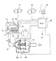
図1に、この実施の形態の内燃機関の排気ガス浄化システム1の構成を示す。この排気ガス浄化システム1は、ディーゼルエンジン10の排気マニホールド11に接続する排気通路12に連続再生型DPF装置13を設けて構成されている。この連続再生型DPF装置13は、上流側に酸化触媒13aを下流側に触媒付きフィルタ13bを有して構成される。
FIG. 1 shows the configuration of an exhaust gas purification system 1 for an internal combustion engine according to this embodiment. The exhaust gas purification system 1 is configured by providing a continuous regeneration
この酸化触媒13aは、多孔質のセラミックのハニカム構造等の担持体に、白金(Pt)等の酸化触媒を担持させて形成され、触媒付きフィルタ13bは、多孔質のセラミックのハニカムのチャンネルの入口と出口を交互に目封じしたモノリスハニカム型ウオールフロータイプのフィルタや、アルミナ等の無機繊維をランダムに積層したフェルト状のフィルタ等で形成される。このフィルタの部分に白金や酸化セリウム等の触媒を担持する。
This
そして、触媒付きフィルタ13bに、モノリスハニカム型ウオールフロータイプのフィルタを採用した場合には、排気ガスG中のPM(粒子状物質)は多孔質のセラミックの壁で捕集(トラップ)され、繊維型フィルタタイプを採用した場合には、フィルタの無機繊維でPMを捕集する。
When a monolith honeycomb wall flow type filter is adopted as the filter with
そして、触媒付きフィルタ13bのPMの堆積量を推定するために、連続再生型DPF装置13の前後に接続された導通管に差圧センサ21が設けられる。また、触媒付きフィルタ13bの再生制御用に、酸化触媒13aと触媒付きフィルタ13bの上流側、中間及び下流側に、それぞれ、酸化触媒入口排気温度センサ22、フィルタ入口排気温度センサ23が設けられる。
Then, in order to estimate the amount of PM deposited on the filter with
これらのセンサの出力値は、エンジン10の運転の全般的な制御を行うと共に、連続再生型DPF装置13の再生制御も行う制御装置(ECU:エンジンコントロールユニット)30に入力され、この制御装置30から出力される制御信号により、エンジン10の燃料噴射装置(噴射ノズル)14や、吸気マニホールド15への吸気量を調整する図示しない吸気絞り弁や、図示しないEGR通路にEGRクーラと共に設けられたEGR量を調整するEGRバルブ等が制御される。
Output values of these sensors are input to a control device (ECU: engine control unit) 30 that performs overall control of the operation of the
この燃料噴射装置14は燃料ポンプ(図示しない)で昇圧された高圧の燃料を一時的に貯えるコモンレール噴射システム(図示しない)に接続されており、制御装置30には、エンジンの運転のために、アクセルポジションセンサ(APS)31からのアクセル開度、回転数センサ32からのエンジン回転数等の情報の他、車両速度、冷却水温度等の情報も入力される。
The
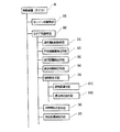
そして、本発明においては、図2に示すように、制御装置30は、エンジンの運転を制御するエンジン制御手段20Cと、排気ガス浄化システム1のためのディーゼルパティキュレートフィルタ(DPF)制御手段30C等を有して構成される。そして、このDPF制御手段30Cは、通常運転制御手段31C、PM捕集量検出手段32C、走行距離検出手段33C、再生時期判定手段34C、強制再生手段35C、手動再生警告手段36C、冷却水温検出手段37C等を有して構成される。
In the present invention, as shown in FIG. 2, the
通常運転制御手段31Cは、特に、連続再生型DPF装置13の再生に関係なしに行われる通常の運転を行うための手段であり、アクセルポジションセンサ31の信号及び回転数センサ32の信号に基づいて制御装置30で演算された通電時間信号により、所定量の燃料が燃料噴射装置14から噴射される通常の噴射制御が行われる。
The normal operation control means 31C is a means for performing a normal operation that is performed regardless of the regeneration of the continuous regeneration
PM捕集量検出手段32Cは、連続再生型DPF装置13の触媒付きフィルタ13bに捕集されるPMの捕集量を検出する手段であり、この実施の形態では、連続再生型DPF装置13の前後の差圧、即ち、差圧センサ21による測定値ΔPm を用いて検出する。
The PM collection amount detection means 32C is a means for detecting the amount of PM collected by the
走行距離検出手段33Cは、DPF再生の後に車両が走行した距離ΔMc を検出する手段であり、強制再生が行われた場合には、再生の開始時から再生終了時までの適当な時期にリセットされる。 The travel distance detection means 33C is a means for detecting the distance ΔMc traveled by the vehicle after DPF regeneration. When forced regeneration is performed, the travel distance detection means 33C is reset at an appropriate time from the start of regeneration to the end of regeneration. The
再生時期判定手段34Cは、PM捕集量検出手段32Cで検出された差圧検出値ΔPm 及び走行距離検出手段33Cにより検出された走行距離ΔMc を、それぞれ所定の判定値と比較することにより、DPFの再生開始時期を判定する手段である。
The regeneration timing determination unit 34C compares the detected differential pressure ΔPm detected by the PM trapping
強制再生手段35Cは、連続再生型DPF装置13の種類に応じて多少制御が異なるが、エンジン10の筒内(シリンダ内)噴射においてマルチ噴射(多段遅延噴射)を行って、あるいは、排気絞り制御を行なって、排気温度を酸化触媒13aの活性温度まで上昇させる排気昇温手段351Cと、その後ポスト噴射(後噴射)を行って排気ガス中に未燃燃料を添加し、この未燃燃料を酸化触媒13aで酸化させることにより、フィルタ入口排気温度センサ23で検知されるフィルタ入口排気温度を上げて、PMの酸化除去に適した温度や環境になるようにする未燃燃料添加手段352Cとを有して構成され、これらの手段により、触媒付きフィルタ13bに捕集されたPMを強制的に燃焼除去して触媒付きフィルタ13bを強制再生する。なお、排気昇温手段351Cは、マルチ噴射に加えて、排気絞り制御を併用することもあり、更には、排気昇温制御及び未燃燃料添加制御において、吸気絞り制御やEGR制御も併用する場合ある。
The forced regeneration means 35C has a slightly different control depending on the type of the continuous regeneration
手動再生警告手段36Cは、点滅灯(DPFランプ)41、警告灯(警告ランプ)42等で構成され、ドライバー(運転者)に、点滅灯41の点滅により手動による強制再生手段35Cの作動を促す警告を行ったり、警告灯42の点灯によりドライバーに車両をサービスセンターに持っていくように促す手段である。なお、この警告を受けたドライバーは手動再生スイッチ(マニュアル再生スイッチ)43を操作することにより、強制再生手段35Cを作動することができる。
The manual regeneration warning means 36C includes a blinking light (DPF lamp) 41, a warning light (warning light) 42, and the like, and urges the driver (driver) to manually activate the forced regeneration means 35C by blinking the blinking
冷却水温検出手段37Cは、エンジン10に設けられた水温センサ33等で構成され、エンジン冷却水温Tw を検出する手段である。
The cooling water
そして、これらの各種手段を有するDPF制御手段30Cは、PM捕集量検出手段32Cで検出されたDPF前後差圧ΔPm と、走行距離検出手段33Cで検出されたDPF再生の後の走行距離ΔMc に基づいて、通常運転制御手段31Cによる通常の運転を継続したり、ドライバーに対して手動による強制再生手段35Cの作動を促す警告を行ったり、自動的に強制再生手段35Cを作動させたりする手段として構成される。 Then, the DPF control means 30C having these various means sets the DPF front-rear differential pressure ΔPm detected by the PM collection amount detection means 32C and the travel distance ΔMc after the DPF regeneration detected by the travel distance detection means 33C. Based on this, the normal operation by the normal operation control means 31C is continued, a warning for prompting the driver to manually operate the forced regeneration means 35C, or the automatic regeneration means 35C is automatically operated. Composed.
次に、この排気ガス浄化システム1のDPF再生制御について説明する。この排気ガス浄化システム1の制御においては、通常運転制御手段31Cによって通常の運転が行われ、PMを捕集するが、この通常の運転において、再生時期判定手段34Cによって、再生開始が判断されると手動再生警告手段36Cによる警告又は強制再生手段35Cによる走行自動再生を行う。
Next, DPF regeneration control of the exhaust gas purification system 1 will be described. In the control of the exhaust gas purification system 1, the normal operation is performed by the normal
つまり、PM捕集量検出手段32Cで検出されたDPF前後差圧ΔPm と走行距離検出手段33Cで検出された走行距離ΔMc が、所定の範囲内に入るか否かによって、手動再生の要否、走行自動再生の要否を判断して、必要に応じて、各種の処理を行った後戻って、更に、通常運転制御手段31Cによる通常の運転を行う。そして、通常の運転と再生制御を繰り返しながら、車両の運転が行われる。 That is, whether or not manual regeneration is necessary depends on whether or not the DPF front-rear differential pressure ΔPm detected by the PM trapping amount detection means 32C and the travel distance ΔMc detected by the travel distance detection means 33C fall within a predetermined range. It is determined whether or not the automatic running regeneration is necessary, and after performing various processes as necessary, the process returns to the normal operation by the normal operation control means 31C. Then, the vehicle is driven while repeating normal driving and regeneration control.
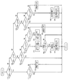
この再生制御について、図4に示す再生制御用マップを参照しながら説明する。なお、この再生制御は図5に例示するような再生制御フローにより実施できる。 This reproduction control will be described with reference to the reproduction control map shown in FIG. This regeneration control can be carried out by a regeneration control flow as exemplified in FIG.
先ず、走行距離ΔMc が第1閾値ΔM1 より小さい領域Rm1にある時は、強制再生を行うと、オイル中の燃料の蒸発が不十分であるため、オイルダイリューションの問題を回避するために再生制御の実行を禁止する。 First, when the travel distance ΔMc is in the region Rm1 smaller than the first threshold value ΔM1, if the forced regeneration is performed, the fuel in the oil is insufficiently evaporated, so that the regeneration is performed to avoid the problem of oil dilution. Prohibit execution of control.
次に、走行距離ΔMc が第1閾値ΔM1 と第2閾値ΔM2 との間の所定の範囲内Rm2にある場合には、まだ、走行が不十分でエンジンオイルに混入した燃料分の蒸発が十分に行われていないため自動強制再生は行わずに、車両を停止して手動再生スイッチ43を押して強制再生を行う手動再生(マニュアル再生)を促すために、検出されたDPF前後差圧ΔPm が、第1閾値ΔP1 を超える(マニュアル点滅1)と点滅灯(DPFランプ)41をゆっくり点滅させる。更に、検出されたDPF前後差圧ΔPm が、第1閾値ΔP1 より大きな第2閾値ΔP2 を超える(マニュアル点滅2)と点滅灯41を早く点滅させ、ドライバーに対して、車両を停止しての手動による強制再生を強く促す。
Next, when the travel distance ΔMc is within a predetermined range Rm2 between the first threshold value ΔM1 and the second threshold value ΔM2, the travel is still insufficient and the fuel component mixed in the engine oil is sufficiently evaporated. Since the automatic regeneration is not performed, the detected DPF front-rear differential pressure ΔPm is used in order to prompt manual regeneration (manual regeneration) in which the vehicle is stopped and the manual regeneration switch 43 is pressed to perform forced regeneration without performing automatic forced regeneration. When 1 threshold value ΔP1 is exceeded (manual flashing 1), the flashing lamp (DPF lamp) 41 is slowly flashed. Further, when the detected DPF front-rear differential pressure ΔPm exceeds the second threshold value ΔP2 larger than the first threshold value ΔP1 (manual flashing 2), the flashing
そして、走行距離ΔMc が第2閾値ΔM2 と第3閾値ΔM3 との間の所定の範囲内Rm3にある場合には、エンジンオイルに混入した燃料分の蒸発が十分に行われ、走行中の自動強制再生(走行自動再生)が可能になっているので、検出されたDPF前後差圧ΔPm が、第1閾値ΔP1 を超える(走行自動再生1)と、自動的に強制再生制御を行う。この走行自動再生により、ドライバーに手動による強制再生、即ち、手動再生スイッチ43のON/OFF操作に関する負担を少なくする。 When the travel distance ΔMc is within a predetermined range Rm3 between the second threshold value ΔM2 and the third threshold value ΔM3, the fuel mixed in the engine oil is sufficiently evaporated, and the automatic forcing during traveling is performed. Since regeneration (travel automatic regeneration) is possible, forced regeneration control is automatically performed when the detected differential pressure ΔPm across the DPF exceeds the first threshold value ΔP1 (travel automatic regeneration 1). This automatic driving regeneration reduces the burden on the driver for manual regeneration, that is, on / off operation of the manual regeneration switch 43.
更に、検出されたDPF前後差圧ΔPm に関係なく、走行距離ΔMc が第3閾値ΔM3 を超えた所定の範囲内Rm4にある場合(走行自動再生2)には、触媒付きフィルタ13bにおけるPMの偏積に起因する熱暴走及びDPFの溶損を防止するために、自動的に強制再生制御を行う。
Further, when the travel distance ΔMc is within a predetermined range Rm4 exceeding the third threshold value ΔM3 regardless of the detected DPF front-rear differential pressure ΔPm (travel automatic regeneration 2), the PM deviation in the catalyst-equipped
なお、走行距離ΔMc に関係せずに、検出されたDPF前後差圧ΔPm が第3閾値ΔP3 を超える(Rp4:警告灯点滅)と、急激なPMの燃焼である熱暴走を回避するために、手動再生及び走行自動再生を禁止した状態にすると共に、ドライバーにサービスセンターに持っていくことを促すための警告灯42を点灯する。
In order to avoid thermal runaway that is rapid combustion of PM when the detected differential pressure ΔPm before and after DPF exceeds the third threshold value ΔP3 (Rp4: warning light blinking) regardless of the travel distance ΔMc, While the manual regeneration and the automatic traveling regeneration are prohibited, a
従って、このDPF制御手段30Cは、停車アイドル状態で再生制御を行なうように警告されたドライバーが手動再生スイッチ43を押した場合に触媒付きフィルタ13bの強制再生制御を行なう手動再生モードと、車両走行中に自動的に触媒付きフィルタ13bの強制再生制御を行なう走行自動再生モードを有して構成されることになる。
Accordingly, the DPF control means 30C includes a manual regeneration mode in which forced regeneration control of the filter with
そして、本発明においては、図5に示すステップS27の手動再生やステップS33の走行自動再生によって、強制再生手段35Cにより、DPF装置13の強制再生を行なう場合に、ドライバーのエンジントラブルとの誤解を招くエンジン冷却水温度の異常な上昇を防止するために、以下のように、DPF制御手段30Cが構成される。
In the present invention, when the forced regeneration means 35C forcibly regenerates the
このDPF制御手段30Cは、排気昇温手段351Cを用いた触媒付きフィルタ13bの強制再生制御中に、冷却水温検出手段37Cによって検出されたエンジン冷却水温Tw が所定の判定用水温Tw1,Tw2を超えた場合には、排気昇温手段351Cの作動を中止する制御を行ない、更に、ポスト噴射等による未燃燃料添加制御を行なっている場合には、これを行なう未燃燃料添加手段352Cの作動も中止するように構成される。
In the DPF control means 30C, the engine cooling water temperature Tw detected by the cooling water temperature detection means 37C exceeds the predetermined determination water temperatures Tw1 and Tw2 during the forced regeneration control of the
そして、この排気昇温手段351Cの作動を中止するための判定用水温Tw1,Tw2においては、手動再生モードにおける所定の第1判定用水温Tw1は、走行自動再生モードにおける所定の第2判定用水温Tw2よりも大きく設定される。 In the determination water temperatures Tw1 and Tw2 for stopping the operation of the exhaust gas temperature raising means 351C, the predetermined first determination water temperature Tw1 in the manual regeneration mode is the predetermined second determination water temperature in the traveling automatic regeneration mode. It is set larger than Tw2.
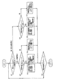
そして、上記のエンジン冷却水温Tw と関係する強制再生制御は、図3に示すような制御フローによって実施できる。この図3の制御フローは、図5のステップS27の手動再生やステップS33の走行自動再生によって、強制再生手段35Cにより、DPF装置13の強制再生を行なう場合に、呼ばれる制御フローとして示してある。
Then, the forced regeneration control related to the engine cooling water temperature Tw can be performed by a control flow as shown in FIG. The control flow of FIG. 3 is shown as a control flow called when the forced regeneration means 35C performs forced regeneration of the
この制御フローが呼ばれてスタートすると、ステップS11で再生モードのチェックを行い、手動再生か走行自動再生かを判定する。この判定で手動再生であると判定された場合には、ステップS12でエンジン冷却水温Tw のチェックを行う。つまり、エンジン冷却水温Tw が所定の第1判定用水温Tw1よりも小さい時はステップS13で強制再生手段35Cを作動し、大きい時は、ステップS14でこの強制再生手段35Cの作動を中止する。 When this control flow is called and started, the regeneration mode is checked in step S11 to determine whether it is manual regeneration or traveling automatic regeneration. If it is determined in this determination that the regeneration is manual, the engine coolant temperature Tw is checked in step S12. That is, when the engine coolant temperature Tw is lower than the predetermined first determination water temperature Tw1, the forced regeneration means 35C is operated at step S13, and when it is larger, the operation of the forced regeneration means 35C is stopped at step S14.
このステップS13の手動再生による強制再生制御では、詳細な制御フローは省略するが、排気温度が所定の判定用排気温度より低い場合は第1段階のマルチ噴射による排気昇温制御のみを行い、排気温度が所定の判定用排気温度を超えた場合は第2段階に移行し、さらなる昇温制御、ここでは、マルチ噴射による排気昇温制御に加えポスト噴射による未燃燃料添加制御を行う。そして、この強制再生制御を、再生モードのチェックのインターバルやエンジン冷却水温Tw のチェックのインターバルに関係する所定の制御時間Δtcの間行い、ステップS18に行く。 In the forced regeneration control by manual regeneration in step S13, a detailed control flow is omitted, but when the exhaust temperature is lower than a predetermined exhaust temperature for determination, only exhaust temperature increase control by multi-injection in the first stage is performed, When the temperature exceeds a predetermined exhaust temperature for determination, the process proceeds to the second stage, where further temperature increase control, here, exhaust temperature increase control by multi-injection and unburned fuel addition control by post injection are performed. Then, this forced regeneration control is performed for a predetermined control time Δtc related to the regeneration mode check interval and the engine coolant temperature Tw check interval, and the process goes to step S18.
また、ステップS12で、エンジン冷却水温Tw が所定の第1判定用水温Tw1以上である場合には、ステップS14に行き、マルチ噴射及びポスト噴射等の強制再生制御を中止し、所定の制御時間Δtcを経過したらステップS18に行く。 In step S12, if the engine coolant temperature Tw is equal to or higher than the predetermined first determination water temperature Tw1, the process goes to step S14 to stop the forced regeneration control such as multi-injection and post-injection, and the predetermined control time Δtc. When elapses, go to step S18.
ステップS11の再生モードのチェックで、走行自動再生モードであると判定された場合には、ステップS15でエンジン冷却水温Tw のチェックを行う。つまり、このエンジン冷却水温Tw が所定の第2判定用水温Tw2よりも小さい時はステップS16で走行自動再生による強制再生手段35Cを作動し、大きい時は、ステップS17でこの強制再生手段35Cの作動を中止する。なお、走行時には冷却水温Tw が上昇し易いので、走行自動再生における所定の第2判定用水温Tw2を、手動再生モードにおける所定の第1判定用水温Tw1よりも小さく設定すると、より適切な再生制御が行なわれるようになる。 If it is determined in the regeneration mode check in step S11 that the traveling automatic regeneration mode is selected, the engine coolant temperature Tw is checked in step S15. That is, when the engine cooling water temperature Tw is lower than the predetermined second determination water temperature Tw2, the forced regeneration means 35C by automatic running regeneration is activated in step S16, and when it is larger, the forced regeneration means 35C is activated in step S17. Cancel. Since the cooling water temperature Tw is likely to rise during traveling, more appropriate regeneration control can be achieved if the predetermined second determination water temperature Tw2 in the automatic regeneration is set smaller than the predetermined first determination water temperature Tw1 in the manual regeneration mode. Will be performed.
このステップS16の走行自動再生による強制再生制御では、詳細な制御フローは省略するが、排気温度が所定の判定用排気温度より低い場合は第1段階のマルチ噴射による排気昇温制御のみを行い、排気温度が所定の判定用排気温度を超えた場合は第2段階のマルチ噴射による排気昇温制御とポスト噴射による未燃燃料添加制御を行う。そして、これらの走行自動再生による強制再生制御を、再生モードのチェックのインターバルやエンジン冷却水温のチェックのインターバルに関係する所定の制御時間Δtcの間行い、ステップS18に行く。 In the forced regeneration control by the automatic running regeneration in step S16, a detailed control flow is omitted, but when the exhaust gas temperature is lower than a predetermined determination exhaust gas temperature, only the exhaust gas temperature raising control by the first stage multi-injection is performed. When the exhaust temperature exceeds a predetermined exhaust temperature for determination, exhaust temperature increase control by multi-injection in the second stage and unburned fuel addition control by post injection are performed. Then, the forced regeneration control by the automatic traveling regeneration is performed for a predetermined control time Δtc related to the regeneration mode check interval and the engine coolant temperature check interval, and the process goes to step S18.
また、ステップS15で、エンジン冷却水温Tw が所定の第2判定用水温Tw2以上である場合には、ステップS17に行き、マルチ噴射及びポスト噴射等の強制再生制御を中止し、所定の制御時間Δtcを経過したらステップS18に行く。 If the engine coolant temperature Tw is equal to or higher than the predetermined second determination water temperature Tw2 in step S15, the process goes to step S17 to stop the forced regeneration control such as multi-injection and post-injection, and the predetermined control time Δtc. When elapses, go to step S18.
ステップS18では、再生制御が完了したか否かをチェックする。このチェックは、DPF前後差圧ΔPm が所定の完了判定用差圧より小さくなったか否かでおこなったり、強制再生制御の実行累積時間が所定の完了判定用時間を経過したか否かで行なったりする。このステップS18で再生制御が完了していないと判定された場合には、ステップS11に戻り、ステップS11〜ステップS18を繰り返す。また、このステップS18で再生制御が完了していると判定された場合には、再生制御を終了し、リターンする。 In step S18, it is checked whether or not the reproduction control is completed. This check is performed based on whether the DPF front-rear differential pressure ΔPm is smaller than a predetermined completion determination differential pressure, or whether the forced regeneration control execution cumulative time has passed a predetermined completion determination time. To do. If it is determined in step S18 that the regeneration control has not been completed, the process returns to step S11, and steps S11 to S18 are repeated. If it is determined in step S18 that the regeneration control has been completed, the regeneration control is terminated and the process returns.
この図3の制御フローにより、排気昇温手段351Cを用いた触媒付きフィルタ13bの強制再生制御中に、冷却水温検出手段37Cによって検出されたエンジン冷却水温Tw が所定の判定用水温Tw1,Tw2を超えた場合には、排気昇温手段351Cの作動を中止することができる。更に、未燃燃料添加手段352Cが作動している場合には、排気昇温手段351Cの作動を中止すると共に、未燃燃料添加手段352Cの作動も中止することができる。
According to the control flow of FIG. 3, the engine cooling water temperature Tw detected by the cooling water temperature detecting means 37C during the forced regeneration control of the catalyst-equipped
従って、連続再生型DPF装置13の触媒付きフィルタ13bの強制再生中にエンジン冷却水温Tw が上昇して、運転席の水温メーターが異常に上がることを防止でき、これにより、強制再生中に、水温メーターを見ているドライバーにエンジントラブル発生との誤解を与えることを回避できる
なお、上記の説明では、排気ガス浄化システムにおけるDPF装置として、フィルタに触媒を担持させると共に該フィルタの上流側に酸化触媒を設けた装置を例にして説明したが、本発明はこれに限定されるものではなく、触媒を担持しないフィルタのDPF装置、フィルタに酸化触媒を担持させた連続再生型DPF装置、フィルタの上流側に酸化触媒を設けた連続再生型DPF装置等の他のタイプのDPFにも適用可能である。
Therefore, it is possible to prevent the engine cooling water temperature Tw from rising during forced regeneration of the catalyst-equipped
1 排気ガス浄化システム
10 ディーゼルエンジン
13 連続再生型DPF装置
13a 酸化触媒
13b 触媒付きフィルタ
30 制御装置(ECU)
30C DPF制御手段
31C 通常運転制御手段
32C PM捕集量検出手段
33C 走行距離検出手段
34C 再生時期判定手段
35C 強制再生手段
351C 排気昇温手段
352C 未燃燃料添加手段
36C 手動再生警告手段
37C 冷却水温検出手段
Tw エンジン冷却水温
Tw1 所定の第1判定用水温
Tw2 所定の第2判定用水温
DESCRIPTION OF SYMBOLS 1 Exhaust
30C DPF control means 31C Normal operation control means 32C PM collection amount detection means 33C Travel distance detection means 34C Regeneration time determination means 35C Forced regeneration means 351C Exhaust temperature raising means 352C Unburned fuel addition means 36C Manual regeneration warning means
37C Cooling water temperature detection means TW Engine cooling water temperature
Tw1 Predetermined first determination water temperature Tw2 Predetermined second determination water temperature
Claims (7)
前記排気昇温手段を用いたフィルタの強制再生制御中に、前記冷却水温検出手段によって検出されたエンジン冷却水温が所定の判定用水温を超えた場合には、前記排気昇温手段の作動を中止することを特徴とする排気ガス浄化システムの制御方法。 A diesel particulate filter device is provided in an exhaust gas passage of an internal combustion engine mounted on a vehicle, a regeneration timing determining means for determining a regeneration timing of the filter of the diesel particulate filter device, and an exhaust temperature raising for raising the temperature of the exhaust gas And when the exhaust gas temperature is low and the exhaust gas temperature is low, the exhaust gas temperature is raised by the exhaust gas temperature raising means. In the exhaust gas purification system provided with diesel particulate filter control means for performing forced regeneration control to regenerate the filter,
During forced regeneration control of the filter using the exhaust temperature raising means, if the engine cooling water temperature detected by the cooling water temperature detecting means exceeds a predetermined water temperature for determination, the operation of the exhaust temperature raising means is stopped. A control method for an exhaust gas purification system.
前記ディーゼルパティキュレートフィルタ制御手段が、前記排気昇温手段を用いたフィルタの強制再生制御中に、前記冷却水温検出手段によって検出されたエンジン冷却水温が所定の判定用水温を超えた場合には、前記排気昇温手段の作動を中止する制御を行なうように構成されることを特徴とする排気ガス浄化システム。 A diesel particulate filter device is provided in an exhaust gas passage of an internal combustion engine mounted on a vehicle, a regeneration timing determining means for determining a regeneration timing of the filter of the diesel particulate filter device, and an exhaust temperature raising for raising the temperature of the exhaust gas And when the exhaust gas temperature is low and the exhaust gas temperature is low, the exhaust gas temperature is raised by the exhaust gas temperature raising means. In the exhaust gas purification system provided with diesel particulate filter control means for performing forced regeneration control to regenerate the filter,
When the engine coolant temperature detected by the cooling water temperature detection means exceeds a predetermined determination water temperature during the forced regeneration control of the filter using the exhaust gas temperature raising means, the diesel particulate filter control means, An exhaust gas purification system configured to perform control to stop the operation of the exhaust gas temperature raising means.
The diesel particulate filter device is a diesel particulate filter device formed by a filter without supporting a catalyst, a continuous regeneration type diesel particulate filter device having an oxidation catalyst supported on the filter, and an oxidation catalyst upstream of the filter. The continuous regeneration type diesel particulate filter device provided is any one of the continuous regeneration type diesel particulate filter device in which the catalyst is supported on the filter and the oxidation catalyst is provided on the upstream side of the filter, or a combination thereof. The exhaust gas purification system according to claim 5 or 6.
Priority Applications (4)
| Application Number | Priority Date | Filing Date | Title |
|---|---|---|---|
| JP2004113375A JP4161931B2 (en) | 2004-04-07 | 2004-04-07 | Exhaust gas purification system control method and exhaust gas purification system |
| US11/082,832 US7168244B2 (en) | 2004-04-07 | 2005-03-18 | Control method for an exhaust gas purification system and an exhaust gas purification system |
| EP05102139.2A EP1584807B1 (en) | 2004-04-07 | 2005-03-18 | Control method for an exhaust gas purification system and an exhaust gas purification system |
| CNB2005100600853A CN100549372C (en) | 2004-04-07 | 2005-03-31 | The controlling method of waste gas cleaning system and waste gas cleaning system |
Applications Claiming Priority (1)
| Application Number | Priority Date | Filing Date | Title |
|---|---|---|---|
| JP2004113375A JP4161931B2 (en) | 2004-04-07 | 2004-04-07 | Exhaust gas purification system control method and exhaust gas purification system |
Publications (2)
| Publication Number | Publication Date |
|---|---|
| JP2005299418A true JP2005299418A (en) | 2005-10-27 |
| JP4161931B2 JP4161931B2 (en) | 2008-10-08 |
Family
ID=34909509
Family Applications (1)
| Application Number | Title | Priority Date | Filing Date |
|---|---|---|---|
| JP2004113375A Expired - Fee Related JP4161931B2 (en) | 2004-04-07 | 2004-04-07 | Exhaust gas purification system control method and exhaust gas purification system |
Country Status (4)
| Country | Link |
|---|---|
| US (1) | US7168244B2 (en) |
| EP (1) | EP1584807B1 (en) |
| JP (1) | JP4161931B2 (en) |
| CN (1) | CN100549372C (en) |
Cited By (5)
| Publication number | Priority date | Publication date | Assignee | Title |
|---|---|---|---|---|
| WO2007088715A1 (en) * | 2006-02-01 | 2007-08-09 | Isuzu Motors Limited | Method for controlling exhaust gas purification system, and exhaust gas purification system |
| WO2008129781A1 (en) * | 2007-04-17 | 2008-10-30 | Hino Motors, Ltd. | Exhaust purification apparatus |
| JP2011226356A (en) * | 2010-04-19 | 2011-11-10 | Volvo Powertrain Ab | Exhaust emission control device of diesel engine |
| JP2012012997A (en) * | 2010-06-30 | 2012-01-19 | Mazda Motor Corp | diesel engine |
| JP2017095927A (en) * | 2015-11-20 | 2017-06-01 | コベルコ建機株式会社 | Construction machine |
Families Citing this family (22)
| Publication number | Priority date | Publication date | Assignee | Title |
|---|---|---|---|---|
| JP3824003B2 (en) * | 2005-02-24 | 2006-09-20 | いすゞ自動車株式会社 | Exhaust gas purification system |
| JP4483832B2 (en) * | 2006-06-16 | 2010-06-16 | トヨタ自動車株式会社 | PM trapper failure detection system |
| SE0700235L (en) | 2007-01-31 | 2008-08-01 | Scania Cv Ab | Method and system for testing a vehicle exhaust system |
| JP4100451B1 (en) * | 2007-03-02 | 2008-06-11 | いすゞ自動車株式会社 | Exhaust gas purification method and exhaust gas purification system |
| US8316638B2 (en) * | 2007-12-12 | 2012-11-27 | GM Global Technology Operations LLC | Control system for a particulate matter filter |
| US8322132B2 (en) | 2008-04-30 | 2012-12-04 | Perkins Engines Company Limited | Exhaust treatment system implementing regeneration control |
| JP4962622B2 (en) * | 2008-12-24 | 2012-06-27 | トヨタ自動車株式会社 | Vehicle control device |
| US8061129B2 (en) * | 2009-01-30 | 2011-11-22 | Thermo King Corporation and Donaldson Company, Inc. | System and method to regenerate a diesel particulate filter |
| US8350682B2 (en) * | 2009-06-12 | 2013-01-08 | Mack Trucks, Inc. | DPF warning system |
| JP5325090B2 (en) * | 2009-12-25 | 2013-10-23 | 三菱重工業株式会社 | Exhaust gas purification device for internal combustion engine |
| US8347612B2 (en) * | 2010-03-19 | 2013-01-08 | GM Global Technology Operations LLC | Method and apparatus for regenerating a particulate filter system |
| WO2011136184A1 (en) * | 2010-04-30 | 2011-11-03 | ヤンマー株式会社 | Exhaust gas cleaning system for engine-driven machines |
| JP5533260B2 (en) * | 2010-05-25 | 2014-06-25 | いすゞ自動車株式会社 | DPF system |
| KR101251517B1 (en) * | 2010-12-09 | 2013-04-05 | 현대자동차주식회사 | Exhaust gas post processing system |
| JP5864901B2 (en) * | 2011-05-19 | 2016-02-17 | 日野自動車株式会社 | Manual regeneration of particulate filter |
| US9534551B2 (en) * | 2011-09-27 | 2017-01-03 | Kubota Corporation | Working machine |
| JP6011224B2 (en) * | 2012-10-09 | 2016-10-19 | いすゞ自動車株式会社 | Exhaust gas purification system and exhaust gas purification method |
| EP2930323B1 (en) * | 2012-12-07 | 2017-03-29 | Toyota Jidosha Kabushiki Kaisha | Abnormality detection device for exhaust gas purification apparatus |
| DE102013222022A1 (en) * | 2013-10-30 | 2015-04-30 | Robert Bosch Gmbh | Method and device for detecting a water passage by means of distance sensors |
| CN106640304A (en) * | 2017-01-25 | 2017-05-10 | 中国第汽车股份有限公司 | Regeneration method of particle collection system of diesel engine |
| CN109838296B (en) * | 2017-11-29 | 2021-09-28 | 上海汽车集团股份有限公司 | Particulate filter regeneration management method and system with driver guidance function |
| CN115013129B (en) * | 2022-06-16 | 2023-08-08 | 江铃汽车股份有限公司 | Control strategy for preventing PN (Positive and negative) emissions of tail gas of diesel engine from exceeding standard |
Family Cites Families (13)
| Publication number | Priority date | Publication date | Assignee | Title |
|---|---|---|---|---|
| DE3580606D1 (en) * | 1984-03-31 | 1991-01-03 | Mitsubishi Motors Corp | REGENERATION SYSTEM FOR A DIESEL PARTICLE OXYDING DEVICE. |
| US5121601A (en) * | 1986-10-21 | 1992-06-16 | Kammel Refaat A | Diesel engine exhaust oxidizer |
| GB2239407B (en) * | 1989-12-27 | 1994-10-12 | Nissan Motor | Exhaust gas purifying device for an internal combustion engine |
| DE69625823T2 (en) * | 1995-10-30 | 2003-09-04 | Toyota Jidosha K.K., Toyota | EXHAUST CONTROL DEVICE FOR INTERNAL COMBUSTION ENGINE |
| DE50000400D1 (en) * | 2000-11-03 | 2002-09-26 | Ford Global Tech Inc | Control arrangement and method for interrupting the regeneration of a particle filter of a diesel engine |
| KR20030022043A (en) * | 2001-09-07 | 2003-03-15 | 미쓰비시 지도샤 고교(주) | Exhaust emission control device for engine |
| JP4042399B2 (en) * | 2001-12-12 | 2008-02-06 | 三菱自動車工業株式会社 | Exhaust purification device |
| JP4165082B2 (en) | 2002-02-13 | 2008-10-15 | 日産自動車株式会社 | Exhaust purification device |
| JP3870815B2 (en) * | 2002-03-29 | 2007-01-24 | 日産自動車株式会社 | Exhaust gas purification device for internal combustion engine |
| JP4007085B2 (en) | 2002-06-13 | 2007-11-14 | 株式会社デンソー | Exhaust gas purification device for internal combustion engine |
| JP3823923B2 (en) * | 2003-01-16 | 2006-09-20 | 日産自動車株式会社 | Exhaust purification device |
| JP3846452B2 (en) * | 2003-05-20 | 2006-11-15 | マツダ株式会社 | Engine control device |
| JP4333289B2 (en) * | 2003-09-03 | 2009-09-16 | いすゞ自動車株式会社 | Exhaust gas purification system |
-
2004
- 2004-04-07 JP JP2004113375A patent/JP4161931B2/en not_active Expired - Fee Related
-
2005
- 2005-03-18 EP EP05102139.2A patent/EP1584807B1/en not_active Ceased
- 2005-03-18 US US11/082,832 patent/US7168244B2/en not_active Expired - Lifetime
- 2005-03-31 CN CNB2005100600853A patent/CN100549372C/en not_active Expired - Fee Related
Cited By (9)
| Publication number | Priority date | Publication date | Assignee | Title |
|---|---|---|---|---|
| WO2007088715A1 (en) * | 2006-02-01 | 2007-08-09 | Isuzu Motors Limited | Method for controlling exhaust gas purification system, and exhaust gas purification system |
| US7992383B2 (en) | 2006-02-01 | 2011-08-09 | Isuzu Motors Limited | Method for controlling exhaust gas purification system and exhaust gas purification system |
| WO2008129781A1 (en) * | 2007-04-17 | 2008-10-30 | Hino Motors, Ltd. | Exhaust purification apparatus |
| JP2008267199A (en) * | 2007-04-17 | 2008-11-06 | Hino Motors Ltd | Exhaust purification device |
| US8327626B2 (en) | 2007-04-17 | 2012-12-11 | Hino Motors, Ltd. | Exhaust emission control device |
| JP2011226356A (en) * | 2010-04-19 | 2011-11-10 | Volvo Powertrain Ab | Exhaust emission control device of diesel engine |
| JP2012012997A (en) * | 2010-06-30 | 2012-01-19 | Mazda Motor Corp | diesel engine |
| JP2017095927A (en) * | 2015-11-20 | 2017-06-01 | コベルコ建機株式会社 | Construction machine |
| US10161330B2 (en) | 2015-11-20 | 2018-12-25 | Kobelco Construction Machinery Co., Ltd. | Construction machine |
Also Published As
| Publication number | Publication date |
|---|---|
| EP1584807B1 (en) | 2013-05-08 |
| US7168244B2 (en) | 2007-01-30 |
| JP4161931B2 (en) | 2008-10-08 |
| CN1680686A (en) | 2005-10-12 |
| EP1584807A2 (en) | 2005-10-12 |
| CN100549372C (en) | 2009-10-14 |
| US20060000201A1 (en) | 2006-01-05 |
| EP1584807A3 (en) | 2007-05-09 |
Similar Documents
| Publication | Publication Date | Title |
|---|---|---|
| JP4161931B2 (en) | Exhaust gas purification system control method and exhaust gas purification system | |
| JP4175281B2 (en) | Exhaust gas purification system control method and exhaust gas purification system | |
| JP4161932B2 (en) | Exhaust gas purification system control method and exhaust gas purification system | |
| CN101379274B (en) | Control method of exhaust gas purification system and exhaust gas purification system | |
| CN101627189B (en) | Exhaust emission purification method and exhaust emission purification system | |
| JP3933172B2 (en) | Exhaust gas purification system control method and exhaust gas purification system | |
| JP4161930B2 (en) | Exhaust gas purification system control method and exhaust gas purification system | |
| CN101379284B (en) | Method for controlling exhaust gas purification system, and exhaust gas purification system | |
| JP4169076B2 (en) | Exhaust gas purification system control method and exhaust gas purification system | |
| CN101375026B (en) | Exhaust gas purification method and exhaust gas purification system | |
| JP3988776B2 (en) | Exhaust gas purification system control method and exhaust gas purification system | |
| JP3979437B1 (en) | Exhaust gas purification system control method and exhaust gas purification system | |
| EP1942263B1 (en) | Control method of exhaust gas purification system and exhaust gas purification system | |
| JP4466158B2 (en) | Exhaust gas purification system control method and exhaust gas purification system | |
| JP4517682B2 (en) | Exhaust gas purification system | |
| JP4352946B2 (en) | Exhaust gas purification system | |
| JP2005282479A (en) | Exhaust gas purification system control method and exhaust gas purification system | |
| JP4438485B2 (en) | Exhaust gas purification system control method and exhaust gas purification system | |
| JP2007023876A (en) | Exhaust gas purification system control method and exhaust gas purification system |
Legal Events
| Date | Code | Title | Description |
|---|---|---|---|
| A977 | Report on retrieval |
Free format text: JAPANESE INTERMEDIATE CODE: A971007 Effective date: 20080214 |
|
| A131 | Notification of reasons for refusal |
Free format text: JAPANESE INTERMEDIATE CODE: A131 Effective date: 20080311 |
|
| A521 | Request for written amendment filed |
Free format text: JAPANESE INTERMEDIATE CODE: A523 Effective date: 20080507 |
|
| TRDD | Decision of grant or rejection written | ||
| A01 | Written decision to grant a patent or to grant a registration (utility model) |
Free format text: JAPANESE INTERMEDIATE CODE: A01 Effective date: 20080701 |
|
| A01 | Written decision to grant a patent or to grant a registration (utility model) |
Free format text: JAPANESE INTERMEDIATE CODE: A01 |
|
| A61 | First payment of annual fees (during grant procedure) |
Free format text: JAPANESE INTERMEDIATE CODE: A61 Effective date: 20080714 |
|
| FPAY | Renewal fee payment (event date is renewal date of database) |
Free format text: PAYMENT UNTIL: 20110801 Year of fee payment: 3 |
|
| R150 | Certificate of patent or registration of utility model |
Free format text: JAPANESE INTERMEDIATE CODE: R150 Ref document number: 4161931 Country of ref document: JP Free format text: JAPANESE INTERMEDIATE CODE: R150 |
|
| FPAY | Renewal fee payment (event date is renewal date of database) |
Free format text: PAYMENT UNTIL: 20110801 Year of fee payment: 3 |
|
| FPAY | Renewal fee payment (event date is renewal date of database) |
Free format text: PAYMENT UNTIL: 20120801 Year of fee payment: 4 |
|
| FPAY | Renewal fee payment (event date is renewal date of database) |
Free format text: PAYMENT UNTIL: 20120801 Year of fee payment: 4 |
|
| FPAY | Renewal fee payment (event date is renewal date of database) |
Free format text: PAYMENT UNTIL: 20130801 Year of fee payment: 5 |
|
| LAPS | Cancellation because of no payment of annual fees |