JP2005299401A - Fuel injection control device for internal combustion engine - Google Patents
Fuel injection control device for internal combustion engine Download PDFInfo
- Publication number
- JP2005299401A JP2005299401A JP2004112241A JP2004112241A JP2005299401A JP 2005299401 A JP2005299401 A JP 2005299401A JP 2004112241 A JP2004112241 A JP 2004112241A JP 2004112241 A JP2004112241 A JP 2004112241A JP 2005299401 A JP2005299401 A JP 2005299401A
- Authority
- JP
- Japan
- Prior art keywords
- fuel
- injector
- air
- intake port
- cylinder
- Prior art date
- Legal status (The legal status is an assumption and is not a legal conclusion. Google has not performed a legal analysis and makes no representation as to the accuracy of the status listed.)
- Pending
Links
Images


Classifications
-
- F—MECHANICAL ENGINEERING; LIGHTING; HEATING; WEAPONS; BLASTING
- F02—COMBUSTION ENGINES; HOT-GAS OR COMBUSTION-PRODUCT ENGINE PLANTS
- F02D—CONTROLLING COMBUSTION ENGINES
- F02D41/00—Electrical control of supply of combustible mixture or its constituents
- F02D41/02—Circuit arrangements for generating control signals
- F02D41/14—Introducing closed-loop corrections
- F02D41/1438—Introducing closed-loop corrections using means for determining characteristics of the combustion gases; Sensors therefor
- F02D41/1477—Introducing closed-loop corrections using means for determining characteristics of the combustion gases; Sensors therefor characterised by the regulation circuit or part of it,(e.g. comparator, PI regulator, output)
-
- F—MECHANICAL ENGINEERING; LIGHTING; HEATING; WEAPONS; BLASTING
- F02—COMBUSTION ENGINES; HOT-GAS OR COMBUSTION-PRODUCT ENGINE PLANTS
- F02D—CONTROLLING COMBUSTION ENGINES
- F02D41/00—Electrical control of supply of combustible mixture or its constituents
- F02D41/30—Controlling fuel injection
- F02D41/3094—Controlling fuel injection the fuel injection being effected by at least two different injectors, e.g. one in the intake manifold and one in the cylinder
Landscapes
- Engineering & Computer Science (AREA)
- Chemical & Material Sciences (AREA)
- Combustion & Propulsion (AREA)
- Mechanical Engineering (AREA)
- General Engineering & Computer Science (AREA)
- Electrical Control Of Air Or Fuel Supplied To Internal-Combustion Engine (AREA)
- Combined Controls Of Internal Combustion Engines (AREA)
Abstract
【課題】 空燃比のフィードバック補正制御を行なうに際し、空燃比制御性を良好にすると共に、エミッションや応答性および燃費の悪化を生じさせることのない内燃機関の燃料噴射制御装置を提供する。
【解決手段】 筒内噴射用インジェクタ11と吸気ポート噴射用インジェクタ12とを備え、運転状態に応じてそれぞれのインジェクタから適度な分担率で燃料を噴射するようにした内燃機関において、空燃比フィードバック補正の反映比率を、所定の運転条件に対応させて、筒内噴射用インジェクタと吸気ポート噴射用インジェクタとで異ならせて制御する。例えば、所定の運転条件は加速時であり、空燃比フィードバック補正の反映比率が、吸気ポート噴射用インジェクタ12の方が筒内噴射用インジェクタ11に対するのよりも大きくされている。
【選択図】 図1
PROBLEM TO BE SOLVED: To provide a fuel injection control device for an internal combustion engine which improves air-fuel ratio controllability and does not cause deterioration of emission, responsiveness and fuel consumption when performing feedback correction control of air-fuel ratio.
In an internal combustion engine that includes an in-cylinder injector 11 and an intake port injector 12, and injects fuel from each injector at an appropriate share rate according to an operating state, air-fuel ratio feedback correction The reflection ratio is controlled differently between the in-cylinder injector and the intake port injector according to a predetermined operating condition. For example, the predetermined operating condition is at the time of acceleration, and the reflection ratio of the air-fuel ratio feedback correction is made larger for the intake port injector 12 than for the in-cylinder injector 11.
[Selection] Figure 1
Description
本発明は、内燃機関の燃料噴射制御装置に関し、より詳しくは、筒内に向けて燃料を噴射する筒内噴射用インジェクタと吸気通路または吸気ポート内に向けて燃料を噴射する吸気ポート噴射用インジェクタとを備える、いわゆるデュアル噴射型内燃機関の燃料噴射制御装置に関する。 The present invention relates to a fuel injection control device for an internal combustion engine, and more specifically, an in-cylinder injector that injects fuel into a cylinder and an intake port injection injector that injects fuel into an intake passage or an intake port. And a so-called dual injection internal combustion engine fuel injection control device.
従来から、筒内に向けて燃料を噴射するための筒内噴射用インジェクタと吸気通路または吸気ポート内に向けて燃料を噴射するための吸気ポート噴射用インジェクタとを備え、機関の運転状態に応じてこれらのインジェクタを切替え使用することにより、例えば低負荷運転領域での成層燃焼と高負荷運転領域での均質燃焼を実現させたり、両者をそれらの燃料噴射分担率を変えつつ同時に使用して均質リーン燃焼や均質ストイキ燃焼を実現させて、燃費特性や出力特性の改善を図った、いわゆるデュアル噴射型内燃機関が特許文献1等により知られている。
Conventionally, it has been provided with an in-cylinder injector for injecting fuel into the cylinder and an intake port injection injector for injecting fuel into the intake passage or the intake port, depending on the operating state of the engine By switching and using these injectors, for example, stratified combustion in the low load operation region and homogeneous combustion in the high load operation region can be realized, or both can be used simultaneously while changing their fuel injection share. A so-called dual injection type internal combustion engine that realizes lean combustion and homogeneous stoichiometric combustion to improve fuel consumption characteristics and output characteristics is known from
しかしながら、かかる特許文献1に記載のものでは、排気系に空燃比センサを設け、排気中の酸素成分等からエンジンに供給される混合気の空燃比を検出することにより、空燃比のフィードバック補正制御を行なうようにしているが、それぞれのインジェクタに対する空燃比フィードバック補正の反映比率に関しては、何等考慮されていない。
However, in the one described in
ところで、筒内噴射用インジェクタと吸気ポート噴射用インジェクタとでは、その燃料が噴射される部位等が異なり、吸気ポート噴射用インジェクタの場合は、噴射された燃料の一部が吸気ポートの壁面に付着する、いわゆるポートウエットにより燃料の供給遅れが発生する可能性があるのに対し、筒内噴射用インジェクタの場合にはピストン頂面に付着する、いわゆるピストンウエットの可能性はあるが、機関暖機後での影響は僅かであり、供給遅れの問題は生じない。従って、分担率に対応させて一律に空燃比フィードバック補正を反映させても空燃比の制御感度は両者同じではなく、過渡時等においてはかえって空燃比の乱れが生じ、エミッションや応答性および燃費の悪化を招く恐れがある。 By the way, in-cylinder injectors and intake port injectors are different in the part where the fuel is injected. In the case of intake port injectors, a part of the injected fuel adheres to the wall surface of the intake port. In the case of an in-cylinder injector, there is a possibility of a so-called piston wet adhering to the piston top surface. Later effects are minor and supply delay problems do not occur. Therefore, even if the air-fuel ratio feedback correction is uniformly reflected in accordance with the sharing ratio, the air-fuel ratio control sensitivity is not the same, and in the transient state, the air-fuel ratio is disturbed. May cause deterioration.
そこで、本発明の目的は、空燃比のフィードバック補正制御を行なうに際し、空燃比制御性を良好にすると共に、エミッションや応答性および燃費の悪化を生じさせることのない内燃機関の燃料噴射制御装置を提供することにある。 Therefore, an object of the present invention is to provide a fuel injection control device for an internal combustion engine that improves air-fuel ratio controllability and does not cause deterioration of emission, responsiveness, and fuel consumption when performing feedback correction control of air-fuel ratio. It is to provide.
上記目的を達成する本発明の一形態に係る内燃機関の燃料噴射制御装置は、筒内噴射用インジェクタと吸気ポート噴射用インジェクタとを備え、運転状態に応じてそれぞれのインジェクタから適度な分担率で燃料を噴射するようにした内燃機関において、空燃比フィードバック補正の反映比率を、所定の運転条件に対応させて、筒内噴射用インジェクタと吸気ポート噴射用インジェクタとで異ならせて制御することを特徴とする。 A fuel injection control device for an internal combustion engine according to an embodiment of the present invention that achieves the above object includes an in-cylinder injector and an intake port injector, and each of the injectors has an appropriate share rate according to the operating state. In an internal combustion engine that injects fuel, the reflection ratio of air-fuel ratio feedback correction is controlled differently between an in-cylinder injector and an intake port injector according to a predetermined operating condition. And
ここで、前記所定の運転条件は加速時であり、前記空燃比フィードバック補正の反映比率は、吸気ポート噴射用インジェクタの方が筒内噴射用インジェクタに対するのよりも大きいことを特徴とする。 Here, the predetermined operating condition is at the time of acceleration, and the reflection ratio of the air-fuel ratio feedback correction is larger in the intake port injector than in the in-cylinder injector.
また、前記所定の運転条件は、リーン運転領域からの加速時であり、前記空燃比フィードバック補正の反映比率は、筒内噴射用インジェクタの方が吸気ポート噴射用インジェクタに対するのよりも大きいことを特徴とする。 Further, the predetermined operating condition is when accelerating from a lean operating region, and the reflection ratio of the air-fuel ratio feedback correction is larger in the in-cylinder injector than in the intake port injector. And
さらに、前記所定の運転条件は、リーン運転中の空燃比リミット制御時であり、前記空燃比フィードバック補正の反映比率は、一定量の燃料増減範囲内において、吸気ポート噴射用インジェクタに対して100%であることを特徴とする。 Furthermore, the predetermined operating condition is at the time of air-fuel ratio limit control during lean operation, and the reflection ratio of the air-fuel ratio feedback correction is 100% with respect to the intake port injection injector within a certain amount of fuel increase / decrease range. It is characterized by being.
本発明の一形態に係る内燃機関の燃料噴射制御装置によると、運転状態に応じて、筒内噴射用インジェクタおよび吸気ポート噴射用インジェクタから適度な分担率で燃料が噴射される。そして、空燃比フィードバック補正の反映比率が、所定の運転条件に対応させて、筒内噴射用インジェクタと吸気ポート噴射用インジェクタとで異ならせられて、燃料噴射制御が行われる。従って、運転条件に対応した筒内噴射用インジェクタと吸気ポート噴射用インジェクタとの空燃比の制御感度に応じてフィードバック補正の反映比率を選定することにより、空燃比の乱れを抑えて空燃比制御性を良好にすると共に、エミッションや応答性および燃費を向上させることができる。 According to the fuel injection control apparatus for an internal combustion engine according to one aspect of the present invention, fuel is injected at an appropriate share rate from the in-cylinder injector and the intake port injector according to the operating state. The reflection ratio of the air-fuel ratio feedback correction is made different between the in-cylinder injector and the intake port injector so as to correspond to a predetermined operating condition, and fuel injection control is performed. Therefore, by selecting the feedback correction reflection ratio according to the control sensitivity of the air-fuel ratio between the in-cylinder injector and the intake port injector corresponding to the operating conditions, the air-fuel ratio controllability can be suppressed while suppressing the air-fuel ratio disturbance. As well as emission, responsiveness and fuel consumption.
ここで、前記所定の運転条件が加速時であり、前記空燃比フィードバック補正の反映比率を、吸気ポート噴射用インジェクタの方が筒内噴射用インジェクタに対するのよりも大きくした形態によれば、ポートウエット分が加重して補正されるので、燃料の供給遅れが発生する可能性が軽減され、空燃比制御性が向上し応答性も損なわれない。 Here, according to a mode in which the predetermined operating condition is at the time of acceleration, and the reflection ratio of the air-fuel ratio feedback correction is larger for the intake port injector than for the in-cylinder injector, Since the minute is weighted and corrected, the possibility of fuel supply delay occurring is reduced, air-fuel ratio controllability is improved, and responsiveness is not impaired.
また、前記所定の運転条件がリーン運転領域からの加速時であり、前記空燃比フィードバック補正の反映比率を、筒内噴射用インジェクタの方が吸気ポート噴射用インジェクタに対するのよりも大きくした形態によれば、ポートウエット分の補正は遅れるが、この分筒内に直接に噴射される燃料量が増大されるので、要求に応じて応答性を向上させることができる。 Further, the predetermined operating condition is when accelerating from a lean operating region, and the reflection ratio of the air-fuel ratio feedback correction is set to be larger for the in-cylinder injector than for the intake port injector. In this case, although the correction for the port wet is delayed, the amount of fuel directly injected into the cylinder is increased, so that the responsiveness can be improved as required.
さらに、前記所定の運転条件がリーン運転中の空燃比リミット制御時であり、前記空燃比フィードバック補正の反映比率を、一定量の燃料増減範囲内において、吸気ポート噴射用インジェクタに対して100%とした形態によれば、かかる一定量の燃料増減範囲内においては、空燃比フィードバック補正が吸気ポート噴射用インジェクタに対してのみ反映される、換言すると、筒内噴射用インジェクタへは反映されず現状が維持されるので、安定的に着火される空燃比が筒内の点火ギャップ近傍に維持される。従って、リーン運転を安定して継続でき、燃費を低減することができる。 Further, the predetermined operating condition is air-fuel ratio limit control during lean operation, and the reflection ratio of the air-fuel ratio feedback correction is set to 100% with respect to the intake port injector within a certain amount of fuel increase / decrease range. According to the above-described form, the air-fuel ratio feedback correction is reflected only to the intake port injection injector within the fixed fuel increase / decrease range, in other words, it is not reflected to the in-cylinder injector. Thus, the air-fuel ratio that is stably ignited is maintained in the vicinity of the ignition gap in the cylinder. Therefore, the lean operation can be continued stably and the fuel consumption can be reduced.
以下、図面を参照して本発明の実施形態を説明する。
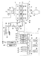
まず、本発明に係るデュアル噴射型内燃機関の燃料噴射制御装置の概略構成が示されている図1を参照するに、機関1は4つの気筒1aを備えている。各気筒1aはそれぞれ対応する吸気枝管2を介して共通のサージタンク3に接続されている。サージタンク3は吸気ダクト4を介してエアフローメータ4aに接続され、エアフローメータ4aはエアクリーナ5に接続されている。吸気ダクト4内にはステップモータ6によって駆動されるスロットル弁7が配置されている。このスロットル弁7はアクセルペダル10の踏み込みにほぼ連動して吸気ダクト4を開閉する。一方、各気筒1aは共通の排気マニホルド8に連結され、この排気マニホルド8は三元触媒コンバータ9に連結されている。
Hereinafter, embodiments of the present invention will be described with reference to the drawings.
First, referring to FIG. 1 showing a schematic configuration of a fuel injection control device for a dual injection internal combustion engine according to the present invention, the
各気筒1aには、筒内に向けて燃料を噴射するための筒内噴射用インジェクタ11と吸気ポートまたは吸気通路内に向けて燃料を噴射するための吸気ポート噴射用インジェクタ12とがそれぞれ取り付けられている。これらインジェクタ11、12は電子制御ユニット30の出力信号に基づいてそれぞれ制御される。また、各筒内噴射用インジェクタ11は共通の燃料分配管13に接続されており、この燃料分配管13は燃料分配管13に向けて流通可能な逆止弁14を介して、機関駆動式の高圧燃料ポンプ15に接続されている。
Each
図1に示すように、高圧燃料ポンプ15の吐出側はスピル電磁弁15aを介して高圧燃料ポンプ15の吸入側に連結されており、このスピル電磁弁15aの開度が小さいとき程、高圧燃料ポンプ15から燃料分配管13内に供給される燃料量が増大され、スピル電磁弁15aが全開にされると、高圧燃料ポンプ15から燃料分配管13への燃料供給が停止されるように構成されている。なお、スピル電磁弁15aは電子制御ユニット30の出力信号に基づいて制御される。
As shown in FIG. 1, the discharge side of the high-
一方、各吸気ポート噴射用インジェクタ12は共通の燃料分配管16に接続されており、燃料分配管16および高圧燃料ポンプ15は共通の燃料圧レギュレータ17を介して、電動モータ駆動式の低圧燃料ポンプ18に接続されている。さらに、低圧燃料ポンプ18は燃料フィルタ19を介して燃料タンク20に接続されている。燃料圧レギュレータ17は低圧燃料ポンプ18から吐出された燃料の燃料圧が予め定められた設定燃料圧よりも高くなると、低圧燃料ポンプ18から吐出された燃料の一部を燃料タンク20に戻すように構成されており、したがって吸気ポート噴射用インジェクタ12に供給されている燃料圧および高圧燃料ポンプ15に供給されている燃料圧が上記設定燃料圧よりも高くなるのを阻止している。さらに、図1に示すように、高圧燃料ポンプ15と燃料圧レギュレータ17との間には流通弁21が設けられている。この流通弁21は通常開弁されており、この流通弁21が閉弁されると低圧燃料ポンプ18から高圧燃料ポンプ15への燃料供給が停止される。なお、この流通弁21の開閉は電子制御ユニット30の出力信号に基づいて制御される。
On the other hand, each intake
また、電子制御ユニット30はデジタルコンピュータからなり、双方向性バス31を介して相互に接続されたROM(リードオンリメモリ)32、RAM(ランダムアクセスメモリ)33、CPU(マイクロプロセッサ)34、入力ポート35および出力ポート36を具備している。エアフローメータ4aは吸入空気量に比例した出力電圧を発生し、このエアフローメータ4aの出力電圧はAD変換器37を介して入力ポート35に入力される。機関1には機関冷却水温に比例した出力電圧を発生する水温センサ38が取付けられ、この水温センサ38の出力電圧はAD変換器39を介して入力ポート35に入力される。
The
燃料分配管13には燃料分配管13内の燃料圧に比例した出力電圧を発生する燃料圧センサ40が取付けられ、この燃料圧センサ40の出力電圧はAD変換器41を介して入力ポート35に入力される。触媒9上流の排気マニホルド8には排気ガス中の酸素濃度に比例した出力電圧を発生する空燃比センサ42が取付けられ、この空燃比センサ42の出力電圧はAD変換器43を介して入力ポート35に入力される。アクセルペダル10はアクセルペダル10の踏込み量に比例した出力電圧を発生するアクセル開度センサ44に接続され、アクセル開度センサ44の出力電圧はAD変換器45を介して入力ポート35に入力される。また、入力ポート35には機関回転数を表す出力パルスを発生する回転数センサ46が接続されている。電子制御ユニット30のROM32には、上述のアクセル開度センサ44ないしはエアフローメータ4aおよび回転数センサ46により得られる機関負荷率および機関回転数に基づき、運転状態に対応させて設定されている基本燃料噴射量の値や機関冷却水温に基づく補正値等が予めマップ化されて記憶されている。
A
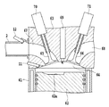
さらに、図2には気筒1aの側断面図が示されている。図2を参照するに、61はシリンダブロック、62は頂面上に凹部62aが形成されたピストン、63はシリンダブロック61上に固締されたシリンダヘッド、64はピストン62とシリンダヘッド63間に形成された燃焼室、65は吸気バルブ、66は排気バルブ、67は吸気ポート、68は排気ポート、69は点火プラグをそれぞれ示している。吸気ポート67は燃焼室64内に流入した空気がシリンダ軸線周りの旋回流を発生するように形成されている。凹部62aは筒内噴射用インジェクタ11側に位置するピストン62の周縁部からピストン62中央部に向かって延び、また点火プラグ69の下方において上方に延びるように形成されている。
Furthermore, FIG. 2 shows a side sectional view of the
また、吸気バルブ65および排気バルブ66は、それぞれ、吸気バルブ駆動機構70および排気バルブ駆動機構71に連係されている。吸気バルブ駆動機構70および排気バルブ駆動機構71は、励磁電流が印加されたときに発生する電磁力を利用して、それぞれ、吸気バルブ65と排気バルブ66とを進退駆動する電磁駆動機構から構成され、電子制御ユニット30の信号に基づき、開閉のタイミングおよびリフト量が任意に制御可能に構成されている。従って、例えば電子制御ユニット30からの信号に基づいて吸気バルブ駆動機構70および/または排気バルブ駆動機構71が作動されると、吸気バルブ65および/または吸気バルブ65の開閉時期、延いては開期間が長く或いは短く可変制御されることになる。
The
ここで、電子制御ユニット30の出力ポート36は対応する駆動回路47を介して、ステップモータ6、各筒内噴射用インジェクタ11、各吸気ポート噴射用インジェクタ12、スピル電磁弁15a、流通弁21、点火プラグ69や吸気バルブ駆動機構70および排気バルブ駆動機構71等に接続されている。
Here, the
なお、本実施の形態におけるエンジン1では、例えば、図3に示すような運転領域ないしは条件に対応して、燃焼形態が設定されると共に、筒内噴射用インジェクタ11と吸気通路噴射用インジェクタ12とによる噴射の分担率xが定められている。ここで、分担率xとは、全燃料噴射量に対して吸気通路噴射用インジェクタ12から噴射される燃料量の割合の意味で用い、分担率x%のとき筒内噴射用インジェクタ11から噴射される燃料量の割合は(100−x)%となる。そして、図3において、成層リーン領域「1」は、筒内噴射用インジェクタ11のみから噴射が行なわれる分担率0%領域であることを意味し、均質リーン領域「2」および均質ストイキ領域「3」は、吸気通路噴射用インジェクタ12からの噴射が分担率x%、筒内噴射用インジェクタ11からの噴射が(100−x)%で行われる領域であることを意味している。このxの値は、用いられるエンジン1に要求される運転条件に応じて、適度に変えられるものである。
In the
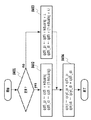
次に、上記電子制御ユニット30により実行される各種制御のうち、空燃比フィードバック制御による燃料噴射制御の第1実施形態に係る燃料噴射量算出ルーチンについて、図4に示すフローチャートを参照して説明する。このルーチンは、例えばクランク角度が所定角度進む毎に実行される。なお、このルーチンとは別に、空燃比フィードバック補正量「qdfi」が排気系に設けられた空燃比センサ42による空燃比の検出値と目標空燃比との差から求められている。そこで、この燃料噴射量算出ルーチンにおけるステップS401では、エンジン1が定常状態か否かが判断される。この定常状態か否かの判断は、電子制御ユニット30に入力される運転状態を示す各種パラメータのうち、例えば、アクセル開度センサ44により得られる機関負荷率の変動に基づき行なわれる。機関負荷率の変動がない、あるいは所定値を超えないときは定常状態にあるとして、ステップS402に進む。
Next, a fuel injection amount calculation routine according to the first embodiment of the fuel injection control by the air-fuel ratio feedback control among the various controls executed by the
このステップS402においては、上述の空燃比フィードバック補正量「qdfi」が、運転状態に応じた筒内噴射用インジェクタ11および吸気ポート噴射用インジェクタ12からの分担率に応じて分配され、筒内噴射用インジェクタ11に対する反映後のフィードバック補正量「qdfi_di」および吸気ポート噴射用インジェクタ12に対する反映後のフィードバック補正量「qdfi_pi」がそれぞれ下式により求められる。
In this step S402, the air-fuel ratio feedback correction amount “qdfi” described above is distributed according to the sharing ratio from the in-
qdfi_pi=qdfi×kdualsj
qdfi_di=qdfi×(1−kdualsj)
ここで、「kdualsj」は、機関負荷率および回転数に基づき求められる上記運転状態における吸気ポート噴射用インジェクタ12からの燃料噴射比率(上述の分担率xに相当する)であり、この場合には、筒内噴射用インジェクタ11からの燃料噴射比率は「1−kdualsj」であるから、両インジェクタの分担率に対応して同じ比率で空燃比フィードバック補正量が反映されている。例えば、「kdualsj」=0.8(すなわち、80%)の場合は、「1−kdualsj」=0.2であり、空燃比フィードバック補正量「qdfi」はこの比率80:20の通り、両インジェクタに反映されるのである。
qdfi_pi = qdfi × kdualsj
qdfi_di = qdfi × (1-kdualsj)
Here, “kdualsj” is the fuel injection ratio (corresponding to the above-described sharing ratio x) from the
一方、ステップS401の判断で、定常状態でない、すなわち加速状態等の所定の運転条件であると判断されると、ステップS403に進み、フィードバック補正量の反映比率が筒内噴射用インジェクタ11と吸気ポート噴射用インジェクタ12とで異ならせられて、筒内噴射用インジェクタ11に対する反映後のフィードバック補正量「qdfi_di」および吸気ポート噴射用インジェクタ12に対する反映後のフィードバック補正量「qdfi_pi」がそれぞれ例えば下式により求められる。
qdfi_pi=qdfi×kdualsj×λ
qdfi_di=qdfi×(1−kdualsj×λ)
On the other hand, if it is determined in step S401 that the engine is not in a steady state, that is, is in a predetermined operating condition such as an acceleration state, the process proceeds to step S403, where the feedback correction amount is reflected in the in-
qdfi_pi = qdfi × kdualsj × λ
qdfi_di = qdfi × (1-kdualsj × λ)
すなわち、吸気ポート噴射用インジェクタ12からの燃料噴射比率が「kdualsj」の場合には、これを例えばλ倍し、吸気ポート噴射用インジェクタ12の方が筒内噴射用インジェクタ11に対するのよりも大きい比率で、空燃比フィードバック補正量が反映されるようにされるのである。
That is, when the fuel injection ratio from the
そして、ステップS402およびステップS403の後は、ステップS404に進み、上記運転状態における両インジェクタの分担率に対応するそれぞれの基本燃料噴射量「qcyl_pi」、「qcyl_di」に対して、上述のステップS402またはステップS403にて求められた筒内噴射用インジェクタ11および吸気ポート噴射用インジェクタ12に対する反映後のフィードバック補正量が付加されて、吸気ポート噴射用インジェクタ12からの燃料噴射量「qinji」および筒内噴射用インジェクタ11からの燃料噴射量「qinjidi」が下式により算出される。
qinji=qcyl_pi+qdfi_pi
qinjidi=qcyl_di+qdfi_di
Then, after step S402 and step S403, the process proceeds to step S404, and for each basic fuel injection amount “qcyl_pi”, “qcyl_di” corresponding to the share ratio of both injectors in the above operating state, the above-described step S402 or The feedback correction amount after reflection for the in-
qinji = qcyl_pi + qdfi_pi
qinjidi = qcyl_di + qdfi_di
そして、この求められた燃料噴射量「qinji」および「qinjidi」が、吸気ポート噴射用インジェクタ12および筒内噴射用インジェクタ11からそれぞれ噴射される。このように、本実施の形態では、加速時において、空燃比フィードバック補正量の反映比率が、吸気ポート噴射用インジェクタ12の方が筒内噴射用インジェクタ11に対するのよりも大きいので、ポートウエット分が加重して補正されることになる。従って、燃料の供給遅れが発生する可能性が軽減され、空燃比制御性が向上し、エミッションや応答性および燃費を向上させることができる。
The determined fuel injection amounts “qinji” and “qinjidi” are respectively injected from the
次に、上記電子制御ユニット30により実行される各種制御のうち、空燃比フィードバック制御による燃料噴射制御の第2実施形態に係る燃料噴射量算出ルーチンについて、図5に示すフローチャートを参照して説明する。このルーチンも、前実施形態と同様に、例えばクランク角度が所定角度進む毎に実行される。この第2実施形態における燃料噴射量算出ルーチンでは、まず、ステップS501において、均質リーン運転中か否か、すなわち、図3の領域「2」内における運転中か否かが判断される。ここで、均質リーン運転中であり、「yes」の場合は、ステップS502に進み、ストイキ要求があるか否かが判断される。この判断は運転状態を表すパラメータであるエンジンの回転数および負荷率に基づいて行なわれ、「yes」の場合は、ステップS503に進み、さらに加速要求があるか否かが判断される。これらのステップS501ないしS503の判断によって、均質リーン領域「2」から均質ストイキ領域「3」に入った場合の最初の加速か否かが判断されることになる。そこで、加速要求あり、すなわち「yes」の場合は、ステップS504で加速要求フラグ「exaccsj」をオン(すなわち、1)にした後、ステップS505に進み、フィードバック補正量の反映比率が筒内噴射用インジェクタ11と吸気ポート噴射用インジェクタ12とで異ならせられて、吸気ポート噴射用インジェクタ12に対する反映後のフィードバック補正量「qdfi_pi」および筒内噴射用インジェクタ11に対する反映後のフィードバック補正量「qdfi_di」がそれぞれ例えば下式により求められる。
qdfi_pi=qdfi×(1−kdualsjd×λ)
qdfi_di=qdfi×kdualsjd×λ
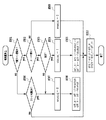
Next, a fuel injection amount calculation routine according to the second embodiment of the fuel injection control by the air-fuel ratio feedback control among the various controls executed by the
qdfi_pi = qdfi × (1-kdualsjd × λ)
qdfi_di = qdfi × kdualsjd × λ
すなわち、吸気ポート噴射用インジェクタ12からの燃料噴射比率が「kdualsj」の場合には、筒内噴射用インジェクタ11からの燃料噴射比率は「kdualsjd」(上述の分担率(100−x)に相当する)であり、これを例えばλ倍し、筒内噴射用インジェクタ11の方が吸気ポート噴射用インジェクタ12に対するのよりも大きい比率で、空燃比フィードバック補正量が反映されるようにされる。
That is, when the fuel injection ratio from the
一方、ステップS501の判断で、均質リーン運転中でないと判断されたときは、ステップS506に進み、均質ストイキ領域「3」運転中か否かが判断される。「yes」の場合は、ステップS507に進み、加速要求フラグ「exaccsj」をオフ(すなわち、0)にした後、ステップS508に進み、空燃比フィードバック補正量「qdfi」が、運転状態に応じた筒内噴射用インジェクタ11および吸気ポート噴射用インジェクタ12からの分担率に応じて分配され、吸気ポート噴射用インジェクタ12に対する反映後のフィードバック補正量「qdfi_pi」および筒内噴射用インジェクタ11に対する反映後のフィードバック補正量「qdfi_di」がそれぞれ下式により求められる。
qdfi_pi=qdfi×(1−kdualsjd)
qdfi_di=qdfi×kdualsjd
On the other hand, if it is determined in step S501 that the homogeneous lean operation is not being performed, the process proceeds to step S506, where it is determined whether or not the homogeneous stoichiometric region “3” is being operated. In the case of “yes”, the process proceeds to step S507, the acceleration request flag “exaccsj” is turned off (that is, 0), and then the process proceeds to step S508, where the air-fuel ratio feedback correction amount “qdfi” is set to the cylinder corresponding to the operating state. The feedback correction amount “qdfi_pi” after distribution to the
qdfi_pi = qdfi x (1-kdualsjd)
qdfi_di = qdfi × kdualsjd
そして、上述のステップS505およびステップS508の後は、いずれもステップS510に進み、上記運転状態における両インジェクタの分担率に対応するそれぞれの基本燃料噴射量「qcyl_pi」、「qcyl_di」に対して、上述のステップS505またはステップS508にて求められた筒内噴射用インジェクタ11および吸気ポート噴射用インジェクタ12に対する反映後のフィードバック補正量が付加されて、吸気ポート噴射用インジェクタ12からの燃料噴射量「qinji」および筒内噴射用インジェクタ11からの燃料噴射量「qinjidi」が下式により算出される。
qinji=qcyl_pi+qdfi_pi
qinjidi=qcyl_di+qdfi_di
After step S505 and step S508 described above, both proceed to step S510, and the basic fuel injection amounts “qcyl_pi” and “qcyl_di” corresponding to the share ratios of the two injectors in the above operating state are described above. The feedback correction amount after reflection for the in-
qinji = qcyl_pi + qdfi_pi
qinjidi = qcyl_di + qdfi_di
そして、この求められた燃料噴射量「qinji」および「qinjidi」が、吸気ポート噴射用インジェクタ12および筒内噴射用インジェクタ11からそれぞれ噴射される。なお、上述のステップS502において、ストイキ要求がない場合にはステップS509に進み、加速要求フラグ「exaccsj」をオフ(すなわち、0)にした後、上述のステップS510に進む。また、この加速要求フラグ「exaccsj」は、均質リーン運転に復帰したとき、および加速要求終了後の所定期間経過後にクリアされる。このように、本第2実施形態においては、所定の運転条件が均質リーン運転領域から均質ストイキ領域に入ってからの加速時であるときに、空燃比フィードバック補正量「qdfi」の反映比率が、筒内噴射用インジェクタ11の方が吸気ポート噴射用インジェクタ12に対するのよりも大きくされているので、ポートウエット分の補正は遅れるが、この分筒内に直接に噴射される燃料量が増大されて、要求に応じて応答性を向上させることができるのである。
The determined fuel injection amounts “qinji” and “qinjidi” are respectively injected from the
さらに、空燃比フィードバック制御による燃料噴射制御の第3実施形態に係る燃料噴射量算出ルーチンについて、図6に示すフローチャートを参照して説明する。このルーチンも、前実施形態と同様に、例えばクランク角度が所定角度進む毎に実行される。この第3実施形態における燃料噴射量算出ルーチンでは、まず、ステップS601において、空燃比リミット制御中であるか否かが判断される。この空燃比リミット制御とは、NOxや燃費の低減を図るべく、目標空燃比を点火プラグによる着火によっての燃焼が可能なリーン限界(例えば、空燃比26程度)に設定し、この近傍において燃焼を行なわせるための制御であり、本実施の形態においては、均質リーン領域「2」において過渡状態ではない定常状態にあることを前提として行なわれる。従って、この空燃比リミット制御中には、所定のリミット補正量を基本燃料噴射量に対し増減した結果として生ずるエンジン1の安定度の変動を、例えば、所定のクランク角(例えば、30°)毎の回転数変動が所定の閾値を超えるか否かにより判断しつつ、目標空燃比のリーン限界に近づけるような制御が行なわれる。なお、このリミット補正量とは、前述の空燃比フィードバック補正量が目標空燃比と検出空燃比との差に応じた大きさであるのに対し、一定値である。
Further, a fuel injection amount calculation routine according to the third embodiment of the fuel injection control by the air-fuel ratio feedback control will be described with reference to the flowchart shown in FIG. Similarly to the previous embodiment, this routine is also executed each time the crank angle advances by a predetermined angle, for example. In the fuel injection amount calculation routine in the third embodiment, first, in step S601, it is determined whether air-fuel ratio limit control is being performed. In this air-fuel ratio limit control, in order to reduce NOx and fuel consumption, the target air-fuel ratio is set to a lean limit (for example, about an air-fuel ratio of about 26) that allows combustion by ignition with an ignition plug, and combustion is performed in the vicinity thereof. In the present embodiment, the control is performed on the assumption that the homogeneous lean region “2” is in a steady state that is not a transient state. Accordingly, during this air-fuel ratio limit control, fluctuations in the stability of the
そこで、ステップS601において、かかる空燃比リミット制御中であると判断されると、ステップS602に進み、上述のリミット補正量の増減量要求があるか否かが判断される。増減量要求がある、すなわち「yes」のときはステップS603に進み、増量要求か減量要求かが判断される。これは、上述のエンジン1の安定度の変動に基づき判断され、安定度が損なわれない限り前回の増量または減量制御を継続させて、目標空燃比のリーン限界に近づけるような制御が行なわれることになる。そこで、ステップS603の判断で増量要求である場合は、ステップS604に進み、分担率にかかわらず、吸気ポート噴射用インジェクタ12からの燃料噴射量「qinji」が、基本燃料噴射量「qcyl_pi」に対してポート噴射用リミット補正量「qlimit_pi」分増大されるようにして、下式により算出される。
qinji=qcyl_pi+qlimit_pi
Therefore, if it is determined in step S601 that the air-fuel ratio limit control is being performed, the process proceeds to step S602, where it is determined whether or not there is a request for increase / decrease in the limit correction amount. If there is an increase / decrease request, that is, “yes”, the process proceeds to step S603, where it is determined whether an increase request or a decrease request. This is determined on the basis of the above-described fluctuation in the stability of the
qinji = qcyl_pi + qlimit_pi
そして、減量側の連続補正回数を表す「cntlimitd」はクリアされ、増量側の連続補正回数を表す「cntlimita」が1だけインクリメントされる。そこで、ステップS605に進み、この増量側連続補正回数「cntlimita」が所定回数αを超えたか否かが判断され、所定回数αを超えているときにはステップS607へ進み、超えていないときはステップS606に進んで、筒内噴射用リミット補正量「qlimit_di」を「0」にした後、ステップS607へ進む。かくて、ステップS607においては、筒内噴射用インジェクタ11からの燃料噴射量「qinjidi」が、基本燃料噴射量「qcyl_di」に対して筒内噴射用リミット補正量「qlimit_di」分増大されるようにして、下式により算出される。
qinjidi=qcyl_di+qlimit_di
Then, “cntlimitd” indicating the number of continuous corrections on the decrease side is cleared, and “cntlimita” indicating the number of continuous corrections on the increase side is incremented by one. Therefore, the process proceeds to step S605, where it is determined whether or not the increase-side continuous correction count “cntlimita” has exceeded the predetermined number α. If the predetermined number α has been exceeded, the process proceeds to step S607, and if not, the process proceeds to step S606. Then, after the in-cylinder injection limit correction amount “qlimit_di” is set to “0”, the process proceeds to step S607. Thus, in step S607, the fuel injection amount “qinjidi” from the in-
qinjidi = qcyl_di + qlimit_di
しかしながら、この筒内噴射用リミット補正量「qlimit_di」は、上述のように、増量側連続補正回数「cntlimita」が所定回数αを超えていないときは「0」であるから、この場合には、筒内噴射用リミット補正量「qlimit_di」は筒内噴射用インジェクタ11からの燃料噴射量「qinjidi」には何等反映されることがなく、所定回数αを超えて始めて反映されることになる。
However, the in-cylinder injection limit correction amount “qlimit_di” is “0” when the increase-side continuous correction number “cntlimita” does not exceed the predetermined number α, as described above. The in-cylinder injection limit correction amount “qlimit_di” is not reflected at all in the fuel injection amount “qinjidi” from the in-
一方、ステップS603の判断で減量要求である場合は、ステップS608に進み、分担率にかかわらず、吸気ポート噴射用インジェクタ12からの燃料噴射量「qinji」が、基本燃料噴射量「qcyl_pi」に対してポート噴射用リミット補正量「qlimit_pi」分減量されるようにして、下式により算出される。
qinji=qcyl_pi−qlimit_pi
On the other hand, if it is determined that the amount is to be reduced in step S603, the process proceeds to step S608, and the fuel injection amount “qinji” from the
qinji = qcyl_pi−qlimit_pi
そして、増量側の連続補正回数を表す「cntlimita」はクリアされ、減量側の連続補正回数を表す「cntlimitd」が1だけインクリメントされる。そこで、ステップS609に進み、この減量側連続補正回数「cntlimitd」が所定回数βを超えたか否かが判断され、所定回数βを超えているときにはステップS611へ進み、超えていないときはステップS610に進んで、筒内噴射用リミット補正量「qlimit_di」を「0」にした後、ステップS611へ進む。かくて、ステップS611においては、筒内噴射用インジェクタ11からの燃料噴射量「qinjidi」が、基本燃料噴射量「qcyl_di」に対して筒内噴射用リミット補正量「qlimit_di」分減量されるようにして、下式により算出される。
qinjidi=qcyl_di−qlimit_di
Then, “cntlimita” indicating the number of continuous corrections on the increase side is cleared, and “cntlimitd” indicating the number of continuous corrections on the decrease side is incremented by one. Therefore, the process proceeds to step S609, where it is determined whether or not the decrease-side continuous correction count “cntlimitd” exceeds the predetermined number β. If it exceeds the predetermined number β, the process proceeds to step S611, and if not, the process proceeds to step S610. Then, after the in-cylinder injection limit correction amount “qlimit_di” is set to “0”, the process proceeds to step S611. Thus, in step S611, the fuel injection amount “qinjidi” from the in-
qinjidi = qcyl_di−qlimit_di
しかしながら、この筒内噴射用リミット補正量「qlimit_di」は、上述のように、減量側連続補正回数「cntlimitd」が所定回数βを超えていないときは「0」であるから、この場合には、筒内噴射用リミット補正量「qlimit_di」は筒内噴射用インジェクタ11からの燃料噴射量「qinjidi」には何等反映されることがなく、所定回数βを超えて始めて反映されることになる。
However, the in-cylinder injection limit correction amount “qlimit_di” is “0” when the reduction-side continuous correction number “cntlimitd” does not exceed the predetermined number β, as described above. The in-cylinder injection limit correction amount “qlimit_di” is not reflected in the fuel injection amount “qinjidi” from the in-
このように、本実施の形態による制御では、空燃比リミット制御中における空燃比フィードバック補正の反映比率が、増量側連続補正回数「cntlimita」が所定回数α、または減量側連続補正回数「cntlimitd」が所定回数βかの一定量の燃料増減範囲内においては、吸気ポート噴射用インジェクタに対して100%とされる、換言すると、空燃比フィードバック補正が吸気ポート噴射用インジェクタ12に対してのみ反映される。そして、かかる一定量の燃料増減範囲を超えても増減量要求のあるときに、初めて、筒内噴射用インジェクタ11へも反映されるのである。かくて、空燃比リミット制御中において増減量要求があるときに、一定量の燃料増減範囲内においては、空燃比フィードバック補正が吸気ポート噴射用インジェクタ12に対してのみ反映される、換言すると、筒内噴射用インジェクタ11へは反映されず現状が維持されるので、安定的に着火される空燃比が筒内の点火ギャップ近傍に維持されることになる。従って、リーン運転を安定して継続でき、燃費を低減することができるのである。
Thus, in the control according to the present embodiment, the reflection ratio of the air-fuel ratio feedback correction during the air-fuel ratio limit control is such that the increase-side continuous correction count “cntlimita” is the predetermined count α or the decrease-side continuous correction count “cntlimitd”. Within a certain amount of fuel increase / decrease range of the predetermined number β, it is set to 100% for the intake port injection injector, in other words, the air-fuel ratio feedback correction is reflected only to the intake
11 筒内噴射用インジェクタ
12 吸気ポート噴射用インジェクタ
30 電子制御ユニット
42 空燃比センサ
44 アクセル開度センサ(負荷センサ)
46 回転数センサ
11 In-
46 Speed sensor
Claims (4)
空燃比フィードバック補正の反映比率を、所定の運転条件に対応させて、筒内噴射用インジェクタと吸気ポート噴射用インジェクタとで異ならせて制御することを特徴とする内燃機関の燃料噴射制御装置。 In an internal combustion engine that includes an in-cylinder injector and an intake port injector, and injects fuel from each injector at an appropriate share rate according to the operating state,
A fuel injection control device for an internal combustion engine, characterized in that the reflection ratio of the air-fuel ratio feedback correction is controlled to be different between the in-cylinder injector and the intake port injector according to a predetermined operating condition.
Priority Applications (1)
| Application Number | Priority Date | Filing Date | Title |
|---|---|---|---|
| JP2004112241A JP2005299401A (en) | 2004-04-06 | 2004-04-06 | Fuel injection control device for internal combustion engine |
Applications Claiming Priority (1)
| Application Number | Priority Date | Filing Date | Title |
|---|---|---|---|
| JP2004112241A JP2005299401A (en) | 2004-04-06 | 2004-04-06 | Fuel injection control device for internal combustion engine |
Publications (1)
| Publication Number | Publication Date |
|---|---|
| JP2005299401A true JP2005299401A (en) | 2005-10-27 |
Family
ID=35331274
Family Applications (1)
| Application Number | Title | Priority Date | Filing Date |
|---|---|---|---|
| JP2004112241A Pending JP2005299401A (en) | 2004-04-06 | 2004-04-06 | Fuel injection control device for internal combustion engine |
Country Status (1)
| Country | Link |
|---|---|
| JP (1) | JP2005299401A (en) |
-
2004
- 2004-04-06 JP JP2004112241A patent/JP2005299401A/en active Pending
Similar Documents
| Publication | Publication Date | Title |
|---|---|---|
| JP4649142B2 (en) | Ignition timing control device for internal combustion engine | |
| JP3815100B2 (en) | Engine control device | |
| US6978762B2 (en) | Control system for internal combustion engine | |
| KR100294713B1 (en) | Control device of injection type spark ignition type internal combustion engine | |
| KR100309757B1 (en) | Combustion control device of lean burn internal combustion engine | |
| US7610899B2 (en) | Control apparatus for internal combustion engine | |
| JPH1068375A (en) | Ignition timing control system for in-cylinder injection internal combustion engine | |
| US7121261B2 (en) | Fuel supply apparatus for internal combustion engine | |
| JP3175601B2 (en) | Air intake control system for lean burn engine | |
| JPH1193731A (en) | Fuel injection control device for in-cylinder injection internal combustion engine | |
| US7343900B2 (en) | Ignition timing controller of internal combustion engine | |
| WO1998026169A1 (en) | Combustion control device for internal combustion engine | |
| JP4927798B2 (en) | Fuel injection control device for internal combustion engine | |
| JP4453566B2 (en) | Control device for internal combustion engine | |
| JP4466328B2 (en) | Fuel injection control method for dual injection internal combustion engine | |
| JP3882630B2 (en) | Control device for spark ignition direct injection engine | |
| JP2005307756A (en) | Fuel injection control device for internal combustion engine | |
| JP3735138B2 (en) | Intake control device | |
| JP4600607B2 (en) | Control device for internal combustion engine | |
| JP2000220504A (en) | Idle speed control system for in-cylinder injection engine | |
| JP2005201073A (en) | Control device for internal combustion engine | |
| JP2005337201A (en) | Control device for internal combustion engine | |
| JP2005325717A (en) | Fuel injection control method for internal combustion engine | |
| JP2007032355A (en) | Engine control device | |
| JPH07116968B2 (en) | Air-fuel ratio controller for internal combustion engine |
Legal Events
| Date | Code | Title | Description |
|---|---|---|---|
| A621 | Written request for application examination |
Free format text: JAPANESE INTERMEDIATE CODE: A621 Effective date: 20060630 |
|
| A131 | Notification of reasons for refusal |
Free format text: JAPANESE INTERMEDIATE CODE: A131 Effective date: 20081128 |
|
| A02 | Decision of refusal |
Free format text: JAPANESE INTERMEDIATE CODE: A02 Effective date: 20090728 |