JP2005299399A - Fuel shut-off valve - Google Patents
Fuel shut-off valve Download PDFInfo
- Publication number
- JP2005299399A JP2005299399A JP2004112203A JP2004112203A JP2005299399A JP 2005299399 A JP2005299399 A JP 2005299399A JP 2004112203 A JP2004112203 A JP 2004112203A JP 2004112203 A JP2004112203 A JP 2004112203A JP 2005299399 A JP2005299399 A JP 2005299399A
- Authority
- JP
- Japan
- Prior art keywords
- valve
- fuel
- float
- connection passage
- seat member
- Prior art date
- Legal status (The legal status is an assumption and is not a legal conclusion. Google has not performed a legal analysis and makes no representation as to the accuracy of the status listed.)
- Withdrawn
Links
- 239000000446 fuel Substances 0.000 title claims abstract description 81
- 239000002828 fuel tank Substances 0.000 claims abstract description 37
- 230000001681 protective effect Effects 0.000 claims description 10
- 239000000463 material Substances 0.000 abstract description 2
- 239000012530 fluid Substances 0.000 abstract 1
- 239000011435 rock Substances 0.000 abstract 1
- 239000004698 Polyethylene Substances 0.000 description 6
- 210000000078 claw Anatomy 0.000 description 6
- -1 polyethylene Polymers 0.000 description 6
- 229920000573 polyethylene Polymers 0.000 description 6
- 239000007788 liquid Substances 0.000 description 5
- 230000002093 peripheral effect Effects 0.000 description 4
- 238000003466 welding Methods 0.000 description 4
- 229930182556 Polyacetal Natural products 0.000 description 3
- 229920006324 polyoxymethylene Polymers 0.000 description 3
- 230000000694 effects Effects 0.000 description 2
- 239000004677 Nylon Substances 0.000 description 1
- OFOBLEOULBTSOW-UHFFFAOYSA-N Propanedioic acid Natural products OC(=O)CC(O)=O OFOBLEOULBTSOW-UHFFFAOYSA-N 0.000 description 1
- 230000000903 blocking effect Effects 0.000 description 1
- 239000002131 composite material Substances 0.000 description 1
- 239000000805 composite resin Substances 0.000 description 1
- 230000007423 decrease Effects 0.000 description 1
- 238000010586 diagram Methods 0.000 description 1
- 239000000295 fuel oil Substances 0.000 description 1
- 239000011976 maleic acid Substances 0.000 description 1
- VZCYOOQTPOCHFL-UPHRSURJSA-N maleic acid group Chemical group C(\C=C/C(=O)O)(=O)O VZCYOOQTPOCHFL-UPHRSURJSA-N 0.000 description 1
- 238000012986 modification Methods 0.000 description 1
- 230000004048 modification Effects 0.000 description 1
- 238000000465 moulding Methods 0.000 description 1
- 229920001778 nylon Polymers 0.000 description 1
- 238000004080 punching Methods 0.000 description 1
- 239000011347 resin Substances 0.000 description 1
- 229920005989 resin Polymers 0.000 description 1
- 230000000717 retained effect Effects 0.000 description 1
- 230000000630 rising effect Effects 0.000 description 1
- 239000000057 synthetic resin Substances 0.000 description 1
- 229920003002 synthetic resin Polymers 0.000 description 1
- VZCYOOQTPOCHFL-UHFFFAOYSA-N trans-butenedioic acid Natural products OC(=O)C=CC(O)=O VZCYOOQTPOCHFL-UHFFFAOYSA-N 0.000 description 1
- 238000011144 upstream manufacturing Methods 0.000 description 1
Images

Landscapes
- Cooling, Air Intake And Gas Exhaust, And Fuel Tank Arrangements In Propulsion Units (AREA)
- Self-Closing Valves And Venting Or Aerating Valves (AREA)
Abstract
Description
本発明は、燃料タンクの上部に装着され、燃料タンク内と外部とを接続する接続通路を開閉することで燃料タンクと外部とを連通遮断する燃料遮断弁に関する。 The present invention relates to a fuel cutoff valve that is attached to an upper part of a fuel tank and that opens and closes a connection passage that connects the inside and outside of the fuel tank to cut off communication between the fuel tank and the outside.
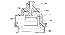
従来、この種の燃料遮断弁として、特許文献1などが知られており、図10に示すような構成である。図10は燃料遮断弁100の上部を示す断面図である。燃料遮断弁100は、外部に接続される接続通路112に連通する弁室110Sを有するケーシング110と、弁室110Sに収納され燃料タンクFT内の液面に応じて昇降するフロート120と、フロート120の上に配置されたバルブシート130と、フロート120を上方に付勢するスプリング(図示省略)とを備えている。フロート120は、燃料から浮力を受けることで上昇し、バルブシート130が接続通路112を閉じることで外部(キャニスタ)への燃料の流出を防止している。
Conventionally, as this kind of fuel cutoff valve,
そして、燃料の液面が下がり、フロート120が下がったときにフロート120の自重を利用して、フロート120の上部に形成されている爪122でバルブシート130を剥がすことでバルブシート130の張り付きを防ぎ、再開弁特性を向上させている。
Then, when the fuel level is lowered and the
しかし、従来の燃料遮断弁100では、車両の急旋回や振動などにより急激な燃料の揺動が生じたときに、バルブシート130が接続通路112を速やかに閉じることができず、燃料が接続通路112から流出することがある。
However, in the conventional fuel shut-off
本発明は、上記従来の技術の問題点を踏まえ、車両の急旋回や振動などにより燃料タンク内の燃料が揺動しても、接続通路から外部へ燃料の流出を確実に防止する燃料遮断弁を提供することを目的とする。 The present invention is based on the above-mentioned problems of the prior art, and even if the fuel in the fuel tank is swung due to sudden turning or vibration of the vehicle, the fuel cutoff valve reliably prevents the fuel from flowing out from the connection passage. The purpose is to provide.
上記課題を解決するためになされた本発明は、
燃料タンクの上部に装着され、燃料タンク内と外部とを連通遮断する燃料遮断弁において、
上記燃料タンク内に連通する弁室を有するケーシングと、
上記ケーシングの上部に設けられ、上記弁室内と外部とを接続する接続通路と、
上記弁室内に収納され上記燃料タンク内の燃料液位に応じて昇降するフロートと、上記フロートの上部に配置されたシート部材とを有する弁体機構と、
を備え、
上記弁体機構は、上記接続通路に近接しかつケーシングの内壁面に設けられ、上記シート部材が上記接続通路を開閉可能であるように上記シート部材の一端を支持する弁支持部を有すること、を特徴とする。
The present invention made to solve the above problems
In the fuel shut-off valve that is attached to the upper part of the fuel tank and cuts off the communication between the inside and outside of the fuel tank.
A casing having a valve chamber communicating with the fuel tank;
A connection passage provided at an upper portion of the casing and connecting the valve chamber and the outside;
A valve body mechanism that includes a float that is housed in the valve chamber and moves up and down according to a fuel level in the fuel tank; and a seat member that is disposed above the float;
With
The valve body mechanism is provided on the inner wall surface of the casing close to the connection passage, and has a valve support portion that supports one end of the seat member so that the seat member can open and close the connection passage. It is characterized by.
本発明にかかる燃料遮断弁を用いた燃料タンクにおいて、フロートが燃料によって上昇すると、フロートの上部に配置したシート部材が連動して接続通路を閉じ、燃料タンク内を外部に対して遮断して燃料の流出を防止する。 In the fuel tank using the fuel cutoff valve according to the present invention, when the float rises with the fuel, the seat member arranged at the upper part of the float interlocks to close the connection passage and shuts off the inside of the fuel tank from the outside. To prevent the outflow.
また、シート部材の一端が接続通路に近接した位置に設けたケーシングの弁支持部に支持されているので、車両旋回時の液面揺動時などの燃料液面が急激に上昇してフロートが燃料液位の上昇速度に追従できない場合であっても、シート部材が弁室から接続通路への経路を遮るから燃料の外部への流出を防止することができる。 Also, since one end of the seat member is supported by the valve support portion of the casing provided at a position close to the connection passage, the fuel liquid level suddenly rises when the liquid level fluctuates when the vehicle turns, etc. Even if it is not possible to follow the rising speed of the fuel level, the seat member blocks the path from the valve chamber to the connection passage, so that the fuel can be prevented from flowing out.
本発明の燃料遮断弁の好適な態様として、弁体機構は、フロートの上下の動きに連動してシート部材がフロートの上部などで押されることにより接続通路を開閉可能にする構成をとることができる。さらに、他の好適な態様として、弁体機構は、フロートの上部に形成された係合部を有し、該係合部は、上記シート部材が上記接続通路を閉じている状態から上記フロートが下降したときに、上記シート部材の他端に係合して上記シート部材が上記接続通路を開くように形成することができる。この構成により、燃料消費により燃料液位が下がることに伴ってフロートが下降すると、シート部材の他端が係合部に係合して、シート部材の一端を支点として接続通路を開く方向への力が加えられるから、再開弁をスムーズに行なわせることができる。 As a preferred aspect of the fuel cutoff valve according to the present invention, the valve body mechanism may be configured to open and close the connection passage when the seat member is pushed by the upper part of the float in conjunction with the vertical movement of the float. it can. Furthermore, as another preferred aspect, the valve body mechanism has an engagement portion formed at an upper portion of the float, and the engagement portion is configured so that the float is moved from a state where the seat member closes the connection passage. When lowered, the sheet member can be formed so as to engage with the other end of the sheet member to open the connection passage. With this configuration, when the float descends as the fuel level drops due to fuel consumption, the other end of the seat member is engaged with the engaging portion, and the connection passage is opened in the direction of opening one end of the seat member as a fulcrum. Since force is applied, the restart valve can be performed smoothly.
本発明にかかる燃料遮断弁の好適な態様として、フロートの上部であってシート部材を中心として弁支持部と反対側の部位に、弁室から接続通路に向かう経路を遮る防護壁を設ける構成をとることができる。 As a preferred embodiment of the fuel cutoff valve according to the present invention, a configuration is provided in which a protective wall is provided at a portion on the opposite side of the valve support portion with the seat member as the center and blocking the path from the valve chamber toward the connection passage. Can take.
以上説明した本発明の構成・作用を一層明らかにするために、以下本発明の好適な実施例について説明する。 In order to further clarify the configuration and operation of the present invention described above, preferred embodiments of the present invention will be described below.
(1) 燃料遮断弁10の概略構成
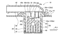
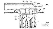
図1は本発明の第1の実施例にかかる自動車の燃料タンクFTの上部に取り付けられる燃料遮断弁10を示す断面図である。燃料遮断弁10は、燃料タンクFT内の燃料が所定の液位FL1に達したときに外部通路(キャニスタ)への通路を遮断して外部への燃料の流出を規制するものである。
(1) Schematic configuration of
燃料タンクFTは、その表面がポリエチレンを含む複合樹脂材料により形成されたタンク上壁FTaを備えており、このタンク上壁FTaに取付穴FTcが形成されている。タンク上壁FTaには、燃料遮断弁10が取付穴FTcに突入した状態にて取り付けられている。燃料遮断弁10は、ケーシング20と、フロート51およびシート部材55を有する弁体機構50と、スプリング60とを備え、燃料タンクFTの燃料液位に応じてフロート51を昇降させることによりキャニスタ(図示省略)への接続通路を開閉する。
The fuel tank FT includes a tank upper wall FTa whose surface is formed of a composite resin material containing polyethylene, and a mounting hole FTc is formed in the tank upper wall FTa. The
(2) 燃料遮断弁10の各部の構成
以下、燃料遮断弁10の各部の構成について説明する。
(2) Configuration of Each Part of
(2)−1 ケーシング20
ケーシング20は、ケーシング本体30と、底支持板35と、蓋体40とを備えている。ケーシング本体30および底支持板35は、耐燃料油性を有した合成樹脂ポリアセタールやナイロンなどから形成されている。蓋体40は、ポリエチレンを主体とする複合材料で形成されている。
(2) -1
The
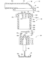
図2は燃料遮断弁10を分解した断面図である。ケーシング本体30は、天井壁部32と、この天井壁部32から下方へ円筒状に延設された側壁33とを備え、天井壁部32と側壁33とに囲まれたカップ状の弁室30Sを形成し、その下部を下開口30aとしている。天井壁部32の中央部には、下方に向けて上部突出部32aが形成されている。上部突出部32a内には、接続通路32bが貫通しており、接続通路32bの弁室30S側がシール部32cになっている。
FIG. 2 is an exploded cross-sectional view of the
また、側壁33は、弁室30Sと燃料タンクFT(図1)内とを連通する連通孔33aと、その下部に底支持板35を取り付けるための係合穴33bと、その上部に蓋体40に取り付けるためのフランジ部33cとを備えている。上記底支持板35は、ケーシング本体30の下開口30aの一部を閉じる部材であり、その外周部に形成された係合爪35aが上記係合穴33bに係合することにより、ケーシング本体30の下部に装着される。底支持板35の中央部には、弁室30Sに連通させるための連通孔35bが形成されている。
Further, the
蓋体40は、蓋本体41と、蓋本体41の中央から上部へL字形に突出した管体部42と、蓋本体41の外周に形成されたフランジ43と、蓋本体41の下面に形成された溶着面44とを備え、これらを一体に形成している。また、管体部42には、管体通路42aが形成されており、この管体通路42aの一端は、ケーシング本体30の接続通路32bに接続され、他端はキャニスタ側に接続されている。さらに、フランジ43の下端部には、燃料タンクFTのタンク上壁FTaに溶着される環状溶着部43aが形成されている。また、上記溶着面44は、ケーシング本体30のフランジ部33cに溶着されるように形成されており、例えば、マレイン酸変性された変性ポリエチレンを2色成形などにより積層している。変性ポリエチレンは、ポリアセタールおよびポリエチレンの両方に熱溶着性を有し、蓋体40とケーシング本体30とを接合する。
The
(2)−2 弁体機構50
弁体機構50は、フロート51と、フロート51の上方に配置されたシート部材55とを備えている。フロート51は、上壁部52と、その上壁部52の外周から下方に形成された筒状の側壁部53とを備えた容器形状に構成されており、その内側スペースが浮力を生じさせるための浮力室51Sになっている。また、フロート51の外周部に上下方向にガイド突条51aが複数形成されている。フロート51の浮力室51S内には、スプリング60が配置されている。スプリング60は、フロート51の一端と底支持板35の上面との間に介在することによりフロート51を上方へ付勢している。
(2) -2 Valve
The
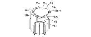
図3はフロート51およびシート部材55を示す斜視図である。フロート51の上壁部52には、その中央部に中央突部52aが形成されている。また、フロート51の上部の外周部には、防護壁52bがほぼ半周分だけ突設されている。図1に示すように防護壁52bは、ケーシング本体30から接続通路32bに向かう経路を遮る位置に突設されている。図3に戻り、防護壁52bの内周の一端部には、中心に向けた係合部52cが突設されている。係合部52cは、シート部材55の外周部の一端に係合する爪になっている。
FIG. 3 is a perspective view showing the
シート部材55は、円板状のプレートであるシート本体55aと、シート本体55aの一端部に突設されかつ爪55b−1を有する被支持端55bとを備え、樹脂により一体形成されている。シート本体55aの上面は、シート面55cになっている。図1に示すように、被支持端55bは、ケーシング本体30の上部内壁に揺動可能に支持されている。すなわち、ケーシング本体30の天井壁部32の内壁であって接続通路32bに近接した位置には、弁支持部32dが突設されている。弁支持部32dには、支持穴32d−1が形成されている。支持穴32d−1は、スライド型を用いた場合に型抜きを容易にするために連通孔33aと水平方向で同じ位置に形成されている。支持穴32d−1に、被支持端55bが圧入されて爪55b−1で抜止めされることにより、シート部材55は、被支持端55bおよび弁支持部32dを支点として揺動可能に支持され、シート面55cで接続通路32bを開閉する。
また、シート部材55の他端は、フロート51の係合部52cに係合するように形成されている。つまり、フロート51が上記接続通路32bを閉じている状態から下降したときに、シート部材55は、係合部52cに係合して、被支持端55bを支点にして接続通路32bを開くように形成されている(図5参照)。
The
Further, the other end of the
(3) 燃料遮断弁10の動作、その作用・効果
次に、燃料遮断弁10の開閉動作について説明する。
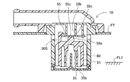
(3)−1 図1において、給油により燃料タンクFTに燃料が供給されると、燃料タンクFT内の燃料液位の上昇につれて燃料タンクFT内の上部に溜まっていた燃料蒸気は、ケーシング本体30の連通孔33a、弁室30S、接続通路32b、蓋側通路42aを通じて、キャニスタ側へ逃がされる。そして、図4に示すように、燃料タンクFT内の燃料液位が所定の液位FL1に達すると、燃料は、底支持板35の連通路35bを通じて弁室30Sに流入する。これにより、フロート51の浮力およびスプリング60の荷重による上方への力と、フロート51およびシート部材55の自重による下方への力との釣り合いによって、前者が後者を上回ったときにフロート51とシート部材55とが一体になって上昇して、シート部材55のシート面55cがシール部32cに着座して接続通路32bを閉じる。これにより、燃料タンクFTへの給油の際等に、燃料タンクFTから燃料蒸気を逃がすとともに燃料が燃料タンクFT外へ流出するのを防止することができる。
(3) Operation of the
(3) -1 In FIG. 1, when fuel is supplied to the fuel tank FT by refueling, the fuel vapor accumulated in the upper part of the fuel tank FT as the fuel level in the fuel tank FT rises is the
(3)−2 燃料タンクFT内の燃料が消費されて、燃料液面が低下すると、図5に示すように、フロート51は、その浮力を減少して下降する。フロート51の下降により、フロート51の上部に設けた係合部52cがシート部材55の端部に係合して、シート部材55は、被支持端55bを支点として回動する。これにより、シート部材55のシート面55cがシール部32cより離れ、接続通路32bを開く。シート部材55は、シール部32cに吸着する力に抗して、フロート51の自重による大きな開く力をうけるから、再開弁特性に優れている。
(3) -2 When the fuel in the fuel tank FT is consumed and the fuel level decreases, the
(3)−3 図6は車両の揺動時の状態を説明する説明図である。車両が激しく揺動して燃料の液面が燃料遮断弁10の上端近くまで達して、シート部材55の下面に衝突すると、シート部材55は被支持端55bを支点として回動して接続通路32bを閉じる。このとき、フロート51が完全に上昇する前であっても、シート部材55がフロート51より軽量であるから、燃料の上昇により速やかに閉じて接続通路32bに燃料が浸入するのを防止することができる。
(3) -3 FIG. 6 is an explanatory diagram for explaining a state when the vehicle is rocking. When the vehicle swings violently and the fuel level reaches near the upper end of the fuel shut-off
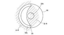
(3)−4 図1において、車両の揺動により、シート部材55が接続通路32bを直ぐに閉じない場合であっても、接続通路32bへの燃料の浸入を防ぐための構成が設けられている。すなわち、フロート51の上部に形成された防護壁52bは、車両の揺動により弁室30S内に入った燃料を接続通路32bの上流側で遮る。また、シート部材55は、接続通路32bに近接した位置で支持されているから、シート部材55が接続通路32bを開いている状態であっても、燃料が接続通路32bに入るのを遮る。図7は接続通路32bへの燃料の流出を防止する範囲を説明する説明図であり、接続通路32bを中心に上方から見た図である。接続通路32bの開口領域は、領域A−Rにて防護壁52bにより接続通路32bへの経路が遮られるとともに、領域B−Rにてシート部材55により接続通路32bへの経路が遮られ、つまり、弁室30Sから接続通路32bに向かう経路のほぼ全域にわたって燃料の流入を遮る部材が配置されているから、確実に外部への燃料の流出を防止することができる。
(3) -4 In FIG. 1, even when the
なお、この発明は上記実施例に限られるものではなく、その要旨を逸脱しない範囲において種々の態様において実施することが可能であり、例えば次のような変形も可能である。 The present invention is not limited to the above-described embodiments, and can be implemented in various modes without departing from the gist thereof. For example, the following modifications are possible.
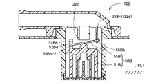
(1) 図8は第2の実施例にかかる燃料遮断弁10Bを示す断面図である。第2の実施例は、弁体機構50Bを構成するフロート51Bの上部とシート部材55Bとの係合手段に特徴を有する。円板形状のシート部材55Bの外周であって被支持端55Bbの反対側には、係合端55Bb−2が突設されている。また、防護壁52Bbには、係合穴52Bdが形成されており、この係合穴52Bdに、上記係合端55Bb−2が突入している。この構成において、フロート51Bが上昇位置にありかつシート部材55Bが閉弁しているときに、フロート51Bが下降すると係合穴52Bdに係合端55Bb−2が係合して被支持端55Bbを支点にして回動することで、シート部材55Bは、シール部32cから容易に離座する。
(1) FIG. 8 is a sectional view showing a
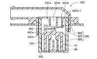
(2) 図9は第3の実施例にかかる燃料遮断弁10Cを示す断面図である。第3の実施例は、ケーシング20Cの構成に特徴を有する。ケーシング20Cは、ケーシング本体30Cと、天井壁32Cと、蓋体40Cとから構成されており、ケーシング本体30Cおよび天井壁32Cがポリアセタールにより、蓋体40Cがポリエチレンによりそれぞれ形成されている。上記ケーシング本体30Cは、側壁33Cおよび底部35Cをカップ状に一体形成している。上記天井壁32Cには、接続通路32Cbを有する上部突出部32Ca、および支持穴32Cd−1を有する弁支持部32Cdがそれぞれ形成されている。上記側壁33Cには、係合突起33Ceが形成されている。一方、蓋体40Cの下部には、支持部45Cが突設されており、支持部45Cに係合突起33Ceに係合する係合穴45Caが形成されている。
(2) FIG. 9 is a cross-sectional view showing a fuel cutoff valve 10C according to the third embodiment. The third embodiment is characterized by the configuration of the casing 20C. The casing 20C includes a
燃料遮断弁10Cを組み付けるには、ケーシング本体30C内にスプリング60、フロート51を収納する。その後に、シート部材55を組み付けた天井壁32Cの外周部にケーシング本体30Cの上端を溶着する。さらに、支持部45Cをケーシング本体30Cの上部に嵌合するとともに、支持部45Cの係合穴45Caを係合突起33Ceに係合することで蓋体40Cをケーシング20Cに組み付ける。このように天井壁32Cをケーシング本体30Cと別体に構成することにより、弁支持部32Cdの支持穴32Cd−1を容易に成形することができる。
In order to assemble the fuel cutoff valve 10C, the
(3) 上記実施例では、シート部材55は、弁支持部32dの支持穴32d−1に挿入することにより支持する構成を説明したが、これに限らず、ピンやヒンジなどの構成で回動可能に支持する構成であってもよい。
(3) In the above-described embodiment, the structure in which the
10...燃料遮断弁
10B...燃料遮断弁
10C...燃料遮断弁
20...ケーシング
20C...ケーシング
30...ケーシング本体
30C...ケーシング本体
30S...弁室
30a...下開口
32...天井壁部
32C...天井壁
32a...上部突出部
32Ca...上部突出部
32b...接続通路
32Cb...接続通路
32c...シール部
32d...弁支持部
32Cd...弁支持部
32d−1...支持穴
32Cd−1...支持穴
33...側壁
33C...側壁
33a...連通孔
33b...係合穴
33c...フランジ部
33Ce...係合突起
35...底支持板
35C...底部
35a...係合爪
35b...連通路
35b...連通孔
40...蓋体
40C...蓋体
41...蓋本体
42...管体部
42a...管体通路
42a...蓋側通路
43...フランジ
43a...環状溶着部
44...溶着面
45C...支持部
45Ca...係合穴
50...弁体機構
50B...弁体機構
51...フロート
51B...フロート
51S...浮力室
51a...ガイド突条
52...上壁部
52a...中央突部
52b...防護壁
52Bb...防護壁
52c...係合部
52Bd...係合穴
53...側壁部
55...シート部材
55B...シート部材
55a...シート本体
55b−1...爪
55Bb−2...係合端
55b...被支持端
55Bb...被支持端
55c...シート面
60...スプリング
FT...燃料タンク
FTa...タンク上壁
FTc...取付穴
DESCRIPTION OF
Claims (4)
上記燃料タンク(FT)内に連通する弁室(30S)を有するケーシング(20)と、
上記ケーシング(20)の上部に設けられ、上記弁室(30S)内と外部とを接続する接続通路(32b)と、
上記弁室(30S)内に収納され上記燃料タンク(FT)内の燃料液位に応じて昇降するフロート(51)と、上記フロート(51)の上部に配置されたシート部材(55)とを有する弁体機構(50)と、
を備え、
上記弁体機構(50)は、
上記接続通路(32b)に近接しかつケーシング(20)の内壁面に設けられ、上記シート部材(55)が上記接続通路(32b)を開閉可能であるように上記シート部材(55)の一端を支持する弁支持部(32d)を有すること、
を特徴とする燃料遮断弁。 A fuel shut-off valve that is mounted on the upper part of the fuel tank (FT) and cuts off the communication between the inside and outside of the fuel tank (FT).
A casing (20) having a valve chamber (30S) communicating with the fuel tank (FT);
A connection passage (32b) provided in an upper portion of the casing (20) and connecting the inside of the valve chamber (30S) and the outside;
A float (51) that is housed in the valve chamber (30S) and moves up and down according to the fuel level in the fuel tank (FT), and a seat member (55) that is disposed on the top of the float (51). A valve body mechanism (50) having;
With
The valve body mechanism (50)
One end of the seat member (55) is provided near the connection passage (32b) and on the inner wall surface of the casing (20) so that the seat member (55) can open and close the connection passage (32b). Having a valve support (32d) to support,
A fuel shut-off valve characterized by
上記弁体機構(50)は、上記フロート(51)の上下の動きに連動して上記シート部材(55)が上記接続通路(32b)を開閉可能に構成した燃料遮断弁。 The fuel cutoff valve according to claim 1,
The valve body mechanism (50) is a fuel cutoff valve configured such that the seat member (55) can open and close the connection passage (32b) in conjunction with the vertical movement of the float (51).
上記弁体機構(50)は、
上記フロート(51)の上部に形成された係合部(52c)を有し、該係合部(52c)は、上記シート部材(55)が上記接続通路(32b)を閉じている状態から上記フロート(51)が下降したときに、上記シート部材(55)の他端に係合して上記シート部材(55)が上記接続通路(32b)を開くように形成されている燃料遮断弁。 The fuel cutoff valve according to claim 1 or 2,
The valve body mechanism (50)
There is an engaging part (52c) formed on the upper part of the float (51), and the engaging part (52c) is in a state where the seat member (55) closes the connection passage (32b). A fuel cutoff valve formed so that when the float (51) descends, the seat member (55) is engaged with the other end of the seat member (55) to open the connection passage (32b).
上記フロート(51)の上部であって上記シート部材(55)を中心として上記弁支持部(32d)と反対側の部位に、上記弁室(30S)から上記接続通路(32b)に向かう経路を遮る防護壁(52b)を設けた燃料遮断弁。
The fuel cutoff valve according to any one of claims 1 to 3,
A path from the valve chamber (30S) to the connection passage (32b) is provided at the upper part of the float (51) and on the opposite side of the valve support (32d) with the seat member (55) as the center. A fuel cutoff valve provided with a protective wall (52b) for shielding.
Priority Applications (1)
| Application Number | Priority Date | Filing Date | Title |
|---|---|---|---|
| JP2004112203A JP2005299399A (en) | 2004-04-06 | 2004-04-06 | Fuel shut-off valve |
Applications Claiming Priority (1)
| Application Number | Priority Date | Filing Date | Title |
|---|---|---|---|
| JP2004112203A JP2005299399A (en) | 2004-04-06 | 2004-04-06 | Fuel shut-off valve |
Publications (2)
| Publication Number | Publication Date |
|---|---|
| JP2005299399A true JP2005299399A (en) | 2005-10-27 |
| JP2005299399A5 JP2005299399A5 (en) | 2006-10-26 |
Family
ID=35331272
Family Applications (1)
| Application Number | Title | Priority Date | Filing Date |
|---|---|---|---|
| JP2004112203A Withdrawn JP2005299399A (en) | 2004-04-06 | 2004-04-06 | Fuel shut-off valve |
Country Status (1)
| Country | Link |
|---|---|
| JP (1) | JP2005299399A (en) |
-
2004
- 2004-04-06 JP JP2004112203A patent/JP2005299399A/en not_active Withdrawn
Similar Documents
| Publication | Publication Date | Title |
|---|---|---|
| JP4135664B2 (en) | Fuel shut-off valve | |
| JP3506034B2 (en) | Fuel shutoff valve | |
| EP1705051B1 (en) | Low profile overfill limit device with reverse flow capability | |
| US8261763B2 (en) | Tank valve unit | |
| US5996607A (en) | Installing a fill limiting vent valve in a fuel tank | |
| JP2006009645A (en) | Fuel cutoff valve | |
| US20080251134A1 (en) | Fuel cutoff valve | |
| JP2012047169A (en) | Fuel tank valve device and fuel tank ventilation device | |
| JP4694533B2 (en) | Fuel shut-off valve | |
| JP4329769B2 (en) | Fuel shut-off valve | |
| JP5949686B2 (en) | In-tank valve unit | |
| US7963296B2 (en) | Fuel cutoff valve | |
| JP2011235772A (en) | Fuel shut-off valve | |
| JP2005299399A (en) | Fuel shut-off valve | |
| JP4305256B2 (en) | Fuel shut-off valve | |
| JP5035215B2 (en) | Fuel shut-off valve | |
| JP2010077941A (en) | Fuel shut-off valve | |
| JP4193782B2 (en) | Fuel shut-off valve | |
| JP3988671B2 (en) | Valve for fuel tank | |
| JP2009279981A (en) | Fuel shut-off valve | |
| JP2010173397A (en) | Fuel shutoff valve | |
| JP2011131710A (en) | Fuel cutoff valve | |
| JP4487915B2 (en) | Fuel shut-off valve | |
| JP2001254856A (en) | Fuel shut-off valve | |
| JP2005351293A (en) | Fuel cutoff valve |
Legal Events
| Date | Code | Title | Description |
|---|---|---|---|
| A521 | Written amendment |
Free format text: JAPANESE INTERMEDIATE CODE: A523 Effective date: 20060907 |
|
| A621 | Written request for application examination |
Effective date: 20060926 Free format text: JAPANESE INTERMEDIATE CODE: A621 |
|
| A761 | Written withdrawal of application |
Free format text: JAPANESE INTERMEDIATE CODE: A761 Effective date: 20080326 |