JP2005298884A - Method for adjusting porosity of sprayed coating and cylinder block of engine in which porosity of inner surface of cylinder bore is adjusted by this method - Google Patents
Method for adjusting porosity of sprayed coating and cylinder block of engine in which porosity of inner surface of cylinder bore is adjusted by this method Download PDFInfo
- Publication number
- JP2005298884A JP2005298884A JP2004115490A JP2004115490A JP2005298884A JP 2005298884 A JP2005298884 A JP 2005298884A JP 2004115490 A JP2004115490 A JP 2004115490A JP 2004115490 A JP2004115490 A JP 2004115490A JP 2005298884 A JP2005298884 A JP 2005298884A
- Authority
- JP
- Japan
- Prior art keywords
- porosity
- sprayed coating
- coating
- thermal spray
- sprayed
- Prior art date
- Legal status (The legal status is an assumption and is not a legal conclusion. Google has not performed a legal analysis and makes no representation as to the accuracy of the status listed.)
- Granted
Links
Images
Landscapes
- Coating By Spraying Or Casting (AREA)
Abstract
【課題】 溶射皮膜表面の気孔率変更を容易に行えるようにする。
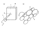
【解決手段】 溶射用金属材料の溶滴3を溶射して皮膜を形成した溶射皮膜表面1に高圧流体9を噴射し、溶射皮膜を形成する溶滴3の一部を吹き飛ばすことで、溶射皮膜表面1に微小な気孔を形成する。
【選択図】 図1PROBLEM TO BE SOLVED: To easily change the porosity of a sprayed coating surface.
SOLUTION: A thermal spray coating is formed by spraying a high pressure fluid 9 onto a sprayed coating surface 1 formed by spraying a droplet 3 of a metal material for thermal spraying to form a coating, and blowing off a part of the droplet 3 forming the sprayed coating. Micropores are formed on the surface 1.
[Selection] Figure 1
Description
本発明は、溶射用材料の溶滴を溶射して皮膜を形成した溶射皮膜表面の溶射皮膜気孔率調整方法およびこの方法によってシリンダボア内面の気孔率を調整したエンジンのシリンダブロックに関する。 The present invention relates to a method for adjusting the porosity of a sprayed coating surface on which a coating is formed by spraying droplets of a thermal spraying material, and a cylinder block of an engine in which the porosity of an inner surface of a cylinder bore is adjusted by this method.
溶射皮膜は、溶射用金属材料を溶融させ溶滴として加工表面に溶射して得るものであり、このような溶射皮膜の面性状について重要な点の一つとして、気孔率がある。気孔率とは、溶射皮膜表面における、溶射皮膜特有の溶滴相互の隙間による凹部(気孔)が占める面積率のことで、溶射工法、溶射材料、溶射皮膜表面の前加工方法によって決まる傾向がある。 The thermal spray coating is obtained by melting the thermal spraying metal material and spraying it on the processing surface as droplets. One of the important aspects of the surface properties of such a thermal spray coating is porosity. The porosity is the area ratio occupied by the recesses (pores) due to the gaps between the droplets peculiar to the thermal spray coating on the surface of the thermal spray coating, and tends to be determined by the thermal spraying method, the thermal spray material, and the pre-processing method of the thermal spray coating surface. .
例えば下記特許文献1には、溶射皮膜を形成するための前処理として、高圧水噴射ノズルを用いて溶射皮膜を形成する面を洗浄する技術が開示されている。
上記した溶射皮膜表面の気孔率を決める溶射工法、溶射材料、前加工方法の3項目が、設計要求や設備コストなどにより決まっている場合には、気孔率を変更して、例えば溶射皮膜表面の保油性や潤滑性を図りたくても容易にできないという問題がある。 If the three items of spraying method, spraying material, and pre-processing method that determine the porosity of the above-mentioned sprayed coating surface are determined by design requirements, equipment costs, etc., change the porosity, for example, There is a problem that it is not easy to achieve oil retention and lubricity.
そこで、本発明は、溶射皮膜表面の気孔率変更を容易に行えるようにすることを目的としている。 Accordingly, an object of the present invention is to make it easy to change the porosity of the surface of the sprayed coating.
本発明は、溶射用材料の溶滴を溶射して皮膜を形成した溶射皮膜表面に高圧流体を噴射し、前記溶射皮膜を形成する溶滴の一部を吹き飛ばすことで、前記溶射皮膜表面に微小な気孔を形成することを最も主要な特徴とする。 The present invention is directed to spraying a high pressure fluid onto the surface of a thermal spray coating formed by spraying a droplet of a thermal spray material, and blowing off a part of the droplet forming the thermal spray coating, thereby forming a microscopic surface on the surface of the thermal spray coating. The most important feature is the formation of open pores.
本発明によれば、溶射皮膜形成後に、溶滴の一部を吹き飛ばすことで、溶滴相互の隙間に相当する気孔の占める面積率(気孔率)を容易に変更することができる。 According to the present invention, the area ratio (porosity) occupied by the pores corresponding to the gaps between the droplets can be easily changed by blowing off a part of the droplets after forming the sprayed coating.
以下、本発明の実施の形態を図面に基づき説明する。 Hereinafter, embodiments of the present invention will be described with reference to the drawings.
図1は、本発明の一実施形態に係わる溶射皮膜気孔率調整方法を示している。図1(a)に示すワークWの溶射皮膜表面1は、図示しない溶射装置によって溶射皮膜を形成してある。この溶射皮膜表面1は、図1(b)に示すように、溶射用金属材料を溶融させた溶滴3を図示しない溶射ガンによって吹き付け、この溶滴3が扁平状となって多数重なるようにしてワーク表面に付着している。 FIG. 1 shows a thermal spray coating porosity adjusting method according to an embodiment of the present invention. The sprayed coating surface 1 of the workpiece W shown in FIG. 1A has a sprayed coating formed by a spraying device (not shown). As shown in FIG. 1B, the spray coating surface 1 is sprayed with a spray gun (not shown) by melting a metal material for spraying so that the spray droplets 3 are flattened and overlapped. Is attached to the workpiece surface.
ここで、溶射皮膜表面1の表面性状を表す指標として気孔率があるが、気孔率は、各溶滴3相互の隙間5によってできる凹部や、溶射時での溶滴3の脱落によってできる凹部の、溶射皮膜表面1にて占める面積の割合で示される。すなわち、上記した各凹部が気孔に相当し、溶射皮膜表面1の気孔が占める面積率が気孔率となる。 Here, there is a porosity as an index representing the surface property of the sprayed coating surface 1, but the porosity is a recess formed by the gap 5 between the droplets 3 or a recess formed by dropping of the droplet 3 during spraying. It is shown by the ratio of the area which occupies in the thermal spray coating surface 1. That is, each above-mentioned recessed part is equivalent to a pore, and the area ratio which the pore of the thermal spray coating surface 1 occupies becomes a porosity.
このような気孔率を適度に設定することで、例えばエンジンのシリンダボア内面などのような摺動面を溶射皮膜とした場合には、保油性に対して効果が大きく、耐圧を確保しながら、面積率を高めることにより、摺動性が高まる。 By appropriately setting such a porosity, for example, when a sliding surface such as the inner surface of a cylinder bore of an engine is used as a thermal spray coating, the effect on oil retention is great, while ensuring a pressure resistance, the area By increasing the rate, the slidability increases.
そして、本実施形態では、溶射皮膜表面1に、高圧液体噴射ガン7により、高圧流体9として例えば水や油からなる液体を噴射し、溶滴3の一部を吹き飛ばして強制的に脱落させて気孔率の調整を行う。
And in this embodiment, the liquid which consists of water or oil, for example as a high-
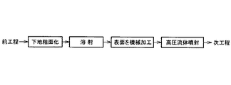
ここで、上記した高圧流体の噴射を行う前に、図2に示すような加工を行う。すなわちワークWの加工面を前工程で所定形状に加工した後、加工面に対する溶滴の付着を容易にするためにショットブラスト法などによって下地粗面化を行った上で、溶射装置によって溶射皮膜を形成して前記した溶射皮膜表面1とする。 Here, before performing the injection of the high-pressure fluid described above, processing as shown in FIG. 2 is performed. In other words, after processing the processed surface of the workpiece W into a predetermined shape in the previous process, in order to facilitate the adhesion of droplets to the processed surface, the surface is roughened by a shot blasting method, etc. To form the above-mentioned sprayed coating surface 1.
そして、この溶射皮膜表面1を機械加工して平滑にした上で、前記した高圧液体噴射ガン7により高圧流体9を溶射皮膜表面1に吹き付け、その後ワークWを次工程へ搬送する。なお、ここでの高圧流体9の噴射は、機械加工後の溶射皮膜表面1の洗浄を兼ねている。
Then, the sprayed coating surface 1 is machined and smoothed, and then the high-
また、高圧流体9の溶射皮膜表面1に対する吹き付け角度は、垂直とすることが望ましい。これは、溶射皮膜表面1に対して傾斜させた状態で噴射すると、高圧流体9の安定した慣性力が得られず、溶滴3が脱落しにくくなるからである。
Further, it is desirable that the spray angle of the high-
このように、溶射皮膜表面1に高圧流体9を吹き付けることで、溶射皮膜表面1の小さな溶滴3や大きな溶滴3の一部位を強制的に吹き飛ばすことで、溶滴3の一部を脱落させ、気孔率を調整する。この場合の気孔率の調整は、溶射工法、溶射材料、前加工方法の3項目が、設計要求や設備コストなどにより決まっている場合であっても、溶射後に適宜高圧流体9を吹き付けることで、容易に行うことができる。
In this way, by spraying the
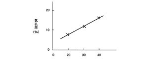
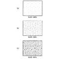
図3は、高圧流体9の吐出圧と気孔率(%)との関係を示すグラフである。これによれば、吐出圧が20MPa,30MPa,40MPaと増大するに従って気孔率が高くなっていることがわかる。図4(a),(b),(c)は、この各吐出圧によって高圧流体9を噴射した後の溶射皮膜表面1の状態を示しており、図中で黒い点が気孔を示し、吐出圧が高いほど気孔が多く、気孔率が高いことがわかる。
FIG. 3 is a graph showing the relationship between the discharge pressure of the high-
また、特に、上記したように溶射被膜表面1を機械加工して平滑にした後に、高圧流体9を吹き付けると、溶射皮膜の気孔周辺の一部が捲れ上がる現象が発生する。そこで、高圧流体噴射後に、溶射皮膜表面1を仕上げ加工することで、捲れ上がった部分を削除し、溶射皮膜表面1を平滑にすることができる。
Further, in particular, when the high-
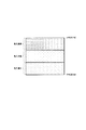
図5は、エンジンのシリンダブロックのシリンダボア内面9を溶射皮膜表面として高圧流体を吹き付けて気孔率を調整した模式図である。図5中で上部がピストンの上死点付近で、下部が下死点付近である。この場合、上死点付近を高圧流体の吐出圧を最も高くして気孔率を高め、上死点付近と下死点付近との中間部を、高圧流体の吐出圧を最も低くして気孔率を低くし、下死点付近を中間の吐出圧として気孔率を上死点付近と下死点付近との中間となるようにしている。
FIG. 5 is a schematic diagram in which the porosity is adjusted by spraying high-pressure fluid using the cylinder bore
上死点付近および下死点付近の気孔率を中間部より高くすることで、シリンダボア内面9の保油性が高まり、特に、高保油性が要求される上死点付近の気孔率を最も高くすることで、シリンダボア内面9の潤滑性が向上し、焼き付けなどの不具合を防止することができる。
By increasing the porosity near the top dead center and near the bottom dead center from the middle part, the oil retaining property of the cylinder bore
本発明によれば、前記溶射皮膜を形成する溶滴の一部を吹き飛ばした後に、溶射皮膜表面を仕上げ加工するので、溶射皮膜の気孔周辺の捲れ上がった部位を取り除いて溶射皮膜表面を平滑にすることができる。 According to the present invention, after spraying a part of the droplets forming the sprayed coating, the surface of the sprayed coating is finished, so that the area around the pores of the sprayed coating is removed to smooth the surface of the sprayed coating. can do.
溶射皮膜表面を機械加工した後に、この溶射皮膜表面に高圧の液体を噴射して溶滴の一部を吹き飛ばし、その後溶射皮膜表面を仕上げ加工するので、高圧の液体によって機械加工後の洗浄が行えるとともに、溶射皮膜の気孔周辺の捲れ上がった部位を取り除いて溶射皮膜表面を平滑にすることができる。 After machining the surface of the thermal spray coating, high pressure liquid is sprayed onto the surface of the thermal spray coating to blow off some of the droplets, and then the surface of the thermal spray coating is finished, so cleaning after machining can be performed with the high pressure liquid. At the same time, the surface of the thermal spray coating can be smoothed by removing the swelled portion around the pores of the thermal spray coating.
前記溶射皮膜表面の気孔が占める面積率を、溶射皮膜表面の部位によって変化させるので、必要に応じて気孔の占める面積率を適宜得ることができる。 Since the area ratio occupied by the pores on the surface of the thermal spray coating is changed depending on the site on the surface of the thermal spray coating, the area ratio occupied by the pores can be appropriately obtained as necessary.
前記溶射皮膜表面をエンジンのシリンダボア内面とし、このシリンダボア内面における上死点付近の前記気孔が占める面積率を他の部位より高くするので、シリンダボア内面の保油性が高まり、シリンダボア内面の潤滑性を高めることができる。 The surface of the sprayed coating is the inner surface of the cylinder bore of the engine, and the area ratio occupied by the pores near the top dead center on the inner surface of the cylinder bore is higher than that of other parts. be able to.
前記高圧流体の吐出圧を変化させることで、前記溶射皮膜表面の気孔が占める面積率を変化させるので、この気孔が占める面積率を、同一の溶射皮膜表面に対して容易に変更することができる。 By changing the discharge pressure of the high-pressure fluid, the area ratio occupied by the pores on the surface of the thermal spray coating is changed. Therefore, the area ratio occupied by the pores can be easily changed with respect to the same thermal spray coating surface. .
1 溶射皮膜表面
3 溶滴
5 溶滴相互の隙間(気孔)
9 シリンダボア内面
1 Sprayed coating surface 3 Droplet 5 Gap between droplets (pores)
9 Cylinder bore inner surface
Claims (7)
Priority Applications (1)
| Application Number | Priority Date | Filing Date | Title |
|---|---|---|---|
| JP2004115490A JP4561153B2 (en) | 2004-04-09 | 2004-04-09 | Method for adjusting porosity of sprayed coating and cylinder block of engine in which porosity of inner surface of cylinder bore is adjusted by this method |
Applications Claiming Priority (1)
| Application Number | Priority Date | Filing Date | Title |
|---|---|---|---|
| JP2004115490A JP4561153B2 (en) | 2004-04-09 | 2004-04-09 | Method for adjusting porosity of sprayed coating and cylinder block of engine in which porosity of inner surface of cylinder bore is adjusted by this method |
Publications (2)
| Publication Number | Publication Date |
|---|---|
| JP2005298884A true JP2005298884A (en) | 2005-10-27 |
| JP4561153B2 JP4561153B2 (en) | 2010-10-13 |
Family
ID=35330796
Family Applications (1)
| Application Number | Title | Priority Date | Filing Date |
|---|---|---|---|
| JP2004115490A Expired - Lifetime JP4561153B2 (en) | 2004-04-09 | 2004-04-09 | Method for adjusting porosity of sprayed coating and cylinder block of engine in which porosity of inner surface of cylinder bore is adjusted by this method |
Country Status (1)
| Country | Link |
|---|---|
| JP (1) | JP4561153B2 (en) |
Cited By (4)
| Publication number | Priority date | Publication date | Assignee | Title |
|---|---|---|---|---|
| WO2012160654A1 (en) * | 2011-05-24 | 2012-11-29 | トヨタ自動車 株式会社 | Method for modifying surface of aluminum alloy cylinder block |
| JP2016169725A (en) * | 2015-03-09 | 2016-09-23 | トヨタ自動車株式会社 | Thermal spray cylinder block manufacturing method |
| EP3081666A1 (en) * | 2015-04-16 | 2016-10-19 | Toyota Jidosha Kabushiki Kaisha | Method for producing clycinder block |
| CN119838795A (en) * | 2025-03-24 | 2025-04-18 | 山西凯得森建筑科技有限公司 | Cleaning device for powder spraying room |
Citations (10)
| Publication number | Priority date | Publication date | Assignee | Title |
|---|---|---|---|---|
| JPS5334635A (en) * | 1976-09-13 | 1978-03-31 | Toyota Motor Co Ltd | Surface treatment method of light alloy cylinder |
| JPS55164745A (en) * | 1979-05-22 | 1980-12-22 | Nippon Piston Ring Co Ltd | Cylinder and cylinder liner |
| JPS57151043A (en) * | 1981-03-13 | 1982-09-18 | Nippon Piston Ring Co Ltd | Cylinder for internal combustion engine |
| JPS62107100A (en) * | 1985-11-01 | 1987-05-18 | Toyota Motor Corp | Method for etching bore surface of cylinder block |
| JPS62256999A (en) * | 1986-04-28 | 1987-11-09 | Mazda Motor Corp | Production of sliding contact member having superior wear resistance |
| JPH08246944A (en) * | 1995-03-08 | 1996-09-24 | Suzuki Motor Corp | Cylinder of internal combustion engine and manufacturing method thereof |
| JPH09158777A (en) * | 1995-12-11 | 1997-06-17 | Suzuki Motor Corp | Non-upright cylinder engine cylinder and method of manufacturing the same |
| WO2001032352A1 (en) * | 1999-11-04 | 2001-05-10 | Toyota Jidosha Kabushiki Kaisha | Surface pit forming method and member with surface pit |
| JP2001214251A (en) * | 1999-11-24 | 2001-08-07 | General Electric Co <Ge> | Thermal insulation coating method |
| JP2003117502A (en) * | 2001-10-12 | 2003-04-22 | Toyota Motor Corp | Method for treating cylinder bore surface and method for treating perforated side wall surface |
-
2004
- 2004-04-09 JP JP2004115490A patent/JP4561153B2/en not_active Expired - Lifetime
Patent Citations (10)
| Publication number | Priority date | Publication date | Assignee | Title |
|---|---|---|---|---|
| JPS5334635A (en) * | 1976-09-13 | 1978-03-31 | Toyota Motor Co Ltd | Surface treatment method of light alloy cylinder |
| JPS55164745A (en) * | 1979-05-22 | 1980-12-22 | Nippon Piston Ring Co Ltd | Cylinder and cylinder liner |
| JPS57151043A (en) * | 1981-03-13 | 1982-09-18 | Nippon Piston Ring Co Ltd | Cylinder for internal combustion engine |
| JPS62107100A (en) * | 1985-11-01 | 1987-05-18 | Toyota Motor Corp | Method for etching bore surface of cylinder block |
| JPS62256999A (en) * | 1986-04-28 | 1987-11-09 | Mazda Motor Corp | Production of sliding contact member having superior wear resistance |
| JPH08246944A (en) * | 1995-03-08 | 1996-09-24 | Suzuki Motor Corp | Cylinder of internal combustion engine and manufacturing method thereof |
| JPH09158777A (en) * | 1995-12-11 | 1997-06-17 | Suzuki Motor Corp | Non-upright cylinder engine cylinder and method of manufacturing the same |
| WO2001032352A1 (en) * | 1999-11-04 | 2001-05-10 | Toyota Jidosha Kabushiki Kaisha | Surface pit forming method and member with surface pit |
| JP2001214251A (en) * | 1999-11-24 | 2001-08-07 | General Electric Co <Ge> | Thermal insulation coating method |
| JP2003117502A (en) * | 2001-10-12 | 2003-04-22 | Toyota Motor Corp | Method for treating cylinder bore surface and method for treating perforated side wall surface |
Cited By (5)
| Publication number | Priority date | Publication date | Assignee | Title |
|---|---|---|---|---|
| WO2012160654A1 (en) * | 2011-05-24 | 2012-11-29 | トヨタ自動車 株式会社 | Method for modifying surface of aluminum alloy cylinder block |
| JP2016169725A (en) * | 2015-03-09 | 2016-09-23 | トヨタ自動車株式会社 | Thermal spray cylinder block manufacturing method |
| EP3081666A1 (en) * | 2015-04-16 | 2016-10-19 | Toyota Jidosha Kabushiki Kaisha | Method for producing clycinder block |
| US10259146B2 (en) | 2015-04-16 | 2019-04-16 | Toyota Jidosha Kabushiki Kaisha | Producing method for cylinder block |
| CN119838795A (en) * | 2025-03-24 | 2025-04-18 | 山西凯得森建筑科技有限公司 | Cleaning device for powder spraying room |
Also Published As
| Publication number | Publication date |
|---|---|
| JP4561153B2 (en) | 2010-10-13 |
Similar Documents
| Publication | Publication Date | Title |
|---|---|---|
| US20130284140A1 (en) | Method for roughening and coating a surface | |
| JP3780840B2 (en) | Pre-spraying shape of the inner surface of a cylinder | |
| US10746128B2 (en) | Cylinder bore having variable coating | |
| RU2483139C1 (en) | Cylinder block and coat gas-thermal evaporation | |
| CN105555987A (en) | Method for machining a cylinder wall of an internal combustion engine | |
| CN101379212A (en) | Surface conditioning for thermal spray layers | |
| JP2005307857A (en) | Cylinder block and manufacturing method thereof | |
| JP4561153B2 (en) | Method for adjusting porosity of sprayed coating and cylinder block of engine in which porosity of inner surface of cylinder bore is adjusted by this method | |
| JP6370394B2 (en) | Piston without closed cooling chamber for an internal combustion engine having at least one cooling oil nozzle per cylinder and method for cooling the piston | |
| CN109234665B (en) | Selective surface texturing for cylinder liners | |
| Nastic et al. | A numerical study of thermal shrinkage influence on the impact dynamics of alumina droplets thermally sprayed on flat, grit-blasted and laser treated surfaces | |
| DE102009051262A1 (en) | Method for producing a thermally sprayed cylinder barrel for the combustion engines, comprises applying a coating on an inner side of a cylinder by means of a thermal spraying | |
| JP5365723B2 (en) | Manufacturing method of piercing and rolling plug | |
| JP2009195935A (en) | Plunger sleeve and manufacturing method therefor | |
| CA2986718C (en) | Method of honing high-porosity clyinder liners | |
| JP2005171274A (en) | Method for forming sprayed coating and sliding member | |
| KR102018429B1 (en) | Method for coating a cylinder of an internal combustion engine, and cylinder for an internal combustion engine | |
| JP5789076B2 (en) | Cylinder bore inner surface repair method and cylinder bore inner surface repair device | |
| JP3838344B2 (en) | Cylinder bore surface processing method and perforated sidewall surface processing method | |
| KR20110105547A (en) | Molybdenum Coated Marine Engine Piston Skirt | |
| JP2007521977A (en) | Method of processing the workpiece surface | |
| KR102738818B1 (en) | mold device for manufacturing of billets | |
| JP2010013993A (en) | Method for machining cylinder bore surface | |
| Radek et al. | Production of heterogeneous surfaces by ESD and LBM | |
| DE102008052342A1 (en) | Track layer processing method for internal combustion engine, involves processing wear protection layer i.e. tribological layer, by rubbing and using tool with geometrically defined cutting edge for mechanical re-processing |
Legal Events
| Date | Code | Title | Description |
|---|---|---|---|
| A621 | Written request for application examination |
Free format text: JAPANESE INTERMEDIATE CODE: A621 Effective date: 20070226 |
|
| A977 | Report on retrieval |
Free format text: JAPANESE INTERMEDIATE CODE: A971007 Effective date: 20090910 |
|
| A131 | Notification of reasons for refusal |
Free format text: JAPANESE INTERMEDIATE CODE: A131 Effective date: 20090915 |
|
| A521 | Request for written amendment filed |
Free format text: JAPANESE INTERMEDIATE CODE: A523 Effective date: 20091106 |
|
| A131 | Notification of reasons for refusal |
Free format text: JAPANESE INTERMEDIATE CODE: A131 Effective date: 20100427 |
|
| A521 | Request for written amendment filed |
Free format text: JAPANESE INTERMEDIATE CODE: A523 Effective date: 20100611 |
|
| TRDD | Decision of grant or rejection written | ||
| A01 | Written decision to grant a patent or to grant a registration (utility model) |
Free format text: JAPANESE INTERMEDIATE CODE: A01 Effective date: 20100706 |
|
| A01 | Written decision to grant a patent or to grant a registration (utility model) |
Free format text: JAPANESE INTERMEDIATE CODE: A01 |
|
| A61 | First payment of annual fees (during grant procedure) |
Free format text: JAPANESE INTERMEDIATE CODE: A61 Effective date: 20100719 |
|
| FPAY | Renewal fee payment (event date is renewal date of database) |
Free format text: PAYMENT UNTIL: 20130806 Year of fee payment: 3 |
|
| R150 | Certificate of patent or registration of utility model |
Ref document number: 4561153 Country of ref document: JP Free format text: JAPANESE INTERMEDIATE CODE: R150 Free format text: JAPANESE INTERMEDIATE CODE: R150 |
|
| FPAY | Renewal fee payment (event date is renewal date of database) |
Free format text: PAYMENT UNTIL: 20140806 Year of fee payment: 4 |
|
| EXPY | Cancellation because of completion of term |