JP2005298092A - Image forming device - Google Patents
Image forming device Download PDFInfo
- Publication number
- JP2005298092A JP2005298092A JP2004113988A JP2004113988A JP2005298092A JP 2005298092 A JP2005298092 A JP 2005298092A JP 2004113988 A JP2004113988 A JP 2004113988A JP 2004113988 A JP2004113988 A JP 2004113988A JP 2005298092 A JP2005298092 A JP 2005298092A
- Authority
- JP
- Japan
- Prior art keywords
- sheet
- image forming
- sheet supply
- main body
- opening
- Prior art date
- Legal status (The legal status is an assumption and is not a legal conclusion. Google has not performed a legal analysis and makes no representation as to the accuracy of the status listed.)
- Pending
Links
- 229920006324 polyoxymethylene Polymers 0.000 claims description 4
- 229930182556 Polyacetal Natural products 0.000 claims description 3
- 239000011347 resin Substances 0.000 claims description 3
- 229920005989 resin Polymers 0.000 claims description 3
- 230000015572 biosynthetic process Effects 0.000 description 4
- 239000002184 metal Substances 0.000 description 4
- 238000005096 rolling process Methods 0.000 description 3
- 210000000078 claw Anatomy 0.000 description 2
- 230000007246 mechanism Effects 0.000 description 2
- 238000005452 bending Methods 0.000 description 1
- 230000008901 benefit Effects 0.000 description 1
- 238000004140 cleaning Methods 0.000 description 1
- 229920006351 engineering plastic Polymers 0.000 description 1
- 239000011521 glass Substances 0.000 description 1
- 230000001678 irradiating effect Effects 0.000 description 1
- 238000004519 manufacturing process Methods 0.000 description 1
- 238000012986 modification Methods 0.000 description 1
- 230000004048 modification Effects 0.000 description 1
- 230000003287 optical effect Effects 0.000 description 1
- 238000003825 pressing Methods 0.000 description 1
- 238000000926 separation method Methods 0.000 description 1
- 238000003892 spreading Methods 0.000 description 1
- 230000007480 spreading Effects 0.000 description 1
- 238000011144 upstream manufacturing Methods 0.000 description 1
Images

Landscapes
- Paper Feeding For Electrophotography (AREA)
- Sheets, Magazines, And Separation Thereof (AREA)
Abstract
Description
本発明は、複写機やプリンタといったように、シートに画像を形成する画像形成装置に関し、特に、シートの供給元として本体装置内のシートカセットに加え、本体装置の外部にシート供給装置を備えた画像形成装置に関する。 The present invention relates to an image forming apparatus that forms an image on a sheet, such as a copying machine or a printer, and more particularly, as a sheet supply source, a sheet supply device is provided outside the main body device in addition to a sheet cassette in the main body device. The present invention relates to an image forming apparatus.
従来一般の画像形成装置は、感光体ドラム、帯電器、露光器、現像器、転写器、定着器等で構成される画像形成部を搭載した本体装置に、シートを収納したシートカセットが正面から出し入れ自在に設けられて成り、シートカセットから画像形成部へシートが供給され、このシートに対して画像形成部による画像形成が行われる。この本体装置単体のみから成る画像形成装置では、シートカセットへ収納されるシート枚数に制限がある(一般には最高500枚程度)ため、一度に大量のシートに画像形成を行う場合には、途中で新たなシートをシートカセットへ補充する必要があり不便である。このような不都合に対処するために、数千枚の大量のシートを収納できる別体のシート供給装置を本体装置に取り付け、このシート供給装置から本体装置内の画像形成部へシートを供給するようにしたものが知られている(例えば、特許文献1参照)。 Conventional general image forming apparatuses have a sheet cassette containing sheets from the front in a main body device equipped with an image forming unit composed of a photosensitive drum, a charger, an exposure device, a developing device, a transfer device, a fixing device, and the like. The sheet is provided so that it can be taken in and out, and a sheet is supplied from the sheet cassette to the image forming unit, and an image is formed on the sheet by the image forming unit. In the image forming apparatus composed of only the main body unit, the number of sheets stored in the sheet cassette is limited (generally, about 500 at most). Therefore, when forming an image on a large number of sheets at one time, It is inconvenient because a new cassette needs to be replenished to the sheet cassette. In order to cope with such inconvenience, a separate sheet feeding apparatus capable of storing a large number of thousands of sheets is attached to the main body apparatus, and the sheets are fed from the sheet feeding apparatus to the image forming unit in the main body apparatus. What was made into is known (for example, refer patent document 1).
具体的には、このようなシート供給装置を備えた画像形成装置においては、本体装置の下部にシートカセットが、その上部に画像形成部がそれぞれ配設されていて、シートカセットから画像形成部へのシート供給経路が本体装置の一側面の内部近傍に沿って設けられている。この本体装置における上記側面にシート供給装置が取り付けられる。また、上記シート供給経路にはシートが詰まってしまうことがあるため、このジャムシートを取り除くジャム処理の作業性を踏まえ、以下に示す工夫が施されている。 Specifically, in an image forming apparatus provided with such a sheet supply device, a sheet cassette is disposed at the lower part of the main body apparatus, and an image forming unit is disposed at the upper part thereof, from the sheet cassette to the image forming part. Is provided along the vicinity of the inside of one side surface of the main body apparatus. A sheet feeding device is attached to the side surface of the main body device. Further, since the sheet may be jammed in the sheet supply path, the following measures are taken in consideration of the workability of the jam processing for removing the jammed sheet.
本体装置に取り付けられたシート供給装置は、後述するように、本体装置の上記側面に対して接離可能になっている。本体装置の上記側面には、奥側を支軸に正面から開閉可能な開閉カバーが設けられている。この開閉カバーは、閉じたときに上記シート供給経路の一部を構成し、開いたときに上記シート供給経路を開放するものである。ジャム処理の際は、先ずシート供給装置を本体装置から離間させ、その後開閉カバーを開き、上記シート供給経路よりジャムシートを取り除く。 As will be described later, the sheet supply device attached to the main body device can be brought into contact with and separated from the side surface of the main body device. An opening / closing cover that can be opened and closed from the front is provided on the side surface of the main unit with the back side as a support shaft. The open / close cover constitutes a part of the sheet supply path when closed, and opens the sheet supply path when opened. In the jam processing, first, the sheet supply device is separated from the main body device, and then the opening / closing cover is opened, and the jammed sheet is removed from the sheet supply path.
ここで開閉カバーには、これに沿って金属製の水平軸が固定され、シート供給装置にはその水平軸に対応する位置に、操作によって回動する金属製のフックが設けられている。シート供給装置は、閉じた開閉カバーにおける水平軸にフックが引掛けられることで、本体装置の上記側面に接した状態に維持され、この状態でシートカセットやシート供給装置からシートが供給され画像形成が行われる。一方この状態から、操作によってフックが回動して水平軸から外れることで、シート供給装置の移動規制が解除され、そのままシート供給装置を本体装置から離間させジャム処理を行う。
ところで、シート供給装置の重量は、それ自体の自重に加え大量のシートの重量をも含むことから、必然的に重くなる。そうすると、閉じた開閉カバーにおける固定の水平軸には、フックを介してそのシート供給装置の重量が負荷されるため、奥側の支軸のみで支えられた開閉カバーはその支軸を支点に歪んでしまうおそれがある。この歪みは、開閉カバーにより構成される上記シート供給経路の変形をもたらし、そのシート供給経路でのシートの円滑な搬送を損ねる要因となる。 By the way, the weight of the sheet feeding apparatus inevitably increases because it includes the weight of a large number of sheets in addition to its own weight. Then, since the weight of the sheet feeding device is applied to the fixed horizontal shaft in the closed open / close cover via the hook, the open / close cover supported only by the back-side support shaft is distorted around the support shaft. There is a risk of it. This distortion causes deformation of the sheet supply path constituted by the opening / closing cover, and becomes a factor that impairs smooth conveyance of the sheet in the sheet supply path.
そこで本発明は、上記の問題に鑑みてなされたものであり、本体装置内のシート供給経路に影響を及ぼすことなくシート供給装置を備えた画像形成装置を提供することを目的とするものである。 SUMMARY An advantage of some aspects of the invention is that it provides an image forming apparatus including a sheet supply device without affecting the sheet supply path in the main body device. .
上記目的を達成するため、本発明は、シートを収納したシートカセット、及び供給されたシートに画像を形成する画像形成部を上方に向けて順に備え、シートカセットから画像形成部へのシート供給経路を一側面の内部近傍に沿って有する本体装置と、大量のシートを収納して本体装置の前記側面に取り付けられ、本体装置内の画像形成部へシートを供給するシート供給装置と、より成る画像形成装置において、本体装置の前記側面には、シート供給装置が離接可能に取り付けられるとともに、前記シート供給経路の一部を構成しつつ奥側を支軸に開閉可能で、シート供給装置を離間させて開いたときに前記シート供給経路を開放する開閉カバーが設けられており、開閉カバーには、これに沿って水平軸が固定され、シート供給装置には、閉じた開閉カバーの前記水平軸に引掛けられてシート供給装置を本体装置の前記側面に接した状態に保持するフックが設けられ、本体装置には、閉じた開閉カバーの前記水平軸を受け入れて支持する支持部材が固定されている。 In order to achieve the above object, the present invention includes a sheet cassette that stores sheets and an image forming unit that forms an image on the supplied sheet in order upward, and a sheet supply path from the sheet cassette to the image forming unit. And a sheet supply device that accommodates a large number of sheets and is attached to the side surface of the main body device and supplies the sheet to an image forming unit in the main body device. In the forming apparatus, a sheet supply device is detachably attached to the side surface of the main body device, and the back side can be opened and closed with a support shaft while forming a part of the sheet supply path. An open / close cover is provided to open the sheet supply path when opened, and a horizontal axis is fixed along the open / close cover, and the open / close cover is closed to the sheet supply device. A hook is provided that is hooked to the horizontal shaft of the open / close cover to hold the sheet supply device in contact with the side surface of the main body device. The main body device receives and supports the horizontal shaft of the closed open / close cover. A supporting member is fixed.
これにより、閉じた開閉カバーは、奥側の支軸による支持に加え、これに固定の水平軸が本体装置に固定の支持部材によって支持されるため、例えその水平軸にフックを介してシート供給装置の重量が負荷されても、開閉カバーに歪みは生じない。従って、開閉カバーにより構成されるシート供給経路の形態は継続的に安定する。 As a result, the closed opening / closing cover is supported by the support shaft on the back side, and the fixed horizontal shaft is supported by the support member fixed to the main body device. For example, the sheet is supplied to the horizontal shaft via the hook. Even if the weight of the device is loaded, the opening / closing cover is not distorted. Therefore, the form of the sheet supply path constituted by the opening / closing cover is continuously stabilized.
ここで、実用的には、前記支持部材がポリアセタール樹脂の成型品であることが好ましい。 Here, practically, the support member is preferably a molded product of polyacetal resin.
本発明の画像形成装置によれば、本体装置にこれとは別体のシート供給装置を備えていても、本体装置内におけるシート供給経路の形態が継続的に安定するため、そのシート供給経路でのシートの円滑な搬送が継続して行える。 According to the image forming apparatus of the present invention, even if the main body apparatus includes a separate sheet supply apparatus, the form of the sheet supply path in the main apparatus is continuously stabilized. Smooth conveyance of the sheet can be continued.
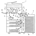
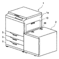
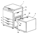
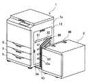
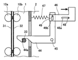
以下に、本発明の画像形成装置の一実施形態について図面を参照しながら詳述する。図1は本発明の一実施形態である画像形成装置の正面視の断面図、図2〜図4はそれぞれその画像形成装置の一状況を示す斜視図であって、図2は画像形成の際の状況を示し、図3はジャム処理に際しシート供給装置を離間させた状況を示し、図4はその後開閉カバーを開いた状況を示す。図5〜図7はそれぞれその画像形成装置の一状況を示す正面視の要部断面図であって、図5は画像形成の際の状況を示し、図6はジャム処理に際しシート供給装置を離間させた状況を示し、図7はその後開閉カバーを開いた状況を示す。なお、これらの図中で同じ名称で同じ機能を果たす部分には同一の符号を付している。 Hereinafter, an image forming apparatus according to an embodiment of the present invention will be described in detail with reference to the drawings. FIG. 1 is a front sectional view of an image forming apparatus according to an embodiment of the present invention. FIGS. 2 to 4 are perspective views showing a situation of the image forming apparatus. FIG. FIG. 3 shows a situation where the sheet supply device is separated during the jam processing, and FIG. 4 shows a situation where the opening / closing cover is opened thereafter. FIGS. 5 to 7 are cross-sectional views of the main part showing the situation of the image forming apparatus, respectively. FIG. 5 shows the situation at the time of image formation, and FIG. 6 shows the separation of the sheet feeding apparatus at the time of jam processing. FIG. 7 shows a state in which the opening / closing cover is opened thereafter. In these drawings, parts having the same names and performing the same functions are denoted by the same reference numerals.
画像形成装置は、大きくは本体装置1と、シート供給装置2とより構成される。なお本実施形態では、画像形成装置としてその代表格である複写機を例に挙げて説明する。本体装置1上には、原稿を露光走査してその原稿画像を読み取るためのコンタクトガラスや光源ランプや光学系やCCD等より成る原稿読取部3を備え、その上には、原稿押え機能を果たす自動原稿送り装置(ADF)4が取り付けられている。
The image forming apparatus includes a
また、本体装置1には、その下部に、複数段(図1では3段)のシートカセット5がそれぞれ正面側から出し入れ自在に設けられている。その上部には、両面印刷の際にシートを表裏反転させるためのシート反転部6、シートに画像形成するための画像形成部7が、上方に向けてこの順に配設されている。各シートカセット5には、シートが収納されており、このシートを取り上げるピックアップローラ8、各ピックアップローラ8からのシートの重送を防止して1枚ずつ送り出す対より成る給紙・捌きローラ9が配設されている。また、本体装置1の一側面(図1では右側面1a)の内部近傍には、各給紙・捌きローラ9から送り出されたシートを画像形成部7へ導くための、その右側面1aに沿ってこれとほぼ平行に立ち上がるシート供給経路が設けられ、このシート供給経路の適所にはシートを送る送りローラ対10が配設されている。
Further, the
更に、最下流の送りローラ対10からのシートを受け取って画像形成部7へ送り出すレジストローラ対12が配設されている。レジストローラ対12は、搬送方向に対してのシートの曲がりを矯正(スキュー補正)しつつ、画像形成部7に対して適正なタイミングでシートを送り出す。
Further, a
なお、本体装置1の右側面1aには、可倒式の手差しトレイ13が設けられていて、この手差しトレイ13からのシートは、上記の各種ローラとは別個のピックアップローラ14、対より成る給紙・捌きローラ15によって、直接最下流の送りローラ対10へ向けて供給される。また、手差しトレイ13の下方における本体装置1の右側面1aには、詳細は後述するシート供給装置2が取り付けられていて、このシート供給装置2からのシートは、直接最下流の送りローラ対10の1つ上流の送りローラ対10へ向けて供給される。
In addition, a retractable
続く画像形成部7は、像担持体である感光体ドラム16、この感光体ドラム16の表面を均一に帯電させる帯電器17、帯電された感光体ドラム16上に原稿読取部3で読み取った原稿の画像データに基づく光を照射して静電潜像を形成する露光器18、感光体ドラム16上の静電潜像にトナーを付着させトナー像を形成する現像器19、レジストローラ対12より送り出されたシートに感光体ドラム16上のトナー像を転写させる転写器20、転写後に感光体ドラム16上に残存するトナーを除去するクリーニング器21、感光体ドラム16の表面を均一に除電する除電器22、シートに転写されたトナー像を加圧・加熱して定着させ定着器23等から構成される。
Subsequently, the image forming unit 7 includes a
この画像形成部7を経て画像が形成されたシートは、分岐爪24によって排出ローラ対25へ向けて導かれ、本体装置1の左側面1bに設けられた排出シートトレイ26上へ排出される。一方、両面印刷の際には、分岐爪24によってシート反転部6へ導かれ、ここで表裏が反転された後、再び上記シート供給経路の中段へ供給され画像形成部7を経る。
The sheet on which the image is formed through the image forming unit 7 is guided toward the
シート供給装置2は、大量のシートを収納しており、このシートを本体装置1の画像形成部7へ送り出すためのピックアップローラ40、対より成る給紙・捌きローラ41、排出ローラ対42等を備える。
The
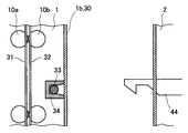
続いて、本体装置1内の上記シート供給経路でのジャム処理に対しての機構について、説明する。先ずシート供給装置2は、本体装置1の右側面1aに対して取り付けられているものの、完全に固定されているわけではなく、本体装置1の下端に連結されたレール43に案内されながら離接可能になっている。一方、本体装置1の右側面1aには、奥側を支軸に正面から開閉可能な開閉カバー30が設けられている。この開閉カバー30は、上記シート供給経路の構成要素である内側ガイド板31、外側ガイド板32、送りローラ対10(駆動ローラ10a及び従動ローラ10b)のうちの外側ガイド板32及び従動ローラ10bを備えており、閉じたときに上記シート供給経路の一部を構成し、開いたときに上記シート供給経路を開放するものである。ジャム処理の際は、先ずシート供給装置2を本体装置1から離間させて、本体装置1の右側面1a(開閉カバー30)とシート供給装置2とに間に空間を確保し、その後その空間内で開閉カバー30を開き、上記シート供給経路よりジャムシートを取り除く。
Next, a mechanism for jam processing in the sheet supply path in the
ここで開閉カバー30には、開閉カバー30そのものと外側ガイド板32との間に金属製の水平軸33が固定され、その水平軸33の一部が外部へ向けて現れるよう開口30aが2箇所に形成されている。他方シート供給装置2には、その開口30aに対応する位置に、操作によって回動する金属製のフック44が設けられている。シート供給装置2は、閉じた開閉カバー2における水平軸33に開口30aを通じてフック44が引掛けられることで、本体装置1の右側面1aに接した状態に維持され、この状態でシートカセット5やシート供給装置2からシートが供給され画像形成が行われる。一方この状態から、操作によってフック44が回動して水平軸33から外れることで、シート供給装置2の移動規制が解除され、そのままシート供給装置2を本体装置1から離間させジャム処理を行う。
Here, the opening /
更に本実施形態では、本体装置1には、閉じた開閉カバー30の水平軸33における正面側の端部、すなわち開閉用の支軸から離れた側の端部を受け入れて支持する支持部材34が固定されている。この支持部材34は、断面がコの字状で、その間に水平軸33を受け入れて水平軸33の上下移動を拘束すると同時に、閉じた開閉カバー30の上下移動も規制するものである。但し、支持部材34には、水平軸33に対しての耐磨耗性や適度な弾性を有しつつ高い機械的特性(引張りや曲げ強さ)が要求されることから、製作の容易性も踏まえ、高性能エンジニアリングプラスチック、例えばポリアセタール樹脂(POM)の成型品が好適である。
Further, in the present embodiment, the
このような構成にすると、閉じた開閉カバー30は、奥側の支軸による支持に加え、これに固定の水平軸33が本体装置1に固定の支持部材34によって支持されるため、例えその水平軸33にフック44を介してシート供給装置2の重量が負荷されても、開閉カバー30に歪みは生じない。従って、開閉カバー30により構成されるシート供給経路の形態は継続的に安定するため、そのシート供給経路でのシートの円滑な搬送が継続して行える。
With such a configuration, the closed opening /
なおここで、シート供給装置2に設けられたフック44の回動機構の一例について、図5を参照しながら説明しておく。フック44は、その引掛け部44aとは反対の端がシート供給装置2そのものに固定のピン45で軸支されている。また、シート供給装置2には、使用者によって操作される操作レバー46が水平方向(本体装置1に対してのシート供給装置2の接離方向)にスライド可能に設けられている。この操作レバー46は、シート供給装置2そのものに一端が固定の引張りコイルバネ47により、本体装置1に対してのシート供給装置2の接する方向に向けて付勢され、併せて、操作レバー46に形成されたスライド案内用溝46aと、シート供給装置2そのものに固定のスライド案内用ピン48と、の係合により、スライド移動が案内されるとともに、その移動の両端が規定されている。そして、フック44に固定の回動案内用ピン49が、操作レバー46に形成された回動案内用溝46bに係合している。
Here, an example of a rotation mechanism of the
このような構成のもと、使用者の操作により、本体装置1に対してのシート供給装置2の離間する方向に操作レバー46が押し込まれることで、引張りコイルバネ47の付勢力に抗して移動されると、これと同時にフック44がピン45を支軸に回動してその引掛け部44aが上昇する。これにより、フック44の引掛け部44aが開閉カバー30の水平軸33に引掛けられた状態から外れた状態になる。また、使用者による押し込み操作が解除されると、操作レバー46及びフック44は引張りコイルバネ47の付勢力で自動的に戻るようになる。
Under such a configuration, the
その他本発明は上記の実施形態に限定されず、本発明の趣旨を逸脱しない範囲で、種々の変更が可能である。 In addition, the present invention is not limited to the above-described embodiment, and various modifications can be made without departing from the spirit of the present invention.
本発明は、シートの供給元として本体装置内のシートカセットに加え、本体装置の外部にシート供給装置を備えた画像形成装置に有用である。 The present invention is useful for an image forming apparatus provided with a sheet supply device outside a main body apparatus in addition to a sheet cassette in the main body apparatus as a sheet supply source.
1 本体装置
2 シート供給装置
5 シートカセット
7 画像形成部
10 送りローラ対
10a 駆動ローラ
10b 従動ローラ
30 開閉カバー
31 内側ガイド板
32 外側ガイド板
33 水平軸
34 支持部材
44 フック
DESCRIPTION OF
Claims (2)
本体装置の前記側面には、シート供給装置が離接可能に取り付けられるとともに、前記シート供給経路の一部を構成しつつ奥側を支軸に開閉可能で、シート供給装置を離間させて開いたときに前記シート供給経路を開放する開閉カバーが設けられており、
開閉カバーには、これに沿って水平軸が固定され、シート供給装置には、閉じた開閉カバーの前記水平軸に引掛けられてシート供給装置を本体装置の前記側面に接した状態に保持するフックが設けられ、本体装置には、閉じた開閉カバーの前記水平軸を受け入れて支持する支持部材が固定されていることを特徴とする画像形成装置。 A sheet cassette that stores sheets and an image forming unit that forms an image on the supplied sheet in an upward direction in order, and a body that has a sheet supply path from the sheet cassette to the image forming unit along the inside of one side surface In an image forming apparatus comprising: an apparatus; and a sheet supply apparatus that stores a large number of sheets and is attached to the side surface of the main body apparatus and supplies the sheet to an image forming unit in the main body apparatus.
A sheet supply device is detachably attached to the side surface of the main unit, and the back side can be opened and closed with a support shaft while forming a part of the sheet supply path, and the sheet supply device is opened apart. An opening / closing cover that opens the sheet supply path is sometimes provided,
A horizontal shaft is fixed along the opening / closing cover, and the sheet supply device is hooked on the horizontal shaft of the closed opening / closing cover to hold the sheet supply device in contact with the side surface of the main body device. An image forming apparatus, wherein a hook is provided, and a support member that receives and supports the horizontal axis of a closed opening / closing cover is fixed to the main body device.
Priority Applications (1)
| Application Number | Priority Date | Filing Date | Title |
|---|---|---|---|
| JP2004113988A JP2005298092A (en) | 2004-04-08 | 2004-04-08 | Image forming device |
Applications Claiming Priority (1)
| Application Number | Priority Date | Filing Date | Title |
|---|---|---|---|
| JP2004113988A JP2005298092A (en) | 2004-04-08 | 2004-04-08 | Image forming device |
Publications (1)
| Publication Number | Publication Date |
|---|---|
| JP2005298092A true JP2005298092A (en) | 2005-10-27 |
Family
ID=35330110
Family Applications (1)
| Application Number | Title | Priority Date | Filing Date |
|---|---|---|---|
| JP2004113988A Pending JP2005298092A (en) | 2004-04-08 | 2004-04-08 | Image forming device |
Country Status (1)
| Country | Link |
|---|---|
| JP (1) | JP2005298092A (en) |
Cited By (1)
| Publication number | Priority date | Publication date | Assignee | Title |
|---|---|---|---|---|
| JP2019043699A (en) * | 2017-08-30 | 2019-03-22 | キヤノンファインテックニスカ株式会社 | Feeding device and image forming system |
-
2004
- 2004-04-08 JP JP2004113988A patent/JP2005298092A/en active Pending
Cited By (1)
| Publication number | Priority date | Publication date | Assignee | Title |
|---|---|---|---|---|
| JP2019043699A (en) * | 2017-08-30 | 2019-03-22 | キヤノンファインテックニスカ株式会社 | Feeding device and image forming system |
Similar Documents
| Publication | Publication Date | Title |
|---|---|---|
| JP5034609B2 (en) | Image forming apparatus | |
| CN104284044B (en) | Hinge, image read-out and image processing system with the Hinge | |
| US10551791B2 (en) | Image forming apparatus having mountable and demountable photosensitive member cartridge and developing cartridge | |
| JP5873848B2 (en) | Sheet feeding apparatus and image forming apparatus provided with the same | |
| JP5412398B2 (en) | Paper feeding device and image forming apparatus having the same | |
| JP2009113940A (en) | Sheet transport device and image forming device | |
| US7986904B2 (en) | Image forming apparatus | |
| JP2008090121A (en) | Cartridge and image forming apparatus | |
| JP2009227437A (en) | Spring installing structure and image forming device | |
| JP4189281B2 (en) | Image forming apparatus | |
| JP2005298092A (en) | Image forming device | |
| JP4289287B2 (en) | Image forming apparatus | |
| JP5372111B2 (en) | Paper peeling member and image forming apparatus | |
| JP2009205087A (en) | Image forming apparatus | |
| JP6269555B2 (en) | Transfer device and image forming apparatus having the same | |
| JP5364246B2 (en) | Image forming apparatus fixing unit structure | |
| CN105093888B (en) | Image forming apparatus with a toner supply device | |
| JP2010102251A (en) | Image forming apparatus | |
| JP7501204B2 (en) | Image forming device | |
| JP4376152B2 (en) | Image forming apparatus | |
| JP2006176293A (en) | Image forming device | |
| JP2008127138A (en) | Manual feeder and image forming device | |
| JP4399412B2 (en) | Unit drawing mechanism and image recording apparatus | |
| JP2004051361A (en) | Image forming device | |
| JP2010072551A (en) | Image forming device |