JP2005298043A - Folding container - Google Patents

Folding container Download PDF

Info

Publication number
JP2005298043A
JP2005298043A JP2004120357A JP2004120357A JP2005298043A JP 2005298043 A JP2005298043 A JP 2005298043A JP 2004120357 A JP2004120357 A JP 2004120357A JP 2004120357 A JP2004120357 A JP 2004120357A JP 2005298043 A JP2005298043 A JP 2005298043A
Authority
JP
Japan
Prior art keywords
side wall
long side
hinge member
folding container
side walls
Prior art date
Legal status (The legal status is an assumption and is not a legal conclusion. Google has not performed a legal analysis and makes no representation as to the accuracy of the status listed.)
Granted
Application number
JP2004120357A
Other languages
Japanese (ja)
Other versions
JP4328258B2 (en
Inventor
Hisatoshi Yamauchi
寿敏 山内
Takao Iwata
貴雄 岩田
Current Assignee (The listed assignees may be inaccurate. Google has not performed a legal analysis and makes no representation or warranty as to the accuracy of the list.)
Sanko Co Ltd
Original Assignee
Sanko Co Ltd
Priority date (The priority date is an assumption and is not a legal conclusion. Google has not performed a legal analysis and makes no representation as to the accuracy of the date listed.)
Filing date
Publication date
Application filed by Sanko Co Ltd filed Critical Sanko Co Ltd
Priority to JP2004120357A priority Critical patent/JP4328258B2/en
Publication of JP2005298043A publication Critical patent/JP2005298043A/en
Application granted granted Critical
Publication of JP4328258B2 publication Critical patent/JP4328258B2/en
Anticipated expiration legal-status Critical
Expired - Lifetime legal-status Critical Current

Links

Images

Landscapes

  • Rigid Containers With Two Or More Constituent Elements (AREA)

Abstract

<P>PROBLEM TO BE SOLVED: To solve the problem that a conventional folding container can keep side walls overlapped when the side walls facing each other are laid flat in the direction of a bottom part and causes the upper side wall to be inclined and the folding height of the folding container to be increased when the side walls overlap. <P>SOLUTION: In a folding container, when side walls 2 partially overlapping each other are collapsed in the direction of a bottom part 1, a male hinge member H2 formed on the partially overlapping side walls 2 is movable in a cut-out recessed part h2 of a female hinge member H1 formed in a bank part 1a of the bottom part 1 according to the male hinge member H2. The height of the folding container in a folded state can be reduced compared with a conventional folding container in which a pair of side walls overlap in an inclined state, and the storage efficiency can be enhanced when the folding containers in a folded state are stacked and stored. <P>COPYRIGHT: (C)2006,JPO&NCIPI

Description

本発明は、底部と、底部にヒンジ連結された側壁とから構成された折り畳み可能な折り畳みコンテナーに関するものである。 The present invention relates to a foldable folding container that includes a bottom portion and a side wall hinged to the bottom portion.

従来、底部の一方の相対する辺部に形成された土手部に、適当なヒンジ部材を介して、一方の相対する側壁をヒンジ連結するとともに、底部のもう一方の相対する辺部に形成された土手部に、同じく、適当なヒンジ部材を介して、もう一方の相対する側壁をヒンジ連結して構成された折り畳みコンテナーが、一例として、特許文献1に開示されている。
実公平7−2413号公報
Conventionally, one opposite side wall is hinged to the bank portion formed on one opposite side portion of the bottom portion via an appropriate hinge member, and formed on the other opposite side portion of the bottom portion. As an example, Patent Document 1 discloses a folding container configured by hinge-connecting another opposite side wall to a bank portion via an appropriate hinge member.
No. 7-2413

特許文献1に開示されている折り畳みコンテナーは、箱型に組み立てられた状態から、先ず最初に、一方の相対する側壁を、底部方向に倒して、底部に重ね、次いで、もう一方の相対する側壁を、同じく底部方向に倒して、底部に重ねられている一方の相対する側壁の上に重ねることにより、折り畳むことができるように構成されている。 In the folding container disclosed in Patent Document 1, first, from the state of being assembled into a box shape, one opposing side wall is first tilted toward the bottom and overlapped with the bottom, and then the other opposing side wall It is comprised so that it can fold by also falling down in the bottom part direction, and putting it on one opposing side wall superimposed on the bottom part.

上述した従来の折り畳みコンテナーにおいては、相対する側壁を、底部方向に倒した際に、側壁同士が重なる場合があり、このように、側壁同士が重なると、上に位置する側壁が傾斜して、折り畳みコンテナーの折り畳み高さが高くなるという問題がある。 In the conventional folding container described above, when the opposite side walls are tilted in the bottom direction, the side walls may overlap each other.In this way, when the side walls overlap, the side wall located above is inclined, There is a problem that the folding height of the folding container increases.

本発明の目的は、上述した従来の折り畳みコンテナーが有する課題を解決することにある。 An object of the present invention is to solve the problems of the above-described conventional folding container.

本発明は、上述した目的を達成するために、底部の一方の相対する辺部に形成された土手部に、一方の相対する側壁がヒンジ連結され、底部のもう一方の相対する辺部に形成された土手部に、もう一方の相対する側壁がヒンジ連結されているとともに、箱型に組み立てられた状態から、前記側部を底部方向に倒すことにより折り畳むように構成された折り畳みコンテナーにおいて、互いに部分的に重なり合う側壁が底部方向に倒された際に、互いに部分的に重なり合う側壁に形成された雄ヒンジ部材が、該雄ヒンジ部材に対応して、前記底部の土手部に形成された雌ヒンジ部材の切欠き凹部内を移動可能としたものである。 In order to achieve the above-mentioned object, the present invention has one opposite side wall hinged to a bank portion formed on one opposite side portion of the bottom portion and formed on the other opposite side portion of the bottom portion. In the folding container configured to be folded by tilting the side portion in the bottom direction from the state assembled in a box shape, the other opposite side wall is hinged to the bank. When the partially overlapping side walls are tilted in the bottom direction, the male hinge members formed on the partially overlapping side walls correspond to the male hinge members, and the female hinges formed on the bank portion of the bottom portion. It is possible to move in the notch recess of the member.

本発明は、上述した構成を有するので、以下に記載する効果を奏することができるものである。 Since this invention has the structure mentioned above, there can exist the effect described below.

互いに部分的に重なり合う側壁が底部方向に倒された際に、互いに部分的に重なり合う側壁に形成された雄ヒンジ部材が、該雄ヒンジ部材に対応して、底部の土手部に形成された雌ヒンジ部材の切欠き凹部内を、移動可能なように構成したので、部分的に互いに重なり合うように倒される一対の側壁を、略水平状態に倒すことができるので、折り畳まれた状態の折り畳みコンテナーの高さを、一対の側壁が傾斜状態で重ねられる従来の折り畳みコンテナーに比べて、低くすることができ、従って、折り畳まれた状態の折り畳みコンテナーを段積みして収容する際の収容効率を向上することができる。 When the side walls that partially overlap each other are tilted in the bottom direction, the male hinge members formed on the side walls that partially overlap each other correspond to the male hinge members, and the female hinges formed on the bottom bank portion. Since the inside of the cut-out recess of the member is configured to be movable, the pair of side walls that are folded down so as to partially overlap each other can be brought down to a substantially horizontal state, so that the height of the folded container in the folded state can be increased. Compared to a conventional folding container in which a pair of side walls are stacked in an inclined state, the folding container in a folded state can be stacked and accommodated. Can do.

以下に、本発明の実施例について説明するが、本発明の趣旨を越えない限り、何ら、本実施例に限定されるものではない。 Hereinafter, examples of the present invention will be described. However, the present invention is not limited to these examples as long as the gist of the present invention is not exceeded.

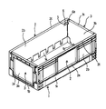
先ず最初に、図1〜図3を用いて、本発明の折り畳みコンテナーの全体構成について説明する。 First, the overall configuration of the folding container of the present invention will be described with reference to FIGS.

1は、平面形状が略長方形の底部で有り、底部1は、相対する長辺側に形成された土手部(以下、長辺側土手部という。)1aと、相対する短辺側に形成された土手部(以下、短辺側土手部という。)1bとを有しており、本実施例においては、長辺側土手部1aの高さは、短辺側土手部1bの高さより、高く形成されている。また、長辺側土手部1a及び短辺側土手部1bには、後述する雌ヒンジ部材H1が、所定の間隔で適当数、配設されている。 Reference numeral 1 denotes a bottom portion having a substantially rectangular planar shape, and the bottom portion 1 is formed on a bank portion 1a formed on the opposite long side (hereinafter, referred to as a long side bank portion) 1a and on the opposite short side. In this embodiment, the height of the long side bank portion 1a is higher than the height of the short side bank portion 1b. Is formed. Further, an appropriate number of female hinge members H1 described later are arranged at predetermined intervals on the long side bank portion 1a and the short side bank portion 1b.

2は、長側壁であり、長側壁2の下部フランジ2aの裏面には、底部1の長辺側土手部1aに配設された雌ヒンジ部材H1に対応して、後述する雄ヒンジ部材H2が配設されている。3は、短側壁であり、短側壁3の下部フランジ3aの裏面にも、底部1の短側壁土手部1bに配設された雌ヒンジ部材H1に対応して、後述する雄ヒンジ部材H2が配設されている。 2 is a long side wall, and a male hinge member H2 to be described later is provided on the back surface of the lower flange 2a of the long side wall 2 in correspondence with the female hinge member H1 disposed on the long side bank portion 1a of the bottom portion 1. It is arranged. 3 is a short side wall, and a male hinge member H2 described later is arranged on the back surface of the lower flange 3a of the short side wall 3 in correspondence with the female hinge member H1 disposed on the short side wall bank portion 1b of the bottom portion 1. It is installed.

長側壁2の下部フランジ2aに配設された雄ヒンジ部材H2と底部1の長辺側土手部1aに配設された雌ヒンジ部材H1とを連結することにより、長側壁2が、底部1にヒンジ連結され、また、短側壁3の下部フランジ3aに配設された雄ヒンジ部材H2と底部1の短辺側土手部1bに配設された雌ヒンジ部材H1とを連結することにより、短側壁3が、底部1にヒンジ連結されて、折り畳みコンテナーが構成されることになる。 By connecting the male hinge member H2 disposed on the lower flange 2a of the long side wall 2 and the female hinge member H1 disposed on the long side bank portion 1a of the bottom portion 1, the long side wall 2 is connected to the bottom portion 1. By connecting the male hinge member H2 which is hinged and disposed on the lower flange 3a of the short side wall 3 and the female hinge member H1 disposed on the short side bank portion 1b of the bottom 1, the short side wall is obtained. 3 is hinged to the bottom 1 to form a folding container.

長側壁2の横長の略長方形状の板状部2bの両端部には、板状部2bに対して略直角方向に延在する縦長の係合枠4が形成されており、係合枠4には、適当数の透孔4aが穿設されている。また、係合枠4付近に位置する板状部2bに、コの字状のスリット5を形成することにより、係合枠4側が自由端に形成された弾性舌片6が形成されている。弾性舌片6の先端部には、係合枠4と対向するように、係止凸部6aが形成されている。 A vertically long engagement frame 4 extending in a direction substantially perpendicular to the plate-like part 2 b is formed at both ends of the horizontally long and substantially rectangular plate-like part 2 b of the long side wall 2. Are provided with an appropriate number of through holes 4a. Further, by forming a U-shaped slit 5 in the plate-like portion 2b located in the vicinity of the engagement frame 4, an elastic tongue piece 6 having the engagement frame 4 side formed at a free end is formed. A locking projection 6 a is formed at the tip of the elastic tongue piece 6 so as to face the engagement frame 4.

短側壁3の横長の略長方形状の板状部3bの両端部には、板状部3bを延長することにより、縦長の係合枠7が形成されており、係合枠7には、長側壁2の係合枠4に穿設されている透孔4aに嵌合する嵌合突起7aが形成されている。 A vertically long engagement frame 7 is formed by extending the plate-like portion 3 b at both ends of the horizontally long, substantially rectangular plate-like portion 3 b of the short side wall 3. A fitting protrusion 7a is formed to fit into a through hole 4a formed in the engaging frame 4 of the side wall 2.

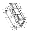
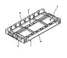
図3に示されているように、折り畳まれた状態から、図1に示されているように、箱型に組み立てるには、先ず最初に、略水平状態の長側壁2を、略垂直に立て、次いで、短側壁3を、略垂直に立てられた長側壁2方向に回動させると、短側壁3の係合枠7に形成された嵌合突起7aの長側壁2の係合枠4に穿設された透孔4aへの嵌合に前後して、短側壁3の係合枠7が、長側壁2に形成された弾性舌片6の係止凸部6aに当接し、弾性舌片6を外側に変形させる。そして、短側壁3の係合枠7が、長側壁2に形成された弾性舌片6の係止凸部6aを通過した時点で、短側壁3の係合枠7により外側に押された弾性舌片6が、その復元力により戻り、弾性舌片6の係止凸部6aが、略垂直に立てられた短側壁3の係合枠7に当接して、短側壁3の底部1方向への回動を阻止するように構成されている。 As shown in FIG. 3, in order to assemble from a folded state into a box shape as shown in FIG. 1, first, the long side wall 2 in a substantially horizontal state is first set up substantially vertically. Then, when the short side wall 3 is rotated in the direction of the long side wall 2 erected substantially vertically, the engagement frame 4 on the long side wall 2 of the fitting projection 7 a formed on the engagement frame 7 of the short side wall 3 is moved. Before and after fitting into the drilled through-hole 4a, the engagement frame 7 of the short side wall 3 comes into contact with the locking projection 6a of the elastic tongue piece 6 formed on the long side wall 2, and the elastic tongue piece 6 is deformed outward. Then, when the engagement frame 7 of the short side wall 3 passes through the locking projection 6a of the elastic tongue piece 6 formed on the long side wall 2, the elasticity pushed outward by the engagement frame 7 of the short side wall 3 The tongue piece 6 returns due to its restoring force, and the locking convex portion 6a of the elastic tongue piece 6 comes into contact with the engagement frame 7 of the short side wall 3 standing substantially vertically, toward the bottom 1 of the short side wall 3. It is comprised so that rotation of this may be blocked | prevented.

また、箱型に組み立てられた折り畳みコンテナーを、折り畳むには、先ず最初に、長側壁2の弾性舌片6を、その係止凸部6aが、短側壁3の係合枠7から外れるように、外側に押し、その後、短側壁3を底部1方向に回動させることにより、短側壁3の係合枠7に形成された嵌合突起7aを、長側壁2の係合枠4に穿設された透孔4aから排出させて、短側壁3を底部1の上に倒す。その後、略垂直な長側壁2を、底部1方向に倒すことにより、箱型に組み立てられた折り畳みコンテナーを折り畳むように構成されている。 In order to fold the folded container assembled in a box shape, first, the elastic tongue piece 6 of the long side wall 2 is first moved so that the engaging projection 6 a is disengaged from the engaging frame 7 of the short side wall 3. Then, by pushing outward, and then turning the short side wall 3 in the direction of the bottom 1, a fitting protrusion 7 a formed on the engaging frame 7 of the short side wall 3 is drilled in the engaging frame 4 of the long side wall 2. The short side wall 3 is lowered onto the bottom 1 by discharging from the through-hole 4a. Thereafter, the folding container assembled in a box shape is folded by tilting the substantially vertical long side wall 2 toward the bottom 1.

上述したように、折り畳まれた状態においては、略垂直状態から、先に倒される短側壁3は、底部1に重ねられた際には、短側壁3同士が互いに重なり合うようなことはなく、短側壁3の上部フランジ3c間には、所定の間隙が形成されるように構成されている。一方、後から倒される長側壁2は、略垂直状態から倒された際には、長側壁2同士が、互いに部分的に重なり合うように構成されている。 As described above, in the folded state, the short side walls 3 that are tilted first from the substantially vertical state do not overlap with each other when the short side walls 3 are overlapped with the bottom portion 1. A predetermined gap is formed between the upper flanges 3 c of the side walls 3. On the other hand, the long side walls 2 to be tilted later are configured such that the long side walls 2 partially overlap each other when tilted from a substantially vertical state.

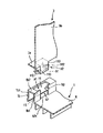
次に、図4〜図7を用いて、底部1の長辺側土手部1aに配設されている雌ヒンジ部材H1を例に、雌ヒンジ部材H1について説明するとともに、長側壁2の下部フランジ2aに配設されている雄ヒンジ部材H2を例に、雄ヒンジ部材H2について説明する。 Next, the female hinge member H1 will be described with reference to FIGS. 4 to 7 taking the female hinge member H1 disposed on the long side bank portion 1a of the bottom portion 1 as an example, and the lower flange of the long side wall 2 will be described. The male hinge member H2 will be described taking the male hinge member H2 disposed in 2a as an example.

底部1の長辺側土手部1aは、底部1の底板1cの縁部から上方に略垂直に延在する内側垂直部1a1と、内側垂直部1a1の上端から外側に略水平に延在する水平部1a2と、水平部1a2の縁部から内側垂直部1a1と略平行に下方に延在する外側垂直部1a3とから構成されており、長手方向に対して垂直な断面形状が、略逆U字状に形成されている。 The long side bank portion 1a of the bottom portion 1 includes an inner vertical portion 1a1 extending substantially vertically upward from an edge portion of the bottom plate 1c of the bottom portion 1, and a horizontal portion extending substantially horizontally outward from the upper end of the inner vertical portion 1a1. The portion 1a2 and the outer vertical portion 1a3 extending downward from the edge of the horizontal portion 1a2 substantially in parallel with the inner vertical portion 1a1, and the cross-sectional shape perpendicular to the longitudinal direction has a substantially inverted U shape. It is formed in a shape.

長辺側土手部1aの水平部1a2には、平面形状が長方形の縦孔h1が穿設されている。また、長辺側土手部1aの内側垂直部1a1には、上方が開放されているとともに、底板1c方向に延在する方形状の切欠き凹部h2が形成されている。切欠き凹部h2の横幅(長辺側土手部1aの長手方向に沿った長さ)W1は、縦孔h1の長辺長さ(長辺側土手部1aの長手方向に沿った長さ)W2aより短く、且つ、切欠き凹部h2は、縦孔h1の長辺の略中央部に位置している。 A vertical hole h1 having a rectangular planar shape is formed in the horizontal portion 1a2 of the long side bank portion 1a. In addition, the inner vertical portion 1a1 of the long side bank portion 1a is formed with a rectangular cutout recess h2 that is open at the top and extends in the direction of the bottom plate 1c. The width (length along the longitudinal direction of the long side bank portion 1a) W1 of the notch recess h2 is the long side length (length along the longitudinal direction of the long side bank portion 1a) W2a of the vertical hole h1. The shorter and cut-out recess h2 is located at a substantially central portion of the long side of the vertical hole h1.

切欠き凹部h2の両側に位置する内側垂直部1a1の内面(外側垂直部1a3側に位置する面)の上端部には、フックh3が突設されており、フックh3は、長辺側土手部1aの水平部1a2から外側垂直部1a3に向かって、外側垂直部1a3に徐々に接近するように傾斜した上部傾斜面h3aと略水平な庇部h3bとにより構成されている。 A hook h3 protrudes from the upper end portion of the inner surface of the inner vertical portion 1a1 (surface located on the outer vertical portion 1a3 side) located on both sides of the notch recess h2, and the hook h3 is a long side bank portion. An upper inclined surface h3a that is inclined so as to gradually approach the outer vertical portion 1a3 from the horizontal portion 1a2 toward the outer vertical portion 1a3 and a substantially horizontal flange portion h3b.

上述した長辺側土手部1aに形成された縦孔h1と切欠き凹部h2とフックh3とにより、雌ヒンジ部材H1が構成されている。 The female hinge member H1 is comprised by the vertical hole h1, the notch recessed part h2, and the hook h3 which were formed in the long side bank part 1a mentioned above.

一方、長側壁2の板状部2bに垂直な下部フランジ2aの裏面には、雄ヒンジ部材H2が形成されている。雄ヒンジブ部材H2は、所定の間隔をおいて、且つ、下部フランジ2aの長手方向に対して垂直に、下部フランジ2aの裏面に垂設されている板状の支持片h10を有しており、一対の支持片h10は、連結片h11により連結されている。一対の支持片h10の外側面(一対の支持片h10の相対する面とは反対側の面)間の幅W3は、切欠き凹部h2の横幅W1より、若干、狭く形成されており、一対の支持片h10が、切欠き凹部h2に挿入可能なように構成されている。また、一対の支持片h10の外側面の下端部には、ヒンジブロックh12が取着されており、ヒンジブロックh12の下部フランジ2aとの対向面(以下、上面という。)h12aは、下部フランジ2aと略平行な平坦面として形成されており、更に、上記の上面h12aの板状部2b側に位置する端部には、略直方体状の当接ブロック部h12bが突設されている。 On the other hand, a male hinge member H2 is formed on the back surface of the lower flange 2a perpendicular to the plate-like portion 2b of the long side wall 2. The male hinge member H2 has a plate-like support piece h10 that is suspended from the back surface of the lower flange 2a at a predetermined interval and perpendicular to the longitudinal direction of the lower flange 2a. The pair of support pieces h10 are connected by a connecting piece h11. The width W3 between the outer surfaces of the pair of support pieces h10 (the surface opposite to the surface opposite to the pair of support pieces h10) is formed slightly narrower than the lateral width W1 of the notch recess h2. The support piece h10 is configured to be insertable into the notch recess h2. Further, a hinge block h12 is attached to the lower end portion of the outer side surface of the pair of support pieces h10, and a surface facing the lower flange 2a of the hinge block h12 (hereinafter referred to as the upper surface) h12a is the lower flange 2a. Further, a substantially rectangular parallelepiped contact block h12b projects from an end portion of the upper surface h12a located on the plate-like portion 2b side.

ヒンジブロックh12の下部フランジ2aに対して垂直方向の幅(ヒンジブロックh12の底面h12cから当接ブロック部h12bの上面までの高さ)W4は、底部1の長辺側土手部1aの外側垂直部1a3と内側垂直部1a1の内面に突設されたフックh3の先端との間の間隙W5より、若干、広く形成されている。 The width W4 in the direction perpendicular to the lower flange 2a of the hinge block h12 (the height from the bottom surface h12c of the hinge block h12 to the top surface of the contact block portion h12b) W4 is the outer vertical portion of the long side bank portion 1a of the bottom portion 1 It is formed slightly wider than the gap W5 between 1a3 and the tip of the hook h3 projecting from the inner surface of the inner vertical portion 1a1.

上述した一対の支持片h10と連結片h11と当接ブロック部h12bを有するヒンジブロックh12とにより、雄ヒンジ部材H2が構成されている。 The pair of supporting pieces h10, the connecting piece h11, and the hinge block h12 having the contact block portion h12b constitute a male hinge member H2.

雄ヒンジ部材H2の長側壁2の板状部2bに沿った幅(一対のヒンジブロックh12の垂直側面h12d間の間隔)W6は、雌ヒンジ部材H1を構成する縦孔h1の長辺長さW2aより、若干、短く、また、一対の支持片h10の厚さ(長側壁2の板状部2bに対して、垂直方向の長さ)W7は、雌ヒンジ部材H1を構成する縦孔h1の短辺長さ(長辺側土手部1aの長手方向に対して垂直方向の長さ)W2bより、若干、短く形成されており、従って、長側壁2の下部フランジ2aの裏面に形成された雄ヒンジ部材H2は、雌ヒンジ部材H1を形成する長辺側土手部1aに形成された縦孔h1に挿入可能なように構成されている。 The width (interval between the vertical side surfaces h12d of the pair of hinge blocks h12) W6 along the plate-like portion 2b of the long side wall 2 of the male hinge member H2 is the long side length W2a of the vertical hole h1 constituting the female hinge member H1. Further, it is slightly shorter, and the thickness of the pair of support pieces h10 (the length in the direction perpendicular to the plate-like portion 2b of the long side wall 2) W7 is short of the vertical hole h1 constituting the female hinge member H1. The male hinge formed on the back surface of the lower flange 2a of the long side wall 2 is slightly shorter than the side length (the length in the direction perpendicular to the longitudinal direction of the long side bank portion 1a) W2b. The member H2 is configured to be insertable into a vertical hole h1 formed in the long side bank portion 1a that forms the female hinge member H1.

底部1と長側壁2とをヒンジ連結するには、図5に示されているように、長側壁2を、底部1と略平行になるように、略水平状態に配置し、その後、その状態を維持したまま、長側壁2を、底部1に向かって下降させ、長側壁2に形成されたヒンジブロックh12が突設されている支持片h10を、長辺側土手部1aに形成された切欠き凹部h2に挿入するとともに、ヒンジブロックh12を、長辺側土手部1aに形成された縦孔h1に挿入すると、ヒンジブロックh12の下部フランジ2aに対して垂直方向の幅W4は、底部1の長辺側土手部1aの外側垂直部1a3と内側垂直部1a1の内面に突設されたフックh3の先端との間の間隙W5より、若干、広く形成されているので、ヒンジブロックh12は、図5に示されているように、底部1の長辺側土手部1aの内側垂直部1a1に形成された切欠き凹部h2の両側に位置する内側垂直部1a1の内面に突設されたフックh3の上部傾斜面h3aに載置されることになる。その後、長側壁2と底部1とが略水平状態を維持したまま、長側壁2を、更に、底部1に向かって、強制的に下降させると、ヒンジブロックh12は、長辺側土手部1aの内側垂直部1a1或いは/及び外側垂直部1a3を湾曲変形させて、底部1に形成された長辺側土手部1aの外側垂直部1a3と内側垂直部1a1の内面に突設されたフックh3との間の間隙W5を拡げることにより、長辺側土手部1aの外側垂直部1a3と内側垂直部1a1の内面に突設されたフックh3との間を通過し、図6に示されているように、底部1に形成された長辺側土手部1aの外側垂直部1a3と内側垂直部1a1との間に配置されることになる。このようにして、底部1の長辺側土手部1aに配設された雌ヒンジ部材H1と長側壁2に配設された雄ヒンジ部材H2とがヒンジ連結されることになる。 In order to hinge-connect the bottom 1 and the long side wall 2, as shown in FIG. 5, the long side wall 2 is arranged in a substantially horizontal state so as to be substantially parallel to the bottom 1, and then the state is maintained. The long side wall 2 is moved downward toward the bottom 1 while maintaining the above-mentioned, and the support piece h10 on which the hinge block h12 formed on the long side wall 2 is projected is cut off on the long side bank portion 1a. When the hinge block h12 is inserted into the notched recess h2 and the hinge block h12 is inserted into the vertical hole h1 formed in the long side bank portion 1a, the width W4 perpendicular to the lower flange 2a of the hinge block h12 is The hinge block h12 is slightly wider than the gap W5 between the outer vertical portion 1a3 of the long side bank portion 1a and the tip of the hook h3 projecting from the inner surface of the inner vertical portion 1a1. As shown in Figure 5, The long side bank portion 1a of the portion 1 is placed on the upper inclined surface h3a of the hook h3 projecting from the inner surface of the inner vertical portion 1a1 located on both sides of the notch concave portion h2 formed in the inner vertical portion 1a1. It will be. Thereafter, when the long side wall 2 and the bottom portion 1 are maintained in a substantially horizontal state and the long side wall 2 is further forcibly lowered toward the bottom portion 1, the hinge block h12 is moved to the long side bank portion 1a. The inner vertical portion 1a1 and / or the outer vertical portion 1a3 are curved and deformed, and the outer vertical portion 1a3 of the long side bank portion 1a formed on the bottom portion 1 and the hook h3 protruding from the inner surface of the inner vertical portion 1a1 By widening the gap W5 between them, it passes between the outer vertical portion 1a3 of the long side bank portion 1a and the hook h3 protruding from the inner surface of the inner vertical portion 1a1, and as shown in FIG. The long side bank portion 1a formed on the bottom portion 1 is disposed between the outer vertical portion 1a3 and the inner vertical portion 1a1. In this way, the female hinge member H1 disposed on the long side bank portion 1a of the bottom portion 1 and the male hinge member H2 disposed on the long side wall 2 are hinge-connected.

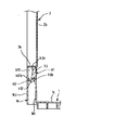
折り畳みコンテナーが折り畳まれた状態から、略水平状態の長側壁2を、略垂直に立てると、図7に示されているように、ヒンジブロックh12の当接ブロック部h12bが、底部1に形成された長辺側土手部1aの内側垂直部1a1に突設されたフックh3の庇部h3bの下に入り込むとともに、長側壁2の下部フランジ2aが、底部1の長辺側土手部1aの水平部1a2に載置されることになる。そして、フックh3の庇部h3bの下に入り込んだヒンジブロックh12の当接ブロック部h12bは、フックh3の庇部h3bと当接するように、或いは、庇部h3bに接近した位置をとるように構成されており、従って、折り畳みコンテナーが、箱型に組み立てられた状態においては、長側壁2が、上下方向にがたつくようなことがない。 When the substantially horizontal long side wall 2 is stood substantially vertically from the folded state of the folding container, a contact block portion h12b of the hinge block h12 is formed on the bottom portion 1 as shown in FIG. In addition, the lower flange 2a of the long side wall 2 enters the horizontal portion of the long side bank portion 1a of the bottom portion 1 while entering under the hook portion h3b of the hook h3 protruding from the inner vertical portion 1a1 of the long side bank portion 1a. It will be placed on 1a2. The contact block portion h12b of the hinge block h12 that has entered under the hook portion h3b of the hook h3 is configured to contact the hook portion h3b of the hook h3 or take a position close to the hook portion h3b. Therefore, in a state where the folding container is assembled in a box shape, the long side wall 2 does not rattle in the vertical direction.

図8に示されているように、底部1の短辺側土手部1bは、長辺側土手部1aに比べて、高さが低いだけで、その構成は実質的に同じであり、底部1の底板1cの縁部から上方に略垂直に延在する内側垂直部1b1と、内側垂直部1b1の上端から外側に略水平に延在する水平部1b2と、水平部1b2の縁部から内側垂直部1b1と略平行に下方に延在する外側垂直部1b3とから構成されており、短辺側土手部1bにも、上述した雌ヒンジ部材H1が形成されている。また、短側壁3の下部フランジ短側壁3の下部フランジ3aの裏面にも、底部1の短側壁土手部1bに配設された雌ヒンジ部材H1に対応して、上述した雄ヒンジ部材H2が形成されている。そして、底部1の短辺側土手部1bに配設された雌ヒンジ部材H1と短側壁3に配設された雄ヒンジ部材H2とがヒンジ連結されることになる。 As shown in FIG. 8, the short side bank portion 1 b of the bottom portion 1 is substantially the same in configuration as the bottom side portion 1 b only having a lower height than the long side side bank portion 1 a. An inner vertical portion 1b1 extending substantially vertically upward from the edge of the bottom plate 1c, a horizontal portion 1b2 extending substantially horizontally outward from the upper end of the inner vertical portion 1b1, and an inner vertical from the edge of the horizontal portion 1b2. The above-described female hinge member H1 is also formed on the short side bank portion 1b. The outer vertical portion 1b3 extends downward substantially parallel to the portion 1b1. Also, the above-described male hinge member H2 is formed on the back surface of the lower flange 3a of the short side wall 3 corresponding to the female hinge member H1 disposed on the short side wall bank portion 1b of the bottom 1 on the back surface of the lower flange 3a. Has been. And the female hinge member H1 arrange | positioned by the short side bank part 1b of the bottom part 1 and the male hinge member H2 arrange | positioned by the short side wall 3 are hinge-connected.

底部1の短辺側土手部1bに形成されている雌ヒンジ部材H1を構成する切欠き凹部h2は、底部1の底板1cまで、或いは、底板1c付近まで延在している。換言すれば、切欠き凹部h2の下端h2aは、底部1の底板1cと面一か、或いは、底板1c付近に位置している。このように構成することにより、短側壁3を、図2に示されているように、底部1方向に倒した際に、短側壁3に配設された雄ヒンジ部材H2の支持片h10が、短辺側土手部1bに形成されている雌ヒンジ部材H1を構成する切欠き凹部h2の下端h2aに当接するようなことがなく、図9に示されているように、短側壁3の板状部3bの略全面が、底部1の底板1cに実質的に接触するように、短側壁3を、底部1の底板1cに重ねることができる。なお、図8に示されているように、本実施例には、切欠き凹部h2の下端h2aが、底部1の底板1cと面一の場合が示されている。 A notch recess h2 constituting the female hinge member H1 formed in the short side bank portion 1b of the bottom portion 1 extends to the bottom plate 1c of the bottom portion 1 or to the vicinity of the bottom plate 1c. In other words, the lower end h2a of the notch recess h2 is positioned flush with the bottom plate 1c of the bottom 1 or in the vicinity of the bottom plate 1c. With this configuration, when the short side wall 3 is tilted toward the bottom 1 as shown in FIG. 2, the support piece h10 of the male hinge member H2 disposed on the short side wall 3 is As shown in FIG. 9, the plate-like shape of the short side wall 3 does not come into contact with the lower end h2a of the notch recess h2 constituting the female hinge member H1 formed on the short side bank portion 1b. The short side wall 3 can be overlapped with the bottom plate 1 c of the bottom portion 1 so that the substantially entire surface of the portion 3 b substantially contacts the bottom plate 1 c of the bottom portion 1. As shown in FIG. 8, the present embodiment shows a case where the lower end h <b> 2 a of the notch recess h <b> 2 is flush with the bottom plate 1 c of the bottom portion 1.

長辺側土手部1aの内側垂直部1a1に形成されている切欠き凹部h2の両側に位置する内側垂直部1a1の内面の上端部に突設されたフックh3の庇部h3bの下に位置している切欠き凹部h2の高さ、換言すれば、フックh3の庇部h3bから切欠き凹部h2の下端h2aまでの高さW8は、雄ヒンジ部材H2を構成する支持片h10の厚さW7の2倍以上の高さを有している。また、長辺側土手部1aの内側垂直部1a1に形成されている切欠き凹部h2の下端h2aは、底部1の底板1cの略全面に接触するように、底部1の底板1cに重ねられた状態の短側壁3の上面と略同じ位置、或いは、それ以下に位置するように構成されている。 Located below the flange h3b of the hook h3 projecting from the upper end of the inner surface of the inner vertical portion 1a1 located on both sides of the notch recess h2 formed on the inner vertical portion 1a1 of the long side bank portion 1a. The height W8 of the cut-out recess h2, in other words, the height W8 from the flange h3b of the hook h3 to the lower end h2a of the cut-out recess h2 is equal to the thickness W7 of the support piece h10 constituting the male hinge member H2. The height is twice or more. Further, the lower end h2a of the notch concave portion h2 formed in the inner vertical portion 1a1 of the long side bank portion 1a is overlapped with the bottom plate 1c of the bottom portion 1 so as to contact substantially the entire surface of the bottom plate 1c of the bottom portion 1. It is comprised so that it may be located in the substantially the same position as the upper surface of the short side wall 3 of a state, or it below.

箱型に組み立てられた折り畳みコンテナーを折り畳むには、上述したように、先ず最初に、略垂直な相対する短側壁3を、底部1方向に倒して、底部1に重ねる。このようにして、略水平状態に、底部1に重ねられた相対する短側壁3は、短側壁3同士が、部分的にせよ、互いに重なり合うようなことはない。次いで、略垂直な相対する長側壁2のうちの一方の長側壁2を、底部1方向に倒して、底部1に重ねられた短側壁3の上に重ねることになるが、略垂直状態の一方の長側壁2の底部1方向への回動途中において、長辺側土手部1aの水平部1a2に載置されていた、一方の長側壁2の下部フランジ2aが、水平部1a2から外れることになる。その後、一方の長側壁2を略水平状態に維持したまま、一方の長側壁2に配設された雄ヒンジ部材H2の支持片h10を、長辺側土手部1aに形成されている雌ヒンジ部材H1を構成する切欠き凹部h2に沿って下方に移動させて、一方の長側壁2の板状部2bの略全面が、底部1に重ねられている短側壁3に接触するように、一方の長側壁2を、底部1に重なるように先に倒されている短側壁3の上に略水平状態に重ねる。 In order to fold a folding container assembled in a box shape, first, as described above, first, the nearly vertical opposing short side walls 3 are tilted toward the bottom 1 and overlapped with the bottom 1. In this way, the opposing short side walls 3 that are superimposed on the bottom 1 in a substantially horizontal state do not overlap each other, even if the short side walls 3 are partially. Next, one long side wall 2 of the substantially vertical opposing long side walls 2 is tilted in the direction of the bottom portion 1 and is superimposed on the short side wall 3 superimposed on the bottom portion 1. During the rotation of the long side wall 2 toward the bottom 1, the lower flange 2 a of one long side wall 2 placed on the horizontal portion 1 a 2 of the long side bank portion 1 a is detached from the horizontal portion 1 a 2. Become. Thereafter, the supporting piece h10 of the male hinge member H2 disposed on one long side wall 2 is formed on the long side bank portion 1a while the one long side wall 2 is maintained in a substantially horizontal state. One of the long side walls 2 of the plate-like portion 2b is moved downward along the notch recess h2 constituting the H1 so that the substantially entire surface of the plate-like portion 2b of the long side wall 2 is in contact with the short side wall 3 superimposed on the bottom portion 1. The long side wall 2 is overlapped in a substantially horizontal state on the short side wall 3 that has been tilted first so as to overlap the bottom portion 1.

次いで、相対する略垂直な長側壁2のうちのもう一方の長側壁2を、底部1方向に倒して、先に略水平状態に、短側壁3の上に重ねられた一方の長側壁2の上に重ねることになるが、相対する略垂直な長側壁2のうちの先に倒された長側壁2は、上述したように、底部1に重なるように先に倒されている短側壁3の上に略水平状態に重ねられているので、後から倒される長側壁2が、先に倒された略水平状態の長側壁2に、部分的に面接触するように、先に倒された略水平状態の長側壁2の上に、略水平状態に重ねられることになる。 Next, the other long side wall 2 of the opposed substantially vertical long side walls 2 is tilted in the direction of the bottom portion 1 so that the first long side wall 2 overlaid on the short side wall 3 is placed in a substantially horizontal state first. As described above, the long side wall 2 that has been tilted forward of the opposing substantially vertical long side walls 2 is superimposed on the short side wall 3 that has been tilted first so as to overlap the bottom 1 as described above. Since the long side wall 2 to be tilted later is partly brought into surface contact with the long side wall 2 that has been tilted first, it has been tilted first. On the long side wall 2 in the horizontal state, it is superimposed in a substantially horizontal state.

上述したようにして、図3や図6に示されているように、部分的に互いに重なり合うように倒される一対の長側壁2を、略水平状態に、先に底部1に重なるように倒された略水平状態の短側壁3の重ねることができるので、折り畳まれた状態の折り畳みコンテナーの高さを、一対の長側壁2が傾斜状態で重ねられる従来の折り畳みコンテナーに比べて、低くすることができ、従って、折り畳まれた状態の折り畳みコンテナーを段積みして収容する際の収容効率を向上することができる。 As described above, as shown in FIG. 3 and FIG. 6, the pair of long side walls 2 that are partially collapsed so as to overlap each other are tilted so as to overlap the bottom 1 in a substantially horizontal state. Since the short side walls 3 in a substantially horizontal state can be stacked, the height of the folded container in the folded state can be made lower than that in a conventional folding container in which the pair of long side walls 2 are stacked in an inclined state. Therefore, it is possible to improve the storage efficiency when stacking and storing the folded containers in the folded state.

上述した実施例には、高さの高い長辺側土手部1aに、長側壁2をヒンジ連結し、高さの低い短辺側土手部1bに、短側壁3をヒンジ連結し、箱型に組み立てられた折り畳みコンテナーを折り畳むには、最初に、相対する短側壁3を、底部1に重なるように対し、次いで、相対する長側壁2のうちの一方の長側壁2を、短側壁3に重なるように略水平状態に倒し、その後、相対する長側壁2のうちのもう一方の長側壁2を、一方の長側壁2に重なるように略水平状態に倒すようにした例が示されているが、短辺側土手部1bの高さを、長辺側土手部1aの高さより高くすることにより、最初に、相対する長側壁2の一方の長側壁2を、底部1に重なるように略水平状態に倒し、次いで、もう一方の長側壁2を、一方の長側壁2に重なるように略水平状態に倒し、その後、相対する短側壁3を、もう一方の長側壁2に重なるように倒すように構成することもできる。 In the embodiment described above, the long side wall portion 1a having a high height is hinged to the long side wall 2, the short side wall portion 1b having a low height is hinged to the short side wall 3, and the box shape is obtained. To fold the assembled folding container, first, the opposing short side wall 3 overlaps the bottom 1, then one of the opposing long side walls 2 overlaps the short side wall 3. In the example shown in FIG. 2, the other long side wall 2 of the opposing long side walls 2 is tilted in a substantially horizontal state so as to overlap the one long side wall 2. By making the height of the short side bank portion 1b higher than the height of the long side side bank portion 1a, first, one long side wall 2 of the opposing long side walls 2 is substantially horizontal so as to overlap the bottom portion 1. Then, the other long side wall 2 is overlapped with one long side wall 2 Fold horizontal state, then, opposing the short side wall 3, it can also be configured to defeat so as to overlap the other to one of the long side wall 2.

図1は、箱型に組み立てられた状態の本発明の折り畳みコンテナーの斜視図である。FIG. 1 is a perspective view of the folding container of the present invention in a state of being assembled into a box shape. 図2は、組み立て途中或いは折り畳み途中の本発明の折り畳みコンテナーの斜視図である。FIG. 2 is a perspective view of the folding container of the present invention during assembly or folding. 図3は、折り畳まれた状態の本発明の折り畳みコンテナーの斜視図である。FIG. 3 is a perspective view of the folding container of the present invention in a folded state. 図4は、本発明の折り畳みコンテナーの長側壁と底部とのヒンジ連結を説明するための部分分解斜視図である。FIG. 4 is a partially exploded perspective view for explaining the hinge connection between the long side wall and the bottom of the folding container according to the present invention. 図5は、本発明の折り畳みコンテナーの長側壁と底部とのヒンジ連結を説明するためのヒンジ連結部分の垂直断面図である。FIG. 5 is a vertical cross-sectional view of the hinge connection portion for explaining the hinge connection between the long side wall and the bottom of the folding container of the present invention. 図6は、同じく、本発明の折り畳みコンテナーの長側壁と底部とのヒンジ連結を説明するためのヒンジ連結部分の垂直断面図である。FIG. 6 is also a vertical sectional view of a hinge connection portion for explaining the hinge connection between the long side wall and the bottom of the folding container of the present invention. 図7は、同じく、本発明の折り畳みコンテナーの長側壁と底部とのヒンジ連結を説明するためのヒンジ連結部分の垂直断面図である。FIG. 7 is also a vertical sectional view of a hinge connection portion for explaining the hinge connection between the long side wall and the bottom of the folding container of the present invention. 図8は、本発明の折り畳みコンテナーの短側壁と底部とのヒンジ連結を説明するための部分分解斜視図である。FIG. 8 is a partially exploded perspective view for explaining the hinge connection between the short side wall and the bottom of the folding container according to the present invention. 図9は、本発明の折り畳みコンテナーの短側壁が底部に重ねられた状態のヒンジ連結部分の垂直断面図である。FIG. 9 is a vertical cross-sectional view of the hinge connecting portion in a state where the short side wall of the folding container of the present invention is overlapped with the bottom.

符号の説明Explanation of symbols

H1・・・・・・・・・・・・・雌ヒンジ部材
h1・・・・・・・・・・・・・縦孔
h2・・・・・・・・・・・・・切欠き凹部
h3・・・・・・・・・・・・・フック
H2・・・・・・・・・・・・・雄ヒンジ部材
h10・・・・・・・・・・・・支持片
h12・・・・・・・・・・・・ヒンジブロック
1・・・・・・・・・・・・・・底部
1a・・・・・・・・・・・・・長辺側土手部
1a1・・・・・・・・・・・・内側垂直部
1a2・・・・・・・・・・・・水平部
1a3・・・・・・・・・・・・外側垂直部
1c・・・・・・・・・・・・・底板
1b・・・・・・・・・・・・・短辺側土手部
2・・・・・・・・・・・・・・長側壁
3・・・・・・・・・・・・・・短側壁
H1 ····························································································· ...... h3 ... hook H2 ... male hinge member h10 ... support piece h12 ............ Hinge block 1 ......... Bottom 1a ......... Long-side bank 1a1 ...・ ・ ・ ・ ・ ・ ・ ・ ・ ・ Inner vertical part 1a2 ・ ・ ・ ・ ・ ・ ・ ・ ・ ・ ・ Horizontal part 1a3 ・ ・ ・ ・ ・ ・ ・ ・ ・ ・ ・ Outer vertical part 1c ・ ・ ・ ・ ・・ ・ ・ ・ ・ ・ ・ ・ Bottom plate 1b ・ ・ ・ ・ ・ ・ ・ ・ Short side bank 2 ・ ・ ・ ・ ・ ・ ・ ・ ・ ・ ・ ・ ・ Long side wall 3 ・ ・ ・・ ・ ・ ・ ・ ・ ・ ・ ・ ・ Short side wall

Claims (1)

底部の一方の相対する辺部に形成された土手部に、一方の相対する側壁がヒンジ連結され、底部のもう一方の相対する辺部に形成された土手部に、もう一方の相対する側壁がヒンジ連結されているとともに、箱型に組み立てられた状態から、前記側部を底部方向に倒すことにより折り畳むように構成された折り畳みコンテナーにおいて、互いに部分的に重なり合う側壁が底部方向に倒された際に、前記互いに部分的に重なり合う側壁に形成された雄ヒンジ部材が、該雄ヒンジ部材に対応して、前記底部の土手部に形成された雌ヒンジ部材の切欠き凹部内を移動可能としたことを特徴とする折り畳みコンテナー。 One opposite side wall is hinged to the bank formed on one opposite side of the bottom, and the other opposite side wall is connected to the bank formed on the other opposite side of the bottom. In a folding container that is hinged and configured to be folded from the state assembled in a box shape by tilting the side portion toward the bottom, when the side walls that partially overlap each other are tilted toward the bottom In addition, the male hinge member formed on the side wall partially overlapping each other can move within the notch recess of the female hinge member formed on the bank portion corresponding to the male hinge member. Folding container characterized by.
JP2004120357A 2004-04-15 2004-04-15 Folding container Expired - Lifetime JP4328258B2 (en)

Priority Applications (1)

Application Number Priority Date Filing Date Title
JP2004120357A JP4328258B2 (en) 2004-04-15 2004-04-15 Folding container

Applications Claiming Priority (1)

Application Number Priority Date Filing Date Title
JP2004120357A JP4328258B2 (en) 2004-04-15 2004-04-15 Folding container

Publications (2)

Publication Number Publication Date
JP2005298043A true JP2005298043A (en) 2005-10-27
JP4328258B2 JP4328258B2 (en) 2009-09-09

Family

ID=35330067

Family Applications (1)

Application Number Title Priority Date Filing Date
JP2004120357A Expired - Lifetime JP4328258B2 (en) 2004-04-15 2004-04-15 Folding container

Country Status (1)

Country Link
JP (1) JP4328258B2 (en)

Cited By (1)

* Cited by examiner, † Cited by third party
Publication number Priority date Publication date Assignee Title
JP2009126574A (en) * 2007-11-28 2009-06-11 Sanko Co Ltd Folding container

Cited By (1)

* Cited by examiner, † Cited by third party
Publication number Priority date Publication date Assignee Title
JP2009126574A (en) * 2007-11-28 2009-06-11 Sanko Co Ltd Folding container

Also Published As

Publication number Publication date
JP4328258B2 (en) 2009-09-09

Similar Documents

Publication Publication Date Title
JP4502823B2 (en) Folding container
JP4684880B2 (en) Folding container
JP4328258B2 (en) Folding container
JP4502623B2 (en) Folding container
JP4279762B2 (en) Folding container
JP4939356B2 (en) Folding container
JP4319941B2 (en) Folding container
JP4167962B2 (en) Folding container
JP4530643B2 (en) Assembling the folding container
JP2006160315A (en) Folding container with lid
JP4263983B2 (en) Folding container
JP4250567B2 (en) Folding container
JP4652037B2 (en) Folding container with lid
JP2003020036A (en) Folding container
JP2006051966A (en) Folding container
JP4263981B2 (en) Folding container
JP4601443B2 (en) Folding container
JP4602781B2 (en) Folding container
JP4125207B2 (en) Folding container
JP3939181B2 (en) Folding container
JP3902496B2 (en) Folding container
JP2004131092A (en) Foldable container
JP4436168B2 (en) Folding container
JP4684768B2 (en) Folding container
JP2006160318A (en) Folding container with lid

Legal Events

Date Code Title Description
A621 Written request for application examination

Free format text: JAPANESE INTERMEDIATE CODE: A621

Effective date: 20060331

A977 Report on retrieval

Free format text: JAPANESE INTERMEDIATE CODE: A971007

Effective date: 20080514

A131 Notification of reasons for refusal

Free format text: JAPANESE INTERMEDIATE CODE: A131

Effective date: 20080708

A521 Written amendment

Free format text: JAPANESE INTERMEDIATE CODE: A523

Effective date: 20080718

A131 Notification of reasons for refusal

Free format text: JAPANESE INTERMEDIATE CODE: A131

Effective date: 20090203

A521 Written amendment

Free format text: JAPANESE INTERMEDIATE CODE: A523

Effective date: 20090223

TRDD Decision of grant or rejection written
A01 Written decision to grant a patent or to grant a registration (utility model)

Free format text: JAPANESE INTERMEDIATE CODE: A01

Effective date: 20090526

A01 Written decision to grant a patent or to grant a registration (utility model)

Free format text: JAPANESE INTERMEDIATE CODE: A01

A61 First payment of annual fees (during grant procedure)

Free format text: JAPANESE INTERMEDIATE CODE: A61

Effective date: 20090612

FPAY Renewal fee payment (event date is renewal date of database)

Free format text: PAYMENT UNTIL: 20120619

Year of fee payment: 3

R150 Certificate of patent or registration of utility model

Ref document number: 4328258

Country of ref document: JP

Free format text: JAPANESE INTERMEDIATE CODE: R150

Free format text: JAPANESE INTERMEDIATE CODE: R150

FPAY Renewal fee payment (event date is renewal date of database)

Free format text: PAYMENT UNTIL: 20120619

Year of fee payment: 3

FPAY Renewal fee payment (event date is renewal date of database)

Free format text: PAYMENT UNTIL: 20150619

Year of fee payment: 6

R250 Receipt of annual fees

Free format text: JAPANESE INTERMEDIATE CODE: R250

R250 Receipt of annual fees

Free format text: JAPANESE INTERMEDIATE CODE: R250

R250 Receipt of annual fees

Free format text: JAPANESE INTERMEDIATE CODE: R250

R250 Receipt of annual fees

Free format text: JAPANESE INTERMEDIATE CODE: R250