JP2005298041A - Gas replacement method for granular materials - Google Patents
Gas replacement method for granular materials Download PDFInfo
- Publication number
- JP2005298041A JP2005298041A JP2004120202A JP2004120202A JP2005298041A JP 2005298041 A JP2005298041 A JP 2005298041A JP 2004120202 A JP2004120202 A JP 2004120202A JP 2004120202 A JP2004120202 A JP 2004120202A JP 2005298041 A JP2005298041 A JP 2005298041A
- Authority
- JP
- Japan
- Prior art keywords
- gas
- replacement
- sealed container
- pressure
- granular material
- Prior art date
- Legal status (The legal status is an assumption and is not a legal conclusion. Google has not performed a legal analysis and makes no representation as to the accuracy of the status listed.)
- Granted
Links
Images


Landscapes
- Vacuum Packaging (AREA)
Abstract
【課題】簡単な置換ガスの圧力制御により短時間で効率的に粉粒状物に対するガス置換を行うことができ、また、自動ラインに組み入れやすい粉粒状物に対するガス置換方法を提供する。
【解決手段】粉粒状物1を収容した密閉容器2内に置換ガスを供給して上記密閉容器2内を昇圧し、この昇圧後に上記置換ガスを密閉容器2外へ放出して脱圧する。したがって、密閉容器2内が昇圧される際に、粉粒状物1全域に置換ガスが侵入し、その後、密閉容器2内が脱圧されることにより、粉粒状物1内に残留している空気が放出されて、ガス置換が効果的になされる。上記昇圧と脱圧によって、粉粒状物1が移動するようなガス流が発生しないので、粉粒状物1に異常な挙動が発生しない。
【選択図】図1Provided is a gas replacement method for a granular material which can be efficiently replaced in a short time by simple pressure control of the replacement gas and which can be easily incorporated into an automatic line.
A replacement gas is supplied into a hermetic container 2 containing a powdered granular material 1 to increase the pressure in the hermetic container 2, and after this pressure increase, the replacement gas is discharged out of the hermetic container 2 and depressurized. Therefore, when the inside of the sealed container 2 is pressurized, the replacement gas enters the entire area of the powdered granular material 1, and then the air remaining in the powdered granular material 1 is depressurized in the sealed container 2. Is released, and gas replacement is effectively performed. Since the gas flow in which the granular material 1 moves is not generated by the pressure increase and depressurization, abnormal behavior does not occur in the granular material 1.
[Selection] Figure 1
Description
本発明は、食料や薬剤等の粉粒状物を袋等の容器に充填するのに際して、上記粉粒状物内に残留している空気を不活性ガス等の特定のガスに効率的に置換する粉粒状物に対するガス置換方法に関するものである。 The present invention is a powder that efficiently replaces the air remaining in the granular material with a specific gas such as an inert gas when filling the granular material such as food or medicine into a container such as a bag. The present invention relates to a gas replacement method for particulate matter.
従来から、各種の物質を特定のガス雰囲気内に封入することが行われている。例えば、食料品や薬剤などの酸化劣化を防止して保存するため、これらの物質を袋詰する際に、袋内を窒素ガス等の不活性ガス雰囲気として封入することが行われている。ここで、封入する対象物質が粉体等の粉粒状物である場合、粉体にもともと含まれているガスを置換ガスに置換するのが非常に難しいという問題点があった。すなわち、粉体の場合は、粒子が微細であるため、粉体粒子の周囲に存在するガスが細かな粒子の集合体の内部に封入された状態となっており、これを置換するのが非常に困難であった。 Conventionally, various substances are sealed in a specific gas atmosphere. For example, in order to prevent and store oxidative deterioration of food products and drugs, the inside of the bag is sealed as an inert gas atmosphere such as nitrogen gas when packing these substances. Here, when the target substance to be encapsulated is a granular material such as a powder, there is a problem that it is very difficult to replace the gas originally contained in the powder with a replacement gas. That is, in the case of powder, since the particles are fine, the gas present around the powder particles is sealed inside the aggregate of fine particles, and it is extremely difficult to replace this. It was difficult.
すなわち、粉体が充填された袋の上部開口付近の空気層は比較的簡単にガス置換されるものの、袋の内部や底部近傍の空気はほとんど置換されず、上部層の残留酸素濃度を0.5%以下までガス置換を行って封止したとしても、時間が経過すると内部や底部に残留した酸素が拡散して袋内の酸素濃度は5〜10%程度となってしまい、酸化劣化を防止するという目的からは不十分なものであった。また、粉体中の酸素を十分に不活性ガス等に置換するためには、不活性ガスを大流量で供給する必要があり、粉体が舞い上がって袋詰に支障をきたしていた。 That is, the air layer in the vicinity of the top opening of the bag filled with powder is relatively easily replaced with gas, but the air in the bag and in the vicinity of the bottom is hardly replaced, and the residual layer has a residual oxygen concentration of 0. Even if gas replacement is performed up to 5% or less and sealing is performed, oxygen remaining in the interior and bottom portion diffuses over time, and the oxygen concentration in the bag becomes about 5 to 10%, preventing oxidation deterioration. It was insufficient for the purpose of doing. In addition, in order to sufficiently replace oxygen in the powder with an inert gas or the like, it is necessary to supply the inert gas at a large flow rate, and the powder has risen and hinders bagging.
そこで、粉粒状物が収容された容器内を真空状態とする真空法、上記容器内にノズルを介して置換ガスを注入するノズル注入法、粉粒状物をスクリューで撹拌しながら置換ガスを流すスクリュー撹拌法等が提案されている。
しかしながら、上記真空法は、到達真空度により残留酸素濃度が決まり、置換速度を速くするためには、真空ポンプを大型にしなければならず、設備規模が大きくなり、設備投資額も高額になる。また、上記ノズル注入法は、豆類のような対象物には適しているが、小麦粉のような粉体では、粉体が舞い上がってガス置換ができない。さらに、上記スクリュー撹拌法は、スクリューで撹拌しながら置換ガスを流すものであるため、ガス置換に長時間を要し、設備規模も大きくなる。 However, in the above vacuum method, the residual oxygen concentration is determined by the ultimate vacuum, and in order to increase the replacement speed, the vacuum pump must be enlarged, the equipment scale is increased, and the equipment investment is also increased. The nozzle injection method is suitable for an object such as beans, but with a powder such as flour, the powder rises and gas replacement cannot be performed. Furthermore, since the above-described screw agitation method allows the replacement gas to flow while being agitated with a screw, it takes a long time for the gas replacement, and the scale of the equipment increases.
本発明は、このような問題を解決するためになされたものであり、簡単な置換ガスの圧力制御により短時間で効率的に粉粒状物に対するガス置換を行うことができ、また、自動ラインに組み入れやすい粉粒状物に対するガス置換方法を提供することを目的とする。 The present invention has been made to solve such a problem, and can easily perform gas replacement for a granular material in a short time by simple pressure control of a replacement gas, and can be used in an automatic line. It aims at providing the gas replacement method with respect to the granular material which is easy to incorporate.
上記目的を達成するため、本発明の粉粒状物に対するガス置換方法は、粉粒状物を収容した密閉容器内に置換ガスを供給して上記密閉容器内を昇圧し、この昇圧後に上記置換ガスを密閉容器外へ放出して脱圧することを要旨とする。 In order to achieve the above object, the gas replacement method for a granular material according to the present invention is to supply a replacement gas into a sealed container containing the powdered material and pressurize the inside of the sealed container. The gist is to release the pressure out of the sealed container.
すなわち、本発明の粉粒状物に対するガス置換方法は、上記粉粒状物が収容された密閉容器内に置換ガスが供給され、しかもその置換ガスによって密閉容器内が昇圧されるので、密閉容器内が昇圧される過渡期に密閉容器内全域への圧力伝播とともに置換ガスが粉粒状物の隅々まで侵入する。一方、上記のようにして高圧となっている密閉容器内の置換ガスを外部へ放出して脱圧することにより、この放出時に粉粒状物内に存在している空気が、同時に放出される。したがって、密閉容器内の昇圧から脱圧への圧力変動により、この圧力変動に伴うガス流動が密閉容器内に得られ、上記空気等の残留ガスが確実に置換される。とくに、密閉容器内に対する昇圧と脱圧であるから、置換ガスが密閉容器内を通過する現象ではなく、置換ガス流による動圧が粉粒状物に作用することがきわめて少なくなり、粉粒状物が舞い上がるようなことが防止でき、粉粒状物を略静的な状態にしたままガス置換ができる。さらに、置換ガスの昇圧と脱圧の制御であるから、制御が簡素化され、操業の行いやすい生産工程が実現する。 That is, in the gas replacement method for the granular material according to the present invention, the replacement gas is supplied into the sealed container in which the granular material is accommodated, and the pressure in the sealed container is increased by the replacement gas. In the transition period in which the pressure is increased, the replacement gas penetrates into every corner of the granular material as the pressure propagates to the entire area of the sealed container. On the other hand, by releasing the replacement gas in the sealed container, which is at a high pressure as described above, and releasing the pressure, the air that is present in the particulate matter is released at the same time. Therefore, due to the pressure fluctuation from the pressure increase to the depressurization in the sealed container, a gas flow accompanying the pressure fluctuation is obtained in the sealed container, and the residual gas such as the air is surely replaced. In particular, since the pressure is increased and depressurized with respect to the inside of the sealed container, the displacement gas does not pass through the sealed container, and the dynamic pressure due to the replacement gas flow is very less likely to act on the powder and the powder. It is possible to prevent soaring, and gas replacement can be performed while the granular material is in a substantially static state. Further, since the control is performed for the pressure increase and the depressurization of the replacement gas, the control is simplified and a production process that is easy to operate is realized.
さらに、本発明の方法を実施するに際しての主な設備構造としては、置換ガスを密閉容器内に供給するためのガス供給設備と、ガスの供給流を断続する開閉弁と、上記放出ガス流を断続する開閉弁と、上記ガス供給設備や開閉弁を動作させる制御装置とによって構成することができる。このような設備構造は、汎用性のあるユニット等を利用して形成できるので、設備構造が簡素化でき、設備費用の低減にも有効である。同時に、簡素化された設備により、メンテナンス周期も長期化し、信頼性の高い設備稼動が実現する。 Furthermore, the main equipment structure for carrying out the method of the present invention includes a gas supply equipment for supplying replacement gas into the sealed container, an on-off valve for intermittently supplying the gas, and the discharge gas flow. An on-off valve that is intermittent and a control device that operates the gas supply facility and the on-off valve can be used. Since such an equipment structure can be formed using a versatile unit or the like, the equipment structure can be simplified and the equipment cost can be reduced. At the same time, simplified equipment extends the maintenance cycle and ensures reliable equipment operation.
上記のようにして、前述の真空法,ノズル注入法およびスクリュー撹拌法等における問題点が解消される。 As described above, the problems in the vacuum method, nozzle injection method, screw stirring method and the like described above are solved.
本発明の粉粒状物に対するガス置換方法において、上記密閉容器内に置換ガスを供給する箇所と、密閉容器内の置換ガスを放出する箇所とを、上記粉粒状物を挟んで略対向した位置関係とした場合には、粉粒状物内に導入された置換ガスが昇圧時に粉粒状物内に侵入して行く方向と、脱圧時に空気や置換ガスが放出されて行く方向とが同一方向となる。したがって、上記供給箇所側から放出箇所側に向って一方向の方向性のある置換流動状態が形成され、粉粒状物内に残留している空気が効率的に排出され、確実なガス置換が得られる。 In the gas replacement method for the granular material according to the present invention, the position where the replacement gas is supplied into the sealed container and the position where the replacement gas is released in the sealed container are substantially opposed to each other with the powdered material interposed therebetween. In this case, the direction in which the replacement gas introduced into the granular material enters the granular material at the time of pressurization is the same direction as the direction in which air or replacement gas is released at the time of depressurization. . Therefore, a unidirectional directional displacement flow state is formed from the supply point side to the discharge point side, and the air remaining in the particulate matter is efficiently discharged, thereby obtaining reliable gas replacement. It is done.
本発明の粉粒状物に対するガス置換方法において、上記密閉容器内に置換ガスを供給する箇所と、密閉容器内の置換ガスを放出する箇所とを、密閉容器の一側に配置した場合には、密閉容器の一側から置換ガスの供給と放出が行えるので、ガス置換装置の配管が行いやすくなり、装置の簡素化ができる。 In the gas replacement method for the granular material of the present invention, when the location for supplying the replacement gas into the sealed container and the location for releasing the replacement gas in the sealed container are arranged on one side of the sealed container, Since the replacement gas can be supplied and discharged from one side of the hermetic container, piping of the gas replacement device can be easily performed, and the device can be simplified.
本発明の粉粒状物に対するガス置換方法において、上記昇圧と脱圧を、所定回数繰り返す場合には、昇圧と脱圧を反復することにより、残留空気の濃度を一層低減させることができて、置換ガスの充満性が一層高くなる。 In the gas replacement method for the granular material according to the present invention, when the above pressure increase and depressurization are repeated a predetermined number of times, the concentration of residual air can be further reduced by repeating the pressure increase and the depressurization. Gas fullness is further enhanced.
本発明の粉粒状物に対するガス置換方法において、上記昇圧時の密閉容器内の圧力が、1MPa以下である場合には、大掛かりな圧力発生装置を用いることなく、安価な装置で効率的にガス置換を行うことができる。すなわち、1MPaを超える圧力ではそれに耐える高圧ガス施設とする必要があり、いずれにしても設備コストやメンテナンスコストが大幅アップとなってしまうが、上記圧力範囲内で昇圧をさせることにより、安価な装置で効率的にガス置換を行うことができるようになる。 In the gas replacement method for the granular material according to the present invention, when the pressure in the sealed container at the time of pressurization is 1 MPa or less, the gas replacement is efficiently performed with an inexpensive apparatus without using a large pressure generator. It can be performed. That is, it is necessary to make it a high-pressure gas facility that can withstand pressures exceeding 1 MPa. In any case, the equipment cost and the maintenance cost will be greatly increased. With this, gas replacement can be performed efficiently.
本発明の粉粒状物に対するガス置換方法において、上記昇圧時の密閉容器内の置換ガスの圧力と、上記脱圧時の密閉容器内の置換ガスの圧力との差が、0.05MPa以上である場合には、昇圧時における置換ガスの粉粒状物内への侵入と、脱圧時における置換ガスの粉粒状物外への排出とが確実に行われ、短時間で効率的なガス置換を行うことができる。さらに、大掛かりな圧力発生装置を用いることなく、安価な装置で効率的にガス置換を行うことができる。 In the gas replacement method for the granular material of the present invention, the difference between the pressure of the replacement gas in the sealed container at the time of pressurization and the pressure of the replacement gas in the sealed container at the time of depressurization is 0.05 MPa or more. In this case, penetration of the replacement gas into the granular material at the time of pressurization and discharge of the replacement gas to the outside of the granular material at the time of depressurization are reliably performed, and efficient gas replacement is performed in a short time. be able to. Furthermore, gas replacement can be performed efficiently with an inexpensive device without using a large pressure generator.
本発明の粉粒状物に対するガス置換方法において、上記密閉容器を複数の工程を順次遂行する回転テーブル式の移動手段に保持し、上記回転テーブル式の移動手段で行う工程においてガス置換する場合には、回転テーブル式であることにより、例えば、袋の供給工程,粉体の充填工程,ガス置換工程,シーリング工程等の一連の工程を連続的に行う自動ラインにおいて、確実なガス置換を行うことができ、装置自体が簡素化しメンテナンス周期も長期化することができる。また、回転テーブル式の移動手段の中に、昇圧と脱圧によるガス置換工程が組み込まれているので、ガス置換に要する時間が短くて済み、製造タクトタイムの延長も防止され、生産性を低下させることがないため、効果的である。 In the gas replacement method for a granular material according to the present invention, when the hermetically sealed container is held by a rotary table type moving means that sequentially performs a plurality of steps, and the gas is replaced in the step performed by the rotary table type moving means. By being a rotary table type, for example, reliable gas replacement can be performed in an automatic line that continuously performs a series of processes such as a bag supply process, a powder filling process, a gas replacement process, and a sealing process. In addition, the device itself can be simplified and the maintenance cycle can be extended. In addition, since the gas replacement process by pressure increase and depressurization is built into the rotary table type moving means, the time required for gas replacement can be shortened, and the production tact time can be prevented from being extended, resulting in reduced productivity. It is effective because it does not cause
つぎに、本発明の粉粒状物に対するガス置換方法を実施するための最良の形態を説明する。 Next, the best mode for carrying out the gas replacement method for the granular material of the present invention will be described.
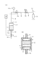
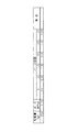
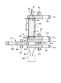
図1は、本発明の粉粒状物に対するガス置換方法を実施するための装置を示すシステム図と部分的な断面図である。 FIG. 1 is a system diagram and a partial cross-sectional view showing an apparatus for carrying out a gas replacement method for a granular material according to the present invention.
図1(A)に示すように、この実施例で取扱われる粉粒状物は、小麦粉1である。そして、同図(B)に示すように、上記小麦粉1を収容する密閉容器2は、円筒状の形状とされ、上蓋3と下蓋4を上下に嵌合することにより、密閉容器としての構造が形成されている。上記上蓋3には薄板状のフィルタ5を取り付けることにより拡散室6が設けられている。同様の構造により、下蓋4にもフィルタ7を取り付けることにより拡散室8が設けられている。なお、フィルタ5,7は、小麦粉1の通過を阻止できるメッシュの小さな合成樹脂製網で形成されている。この合成樹脂としてはポリアミド樹脂が使用されている。しかし、他のフィルタ材を用いてもよい。また、密閉容器2内には、250gの小麦粉1が充填され、この充填量は密閉容器2の容量の約70%である。
As shown in FIG. 1 (A), the granular material handled in this example is
上記拡散室3には、不活性ガスである窒素ガスを密閉容器2内に供給する供給管9が接続されている。同様の構造により、拡散室8にも放出管10が接続されている。
A
図1(A)に示すように、上記窒素ガスは、ガス供給設備11から圧送される。この例では、ガス供給設備11は上記供給管9が接続された窒素ガスボンベ12で構成されている。供給管9には、圧力調整器13が配置され、さらにその後流側に電動式の入口開閉弁14が配置されている。上記圧力調整器13によって、密閉容器2内の昇圧値が設定されるようになっている。また、上記入口開閉弁14の後流側に圧力計15が取り付けられている。
As shown in FIG. 1A, the nitrogen gas is pumped from a
一方、上記放出管10には、開閉式とされたサンプルガスの抽出口16が配置され、その後流側に電動式の出口開閉弁17が設けられ、その後流側の放出管10は、大気に開放されている。
On the other hand, the
上記入口開閉弁14が開いているときには、出口開閉弁17は閉じている。逆に、入口開閉弁14が閉じているときには、出口開閉弁17は開いている。このような両開閉弁14,17の交互開閉や開閉時間を設定し開閉動作を行うために、制御装置18が設けられている。この制御装置18は、両開閉弁14,17に動作信号を供給するものである。
When the inlet on / off
上記入口開閉弁14を開いて窒素ガスが密閉容器2へ供給されるときには、上記圧力調整器13で窒素ガスの圧力が高圧に設定され、この高圧の窒素ガスが密閉容器2内に供給され、それによって密閉容器2内が昇圧される。この昇圧された窒素ガスが密閉容器2内に供給されると、窒素ガスの圧力伝播とともに窒素ガスが小麦粉1の隅々まで侵入する。その後、入口開閉弁14を閉じてから出口開閉弁17を開くと、高圧となっている密閉容器2内の窒素ガスは放出管10を経て外部へ放出されて、密閉容器2内が脱圧される。この放出時すなわち脱圧時に、小麦粉1内に存在している空気が、同時に放出される。
When the inlet opening / closing
なお、上記の窒素ガスの供給において、供給管9から拡散室6内に流入した窒素ガスは、拡散室6の全体に広がりフィルタ5の全域を均一に通過する。したがって、小麦粉1に対する窒素ガスの圧力伝播ないしは小麦粉1内への侵入が、小麦粉1の特定の箇所に片寄ることなく、小麦粉1全体に対して良好になされる。また、脱圧時のガス放出においては、放出側の拡散室8を経て放出管10に流出するので、小麦粉1内に残留している空気を小麦粉1の全域から均一に放出することができる。上記のように、流入側と流出側にそれぞれ拡散室6,8が配置されているので、小麦粉1内を通過する空気や窒素ガスに片寄った流れや乱流が発生することがなく、良好なガス置換がなされる。
In the supply of nitrogen gas, the nitrogen gas that has flowed into the diffusion chamber 6 from the
つぎに、図1に示したシステムによる実験結果を説明する。 Next, an experimental result by the system shown in FIG. 1 will be described.
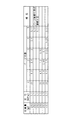
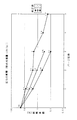
図3および図4は、小麦粉1の充填量を250gとし、上記の昇圧時の窒素ガスの圧力を0.1MPa,0.2MPa,0.3MPaの3圧力とした場合、パージ回数(昇圧・脱圧の回数)と抽出口16からサンプリングしたガス中の酸素濃度との関係を示している。すなわち、窒素ガスの昇圧値が0.1MPaでパージ回数を5回行った場合は、パージ回数ゼロ時の20%酸素濃度が0.17%に減少していることが認められた。また、5回のパージ後に密閉容器2を振って小麦粉1を振り混ぜると、酸素濃度が0.07%に低減していることが認められた。この振り混ぜにより、酸素濃度の増加が認められないので、小麦粉1の内部は、全域にわたって均一にガス置換がなされていることが明らかになった。また、この振り混ぜによる酸素濃度の低減は、密閉容器2内の空間部に存在している窒素ガスが振り混ぜ時に小麦粉1内に均一に侵入したことによるものと考えられる。
3 and 4 show that when the filling amount of
また、窒素ガスの昇圧値を0.2MPaおよび0.3MPaに上昇させると、パージ回数が3回であっても、酸素濃度が0.32%および0.1%であり、十分にガス置換がなされていることが認められた。このように窒素ガスの昇圧値を高めて行くと、小麦粉1内への窒素ガスの侵入量が増量されて、ガス置換性が向上することが認められる。
Further, when the pressure increase value of the nitrogen gas is increased to 0.2 MPa and 0.3 MPa, the oxygen concentration is 0.32% and 0.1% even if the number of purges is 3, and the gas replacement is sufficiently performed. It was recognized that it was made. It is recognized that when the pressure increase value of nitrogen gas is increased in this way, the amount of nitrogen gas entering into the
上記のように、いずれの実験例においても残留酸素濃度が0.5%を大幅に下回る結果が得られ、小麦粉1に酸化劣化等の品質異常を来さない十分な窒素ガスの置換がなされることが判明した。
As described above, in any of the experimental examples, a result in which the residual oxygen concentration is significantly lower than 0.5% is obtained, and sufficient replacement of nitrogen gas that does not cause quality abnormalities such as oxidative degradation in the
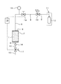
図2は、密閉容器2内に400gの小麦粉を充填して密閉容器2を満タン状態にした場合のシステム図である。図3に示すように、400g充填量で0.1MPaの窒素ガス昇圧値の場合においても、4回目のパージ回数の段階ですでに酸素濃度0.5%を大幅に下回る0.35%の値を得ることができ、250g充填の場合と同様な結果が得られた。また、図5は、小麦粉1の充填量の影響を示す線図であり、250gと400gのいずれにおいても、4回目のパージ回数の段階で良好な酸素濃度となっていることが認められた。
FIG. 2 is a system diagram when the sealed
図6は、比較実験例を示すデータである。小麦粉1の充填量は250g、窒素ガスの昇圧値は0.02MPaとし、パージ回数5回毎に抽出口16からガスサンプリングを行い酸素濃度を測定した。その結果、パージ回数が25回に及んでも酸素濃度は0.66%であり、上記のように0.5%を下回ることができなかった。このように窒素ガスの昇圧値が0.02MPaのように低くて、密閉容器2内における昇圧時と脱圧時の圧力差が小さい場合には、十分な置換効果が得られないことが明らかとなった。
FIG. 6 is data showing a comparative experimental example. The filling amount of the
昇圧時の密閉容器2内の圧力は、1MPa〜0.05MPaの範囲内に設定することが好ましく、より好ましくは0.8MPa〜0.07MPaである。さらに、より好ましいのは、0.6MPa〜0.09MPaであり、最も好ましいのは0.4MPa〜0.1MPaである。このようにすることにより、上記のように良好なガス置換が行える。そして、大掛かりな圧力発生装置を用いることなく、安価な装置で効率的にガス置換を行うことができる。すなわち、1MPaを超える圧力ではそれに耐える高圧ガス施設とする必要があり、いずれにしても設備コストやメンテナンスコストが大幅アップとなってしまうが、上記圧力範囲内で昇圧値を設定することにより、安価な装置で効率的にガス置換を行うことができるようになるのである。
The pressure in the sealed
また、昇圧時の密閉容器2内の置換ガスの圧力と、上記脱圧時の密閉容器2内の置換ガスの圧力との差は、0.05MPa以上に設定するのが好ましく、より好ましくは0.07MPa以上である。最も好ましいのは、0.09MPa以上である。上記の圧力差0.05MPa以上は、大気圧(0MPa)〜+1MPaの圧力範囲内において付与される。一方、圧力差0.05MPa以上を負圧寄りの状態で付与する場合は、−0.1MPa〜大気圧(0MPa)の圧力範囲内において付与される。
Further, the difference between the pressure of the replacement gas in the sealed
上記実施例の作用効果を列記すると、つぎのとおりである。 The effects of the above embodiment are listed as follows.
上記小麦粉1が収容された密閉容器2内に置換ガスが供給され、しかもその置換ガスによって密閉容器2内が昇圧されるので、密閉容器2内が昇圧される過渡期に密閉容器2内全域への圧力伝播とともに置換ガスが小麦粉1の隅々まで侵入する。一方、上記のようにして高圧となっている密閉容器2内の置換ガスを外部へ放出して脱圧することにより、この放出時に小麦粉1内に存在している空気が、同時に放出される。したがって、密閉容器2内の昇圧から脱圧への圧力変動により、この圧力変動に伴うガス流動が密閉容器2内に得られ、上記空気等の残留ガスが確実に置換される。とくに、密閉容器2内に対する昇圧と脱圧であるから、置換ガスが密閉容器2内を通過する現象ではなく、置換ガス流による動圧が小麦粉1に作用することがきわめて少なくなり、小麦粉1が舞い上がるようなことが防止でき、小麦粉1を略静的な状態にしたままガス置換ができる。さらに、置換ガスの昇圧と脱圧の制御であるから、制御が簡素化され、操業の行いやすい生産工程が実現する。
The replacement gas is supplied into the sealed
さらに、本発明の方法を実施するに際しての主な設備構造としては、置換ガスを密閉容器2内に供給するためのガス供給設備11と、ガスの供給流を断続する入口開閉弁14と、上記放出ガス流を断続する出口開閉弁17と、上記ガス供給設備11や開閉弁14,17を動作させる制御装置18とによって構成することができる。このような設備構造は、汎用性のあるユニット等を利用して形成できるので、設備構造が簡素化でき、設備費用の低減にも有効である。同時に、簡素化された設備により、メンテナンス周期も長期化し、信頼性の高い設備稼動が実現する。
Furthermore, the main equipment structure for carrying out the method of the present invention includes a
上記のようにして、前述の真空法,ノズル注入法およびスクリュー撹拌法等における問題点が解消される。 As described above, the problems in the vacuum method, nozzle injection method, screw stirring method and the like described above are solved.
上記密閉容器2内に置換ガスを供給する供給管9と、密閉容器2内の置換ガスを放出する放出管10とを、上記小麦粉1を挟んで略対向した位置関係とすることにより、小麦粉1内に導入された置換ガスが昇圧時に小麦粉1内に侵入して行く方向と、脱圧時に空気や置換ガスが放出されて行く方向とが同一方向となる。したがって、上記供給管9側から放出管10側に向って一方向の方向性のある置換流動状態が形成され、小麦粉1内に残留している空気が効率的に排出され、確実なガス置換が得られる。
By making the
上記昇圧と脱圧を、所定回数繰り返すことにより、残留空気の濃度を一層低減させることができて、置換ガスの充満性が一層高くなる。 By repeating the pressurization and depressurization a predetermined number of times, the concentration of residual air can be further reduced and the replacement gas can be more fully filled.
上記昇圧時の密閉容器2内の圧力が、1MPa以下であることにより、大掛かりな圧力発生装置を用いることなく、安価な装置で効率的にガス置換を行うことができる。すなわち、1MPaを超える圧力ではそれに耐える高圧ガス施設とする必要があり、いずれにしても設備コストやメンテナンスコストが大幅アップとなってしまうが、上記圧力範囲内で昇圧をさせることにより、安価な装置で効率的にガス置換を行うことができるようになるのである。
Since the pressure in the sealed
上記昇圧時の密閉容器2内の置換ガスの圧力と、上記脱圧時の密閉容器2内の置換ガスの圧力との差が、0.05MPa以上であるから、昇圧時における置換ガスの小麦粉1内への侵入と、脱圧時における置換ガスの小麦粉1外への排出とが確実に行われ、短時間で効率的なガス置換を行うことができる。さらに、大掛かりな圧力発生装置を用いることなく、安価な装置で効率的にガス置換を行うことができる。
Since the difference between the pressure of the replacement gas in the sealed
さらに、何等かの原因で小麦粉1が片寄った箇所に固まった場合には、ガス流を逆にして、固まりを砕くことも可能である。
In addition, when the
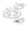
図7,図8および図9は、本発明の粉粒状物に対するガス置換方法の第2の実施例を示すもので、各図は本発明の方法を実施するガス置換装置の構造を示している。 7, 8 and 9 show a second embodiment of the gas replacement method for the granular material of the present invention, and each figure shows the structure of the gas replacement apparatus for performing the method of the present invention. .
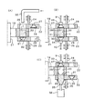
図7は概念的な分解斜視図、図8は装置の動作順序を示す断面図、図9は小麦粉の袋を封止する状態を示す断面図である。小麦粉1の量を計量する計量円盤19には、複数の計量穴20が同心円状に設けられている。上記計量円盤19の中心には、回転軸21が取り付けられ、この回転軸21は、ガス置換装置の静止部材に設けた軸受(図示していない)に支持されている。また、駆動装置(図示していない)によって計量円盤19が回転するようになっている。
7 is a conceptual exploded perspective view, FIG. 8 is a cross-sectional view showing an operation sequence of the apparatus, and FIG. 9 is a cross-sectional view showing a state in which a bag of flour is sealed. A measuring
計量円盤19の上面に摺動しながら回転する入口側回転板22と、計量円盤19の下面に摺動しながら回転する出口側回転板23とが、計量円盤19を挟んだ位置関係で配置されている。両回転板22,23の回転軸24,25は同軸の状態とされ、しかも計量円盤19の回転軸21と平行になっている。また、両回転軸24,25は、別々の駆動装置(図示していない)によって駆動され、異なった回転動作をするようになっている。
An inlet-
上記入口側回転板22には、小麦粉1の入口穴26と窒素ガスの供給穴27が180度間隔で設けられている。上記供給穴27の下部にフィルタ28が取り付けてある。一方、出口側回転板23には、小麦粉1の出口穴29と窒素ガスの放出穴30が180度間隔で設けられている。上記放出穴30の上部にフィルタ31が取り付けてある。また、小麦粉1の供給管32が入口穴26の上方に位置するように配置されている。
The inlet
図8(A)は、入口側回転板22と出口側回転板23の回転停止位置が所定の位置に設定され、それによって、入口穴26,計量穴20,放出穴30が一直線上に配列された状態を示している。他方、この状態においては、入口側回転板22の供給穴27と出口側回転板23の出口穴29が一直線上に配列されている。図8(A)は、供給管32から計量穴20内に小麦粉1が供給された状態である。
In FIG. 8A, the rotation stop positions of the inlet
上記(A)の状態から入口側回転板22だけが回転して所定位置に停止した状態が(B)に示されている。この状態では、計量穴20にフィルタ28が合致して、小麦粉1は上記の密閉容器2内に収容された状態と同じ状態になっている。この状態における供給穴27と放出穴30に対して、供給管9の接手部材33と放出管10の接手部材34が気密を保った状態で密着する。その後、窒素ガスの昇圧と脱圧とが上記実施例と同様にして行われ、小麦粉1内の空気が窒素ガスに置換される。
(B) shows a state in which only the entrance-
(C)は、ガス置換が終了した小麦粉1を取り出す状態を示している。すなわち、放出管10の接手部材34が後退して小麦粉1の受けダクト35が計量穴20の真下に待機し、その状態において出口側回転盤23だけが回転して、その出口穴29が計量穴20に合致する。この状態で小麦粉1は受けダクト35から袋36内に充填される。なお、このように袋36内に小麦粉1が移される過渡期に空気が混入することを防止するために、必要であれば、供給管9から窒素ガスを送り続けることが好ましい。また、袋36は、後述のヒートシールを行うために、合成樹脂や合成樹脂ラミネート紙から形成されたものが用いられる。
(C) has shown the state which takes out the
図9は、袋36をシールする装置の一例を示す断面図である。出口側回転板23の出口穴29の真下にケーシング37が待機させてある。このケーシング37の上縁にゴム等で作られた気密保持用のシール38が取り付けられ、このシール38が出口側回転板23の下面に密着できるようになっている。ケーシング37内には上記袋36が開口した状態で入れてある。
FIG. 9 is a cross-sectional view showing an example of an apparatus for sealing the
上記ケーシング37には、ケーシング37内部に存在する袋36の上部開口をヒートシールするためのヒートシーラー39が設けられている。このヒートシーラー39は、ケーシング37の上部寄りの空間に相対向するように突出し、ケーシング37の内部に進退するようになっている。また、ケーシング37には、窒素ガスの送給パイプ40と送出パイプ41が接続され、ケーシング37内を窒素ガス雰囲気にするようになっている。それ以外は、上記実施例と同様であり、同様の部分には同じ符号を付している。
The
袋36内に小麦粉1が充填されると、送給パイプ40からの窒素ガスの導入を続けてケーシング37の内部空間に空気が侵入するのを防止した状態で、上記ヒートシーラー39をケーシング37の内部に押し込むことが行われる。そして、ヒートシーラー39により袋36の上部を挟んで突き合わせ、その挟持部分を加熱することにより、図9に2点鎖線で示すように、袋36の上部開口を熱シールで封止することが行われる。このようにケーシング37内を窒素ガス雰囲気にしたままヒートシールを行うことにより、窒素ガスに置換された小麦粉1内に空気が混入することが完全に防止でき、ガス置換が一層高レベルで行われる。それ以外は、上記実施例と同様の作用効果を奏する。
When the
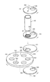
図10および図11は、本発明の粉粒状物に対するガス置換方法の第3の実施例を示すもので、各図は本発明の方法を実施するガス置換装置およびガス置換後の小麦粉1を計量する計量装置の構造を示している。
FIG. 10 and FIG. 11 show a third embodiment of the gas replacement method for the granular material of the present invention, and each figure measures the gas replacement apparatus for performing the method of the present invention and the
図10は、概念的な分解斜視図、図11は、断面図である。ガス置換装置そのものは、置換室パイプ45や接手部材34を除く部分は、図8に示した実施例と同様であり、同様の部分には同じ符号を付している。上記置換室パイプ45は、上記筒状の密閉容器2に相当するもので、装置の静止部材46に結合されている。置換室パイプ45内には、小麦粉1が充填されており、その量は、複数の袋36に充填でき、しかも、ガス置換可能な範囲内で大量に充填されている。また、上記接手部材34は、出口側回転板23の外周面に合致するようになっている。
FIG. 10 is a conceptual exploded perspective view, and FIG. 11 is a cross-sectional view. The gas replacement device itself is the same as the embodiment shown in FIG. 8 except for the
上記ガス置換装置に計量装置47が組み付けられている。この計量装置47は、回転軸48を中心にして回転する計量回転板49に複数の計量穴50が1円周上に設けられ、これらの計量穴50を開閉する第1回転板51と第2回転板52が設けられている。上記計量穴50は、小麦粉1を所定の量に計量できるように所定の容積に設定され、複数の計量量を得るために計量穴50の大きさを変えることができる。上記両回転板51,52はそれぞれ回転軸53,54に支持されて回転するようになっている。第1回転板51の上面は、ガス置換装置の出口側回転板23の下面に密着しているとともに、その下面は計量回転板49の上面に密着した状態で回転できるようになっている。
A
第1回転板51には、小麦粉1を計量穴50に導く導入穴55が、第1回転板51を貫通した状態で形成されている。また、第2回転板52には、計量された計量穴50内の小麦粉1を受けダクト35へ送り出す送出穴56が、第2回転板52を貫通した状態で形成されている。上記回転軸25,53,54は同軸上に配置され、図11に示すように、出口穴29と導入穴55と送出穴56は同じ直径とされ、同一円周上に設けられている。また、後述のように、導入穴55と送出穴56は、第1回転板51と第2回転板52が回転することによって、計量回転板49の計量穴50に合致できる箇所に配置されている。
In the first
上記計量装置47の動作を説明する。図11は、ガス置換装置が窒素ガスの昇圧と脱圧を繰り返してガス置換動作をしている状態を示す。そして、計量装置47は、計量穴50の上下いずれをも閉じている状態である。
The operation of the weighing
上記ガス置換が終了すると、接手部材34が出口側回転板23から離れ、ついで出口側回転板23と第1回転板51とが共に回転して、出口穴29と導入穴55とが合致したまま置換室パイプ45に連通する。これにより、小麦粉1は計量穴50内に充満し、その状態で第1回転板51が回転して計量穴50を閉じると、小麦粉1が計量穴50に封じ込まれて計量される。その後、第2回転板52が回転して計量穴50に送出穴56が合致すると、小麦粉1は受けダクト35を経て袋36内に充填される。最後に袋36は、ヒートシーラー(例えば、図9に示すようなヒートシーラー39)でシールされて空気の侵入が遮断される。
When the gas replacement is completed, the
上記構成により、窒素ガスに置換された小麦粉1が、計量装置47において連続的に計量されるので、空気が侵入できない状態で計量をすることができる。また、ガス置換装置と計量装置47とが一体的に形成できるので、装置全体がコンパクトになり原価低減の面においても有利である。それ以外は、上記各実施例と同様の作用効果を奏する。
According to the above configuration, the
図12および図13は、本発明の粉粒状物に対するガス置換方法の第4の実施例を示すもので、各図は本発明の方法を実施するガス置換装置の構造を示している。 12 and 13 show a fourth embodiment of the gas replacement method for the granular material of the present invention, and each figure shows the structure of the gas replacement apparatus for performing the method of the present invention.
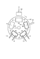
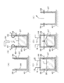
この実施例は、回転テーブル式のガス置換装置の場合である。図12は、同装置の平面図、図13は工程順序を示す断面図である。工程(A)は、回転テーブル42上に載置された上記密閉容器2に相当するケーシング37内に袋36が挿入される工程である。それから回転テーブル42が時計方向に所定角度回転して工程(B)の位置に停止し、袋36に小麦粉1が充填される。工程(B)では、図13(B)に示すように、袋36の開口を広げる開口器43が動作している。その後、各工程毎に回転テーブル42が所定角度回転して行く。工程(C)では、ケーシング37の上部開口が、供給管9と放出管10が開口した状態で接合された蓋部材44で閉じられ、ケーシング37内が窒素ガスで昇圧され、その後脱圧されてガス置換が行われる。工程(D)において袋36がヒートシールされる。そして、工程(E)で袋36が取り出される。なお、ケーシング37を回転テーブル42上に保持する方法は種々なものが採用できるが、例えば、クランプ機構(図示していない)で保持することができる。それ以外は、上記各実施例と同様であり、同様の部分には同じ符号を付している。
This embodiment is a case of a rotary table type gas displacement device. FIG. 12 is a plan view of the apparatus, and FIG. 13 is a cross-sectional view showing a process sequence. Step (A) is a step in which the
上記構成により、回転テーブル式であることにより、例えば、(A)袋の供給工程,(B)小麦粉1の充填工程,(C)窒素ガスの置換工程,(D)シーリング工程,(E)袋36の取り出し工程等の一連の工程を連続的に行う自動ラインにおいて、確実なガス置換を行うことができ、装置自体が簡素化しメンテナンス周期も長期化することができる。また、回転テーブル式の移動手段の中に、昇圧と脱圧によるガス置換工程が組み込まれているので、ガス置換に要する時間が短くて済み、製造タクトタイムの延長も防止され、生産性を低下させることがないため、効果的である。
With the above configuration, for example, (A) bag supply process, (B)
さらに、上記ケーシング37内に窒素ガスを供給する箇所と、ケーシング37内のガスを放出する箇所とを、ケーシング37の一側に配置してあるので、ケーシング37の一側から窒素ガスの供給と放出が行えて、ガス置換装置の配管が行いやすくなり、装置の簡素化ができる。それ以外は、上記各実施例と同様の作用効果を奏する。
Furthermore, since the location where the nitrogen gas is supplied into the
なお、上記第4の実施例は回転テーブル式のガス置換装置であるが、上記工程(A)〜(E)を直線的に移動するコンベア(図示していない)上にケーシング37を載置して各工程を遂行することが可能である。
Although the fourth embodiment is a rotary table type gas displacement device, a
なお、上記各実施例では、容器として、主に袋36を使用した例を示したが、これに限定するものではなく、プラスチック容器や金属容器等を使用することも可能である。また、本発明が適用される粉粒状物としては、上記実施例では小麦粉等の粉体を例示して説明したが、これに限定するものではなく、顆粒状や繊維状のものも本発明の粉粒状物に含まれる趣旨である。また、食品や薬剤,化粧品等の粉粒状製品に限定するものではなく、樹脂粉や金属粉等の工業基礎製品や半製品等、おおよそ粉粒状を呈したものであれば各種のものに適用することができる。
In each of the above embodiments, the
本発明は、上述したように、食品等の粉粒状物が酸化変質するのを防止するためのガス置換に適用することができるが、これに限定するものではなく、粉粒状物と特定のガスとの反応を促進させるためのガス置換に適用することも可能である。 As described above, the present invention can be applied to gas replacement for preventing oxidative deterioration of granular materials such as foods, but is not limited thereto, and the granular materials and specific gas are not limited thereto. It is also possible to apply to gas replacement for promoting the reaction with.
1 小麦粉
2 密閉容器
3 上蓋
4 下蓋
5 フィルタ
6 拡散室
7 フィルタ
8 拡散室
9 供給管
10 放出管
11 ガス供給設備
12 窒素ガスボンベ
13 圧力調整器
14 入口開閉弁
15 圧力計
16 抽出口
17 出口開閉弁
18 制御装置
19 計量円盤
20 計量穴
21 回転軸
22 入口側回転板
23 出口側回転板
24 回転軸
25 回転軸
26 入口穴
27 供給穴
28 フィルタ
29 出口穴
30 放出穴
31 フィルタ
32 供給管
33 接手部材
34 接手部材
35 受けダクト
36 袋
37 ケーシング
38 シール
39 ヒートシーラー
40 送給パイプ
41 送出パイプ
42 回転テーブル
43 開口器
44 蓋部材
45 置換室パイプ
46 静止部材
47 計量装置
48 回転軸
49 計量回転板
50 計量穴
51 第1回転板
52 第2回転板
53 回転軸
54 回転軸
55 導入穴
56 送出穴
DESCRIPTION OF
Claims (7)
Priority Applications (1)
| Application Number | Priority Date | Filing Date | Title |
|---|---|---|---|
| JP2004120202A JP4602687B2 (en) | 2004-04-15 | 2004-04-15 | Gas replacement method for granular materials |
Applications Claiming Priority (1)
| Application Number | Priority Date | Filing Date | Title |
|---|---|---|---|
| JP2004120202A JP4602687B2 (en) | 2004-04-15 | 2004-04-15 | Gas replacement method for granular materials |
Publications (2)
| Publication Number | Publication Date |
|---|---|
| JP2005298041A true JP2005298041A (en) | 2005-10-27 |
| JP4602687B2 JP4602687B2 (en) | 2010-12-22 |
Family
ID=35330065
Family Applications (1)
| Application Number | Title | Priority Date | Filing Date |
|---|---|---|---|
| JP2004120202A Expired - Fee Related JP4602687B2 (en) | 2004-04-15 | 2004-04-15 | Gas replacement method for granular materials |
Country Status (1)
| Country | Link |
|---|---|
| JP (1) | JP4602687B2 (en) |
Cited By (1)
| Publication number | Priority date | Publication date | Assignee | Title |
|---|---|---|---|---|
| JP2014111967A (en) * | 2012-12-05 | 2014-06-19 | Osaka Gas Co Ltd | Purge method of gas piping |
Citations (2)
| Publication number | Priority date | Publication date | Assignee | Title |
|---|---|---|---|---|
| JPH0369416A (en) * | 1989-07-28 | 1991-03-25 | Nippon Kayaku Co Ltd | Method for adjusting packing density of packed explosive |
| JPH09509386A (en) * | 1993-12-08 | 1997-09-22 | フィリップ パトゥロ, | Method for deactivating packaging cover, apparatus therefor and packaging cover used for the method |
-
2004
- 2004-04-15 JP JP2004120202A patent/JP4602687B2/en not_active Expired - Fee Related
Patent Citations (2)
| Publication number | Priority date | Publication date | Assignee | Title |
|---|---|---|---|---|
| JPH0369416A (en) * | 1989-07-28 | 1991-03-25 | Nippon Kayaku Co Ltd | Method for adjusting packing density of packed explosive |
| JPH09509386A (en) * | 1993-12-08 | 1997-09-22 | フィリップ パトゥロ, | Method for deactivating packaging cover, apparatus therefor and packaging cover used for the method |
Cited By (1)
| Publication number | Priority date | Publication date | Assignee | Title |
|---|---|---|---|---|
| JP2014111967A (en) * | 2012-12-05 | 2014-06-19 | Osaka Gas Co Ltd | Purge method of gas piping |
Also Published As
| Publication number | Publication date |
|---|---|
| JP4602687B2 (en) | 2010-12-22 |
Similar Documents
| Publication | Publication Date | Title |
|---|---|---|
| EP2054304B1 (en) | Package with an element for the controlled change of the gas content inside the package | |
| WO2024027324A1 (en) | Full-automatic flavor compounding machine | |
| JP4602687B2 (en) | Gas replacement method for granular materials | |
| EP2125522B1 (en) | Method and apparatus for compacting flowable solids | |
| EP2928800B1 (en) | Apparatus and method for transferring and pressurizing powder | |
| WO2023202832A1 (en) | Method and apparatus for filling an open container | |
| WO2007019226A2 (en) | High throughput mechanical alloying and screening | |
| CN218877649U (en) | A powder pesticide quantitative filling machine | |
| JP2549273B2 (en) | Deaeration device for powder filling machine | |
| US6796107B2 (en) | Method and apparatus for packaging ultra fine powders into containers | |
| JP4511155B2 (en) | Gas replacement method and apparatus for granular materials | |
| JP2772561B2 (en) | Continuous high-pressure transport equipment | |
| JP4922598B2 (en) | Powder discharging device | |
| CN112317745B (en) | Automatic additive manufacturing powder storage device and storage method | |
| CN113002818A (en) | Material stopping device, metering control method and packaging machine | |
| CN202783873U (en) | Nitrogen-filled packing control system | |
| CN209192392U (en) | A kind of opening packing machine | |
| JP2004210388A (en) | Deaeration filling apparatus for powder and granule substance | |
| US7320344B2 (en) | Device for compacting a flowable solid material | |
| KR20250054932A (en) | Apparatus for manufacturing standard gas in oil | |
| CN103523270A (en) | Nitrogen-filled packing control system | |
| CN116494414A (en) | a batching system | |
| HK1125607B (en) | Package with an element for the controlled change of the gas content inside the package | |
| CN106591099A (en) | Feeding and discharging device and method |
Legal Events
| Date | Code | Title | Description |
|---|---|---|---|
| A621 | Written request for application examination |
Free format text: JAPANESE INTERMEDIATE CODE: A621 Effective date: 20070306 |
|
| A977 | Report on retrieval |
Free format text: JAPANESE INTERMEDIATE CODE: A971007 Effective date: 20100315 |
|
| A131 | Notification of reasons for refusal |
Free format text: JAPANESE INTERMEDIATE CODE: A131 Effective date: 20100323 |
|
| A521 | Written amendment |
Free format text: JAPANESE INTERMEDIATE CODE: A523 Effective date: 20100511 |
|
| TRDD | Decision of grant or rejection written | ||
| A01 | Written decision to grant a patent or to grant a registration (utility model) |
Free format text: JAPANESE INTERMEDIATE CODE: A01 Effective date: 20100928 |
|
| A01 | Written decision to grant a patent or to grant a registration (utility model) |
Free format text: JAPANESE INTERMEDIATE CODE: A01 |
|
| A61 | First payment of annual fees (during grant procedure) |
Free format text: JAPANESE INTERMEDIATE CODE: A61 Effective date: 20100930 |
|
| FPAY | Renewal fee payment (event date is renewal date of database) |
Free format text: PAYMENT UNTIL: 20131008 Year of fee payment: 3 |
|
| R150 | Certificate of patent or registration of utility model |
Ref document number: 4602687 Country of ref document: JP Free format text: JAPANESE INTERMEDIATE CODE: R150 Free format text: JAPANESE INTERMEDIATE CODE: R150 |
|
| R250 | Receipt of annual fees |
Free format text: JAPANESE INTERMEDIATE CODE: R250 |
|
| R250 | Receipt of annual fees |
Free format text: JAPANESE INTERMEDIATE CODE: R250 |
|
| R250 | Receipt of annual fees |
Free format text: JAPANESE INTERMEDIATE CODE: R250 |
|
| R250 | Receipt of annual fees |
Free format text: JAPANESE INTERMEDIATE CODE: R250 |
|
| R250 | Receipt of annual fees |
Free format text: JAPANESE INTERMEDIATE CODE: R250 |
|
| R250 | Receipt of annual fees |
Free format text: JAPANESE INTERMEDIATE CODE: R250 |
|
| LAPS | Cancellation because of no payment of annual fees |