JP2005297956A - Drink holder - Google Patents
Drink holder Download PDFInfo
- Publication number
- JP2005297956A JP2005297956A JP2005112134A JP2005112134A JP2005297956A JP 2005297956 A JP2005297956 A JP 2005297956A JP 2005112134 A JP2005112134 A JP 2005112134A JP 2005112134 A JP2005112134 A JP 2005112134A JP 2005297956 A JP2005297956 A JP 2005297956A
- Authority
- JP
- Japan
- Prior art keywords
- holding
- drink holder
- drink
- ring
- retaining ring
- Prior art date
- Legal status (The legal status is an assumption and is not a legal conclusion. Google has not performed a legal analysis and makes no representation as to the accuracy of the status listed.)
- Pending
Links
- 230000008878 coupling Effects 0.000 claims description 3
- 238000010168 coupling process Methods 0.000 claims description 3
- 238000005859 coupling reaction Methods 0.000 claims description 3
- 210000002105 tongue Anatomy 0.000 description 10
- 230000000295 complement effect Effects 0.000 description 1
- 238000012423 maintenance Methods 0.000 description 1
- 230000002093 peripheral effect Effects 0.000 description 1
- 230000000717 retained effect Effects 0.000 description 1
Images


Classifications
-
- B—PERFORMING OPERATIONS; TRANSPORTING
- B60—VEHICLES IN GENERAL
- B60N—SEATS SPECIALLY ADAPTED FOR VEHICLES; VEHICLE PASSENGER ACCOMMODATION NOT OTHERWISE PROVIDED FOR
- B60N3/00—Arrangements or adaptations of other passenger fittings, not otherwise provided for
- B60N3/10—Arrangements or adaptations of other passenger fittings, not otherwise provided for of receptacles for food or beverages, e.g. refrigerated
- B60N3/105—Arrangements or adaptations of other passenger fittings, not otherwise provided for of receptacles for food or beverages, e.g. refrigerated for receptables of different size or shape
-
- B—PERFORMING OPERATIONS; TRANSPORTING
- B60—VEHICLES IN GENERAL
- B60N—SEATS SPECIALLY ADAPTED FOR VEHICLES; VEHICLE PASSENGER ACCOMMODATION NOT OTHERWISE PROVIDED FOR
- B60N3/00—Arrangements or adaptations of other passenger fittings, not otherwise provided for
- B60N3/10—Arrangements or adaptations of other passenger fittings, not otherwise provided for of receptacles for food or beverages, e.g. refrigerated
- B60N3/102—Arrangements or adaptations of other passenger fittings, not otherwise provided for of receptacles for food or beverages, e.g. refrigerated storable or foldable in a non-use position
Landscapes
- Engineering & Computer Science (AREA)
- Physics & Mathematics (AREA)
- Thermal Sciences (AREA)
- Transportation (AREA)
- Mechanical Engineering (AREA)
- Passenger Equipment (AREA)
- Finger-Pressure Massage (AREA)
- Table Devices Or Equipment (AREA)
- Holding Or Fastening Of Disk On Rotational Shaft (AREA)
- Details Of Rigid Or Semi-Rigid Containers (AREA)
Abstract
【課題】多面的に利用可能なドリンクホルダを提供する。
【解決手段】ドリンクホルダであって、ドリンク容器を収容するための上方で開かれた収容部と、保持リングとが設けられており、該保持リングは基本位置で収容部の上縁部に位置しており、保持リングを第1保持位置にもたらすことができ、該第1保持位置では保持リングは側方で収容部の上方に位置している形式のものにおいて、
保持リング(16)を第2保持位置にもたらすことができ、該第2保持位置では保持リングは収容部(14)の上方に位置していて、収容部(14)に対して側方にずらされていない。
【選択図】図4A drink holder that can be used in many ways is provided.
A drink holder is provided with a holding portion opened above for holding a drink container, and a holding ring, and the holding ring is positioned at the upper edge of the receiving portion at a basic position. The retaining ring can be brought into the first holding position, in which the holding ring is laterally located above the receiving part,
The retaining ring (16) can be brought into a second retaining position, in which the retaining ring is located above the receiving part (14) and is shifted laterally with respect to the receiving part (14). It has not been.
[Selection] Figure 4
Description
本発明は、ドリンクホルダであって、ドリンク容器を収容するための上方で開かれた収容部と、保持リングとが設けられており、該保持リングは基本位置で収容部の上縁部に位置しており、保持リングを第1保持位置にもたらすことができ、該第1保持位置では保持リングは側方で収容部の上方に位置している形式のものに関する。 The present invention is a drink holder, and is provided with a storage portion opened above for storing a drink container, and a holding ring, and the holding ring is positioned at the upper edge of the storage portion at a basic position. The retaining ring can be brought into a first holding position, in which the holding ring is laterally located above the receiving part.
このような形式のドリンクホルダは公知であり、1つまたは2つのドリンク容器を自動車において保持するために用いられる。ドリンク容器は、ドリンク缶、カップ、コップ等であって良い。ドイツ連邦共和国特許第4429515号明細書により2つのドリンク容器のためのドリンクホルダが公知である。この公知のドリンクホルダは、ドリンク容器を収容するための収容部として円筒状の1つの凹部を有している。さらに公知のドリンクホルダは、折り畳み可能な2つの保持アームから成る1つの保持リングを有している。スライドガイドにより、保持リングは上方に向かって摺動可能であって、側方に向かって1つの保持位置へと旋回可能である。この保持位置では、保持リングが収容部の上方で、収容部に対して側方にずらされて位置している。基本位置では、(折り畳まれた)保持リングが収容部内に位置していて、この収容部は使用できない。 Such types of drink holders are known and are used to hold one or two drink containers in a motor vehicle. The drink container may be a drink can, a cup, a cup or the like. A drink holder for two drink containers is known from DE 44 29 515 A1. This known drink holder has one cylindrical recess as an accommodating portion for accommodating a drink container. Furthermore, the known drink holder has one holding ring consisting of two folding holding arms. By means of the slide guide, the holding ring can slide upwards and can turn sideways to one holding position. In this holding position, the holding ring is positioned above the housing portion and shifted laterally with respect to the housing portion. In the basic position, the (folded) retaining ring is located in the receiving part and cannot be used.
本発明の課題は、多面的に利用可能なドリンクホルダを提供することである。 An object of the present invention is to provide a drink holder that can be used in many ways.
この課題を解決するために本発明の構成では、保持リングを第2保持位置にもたらすことができ、該第2保持位置では保持リングは収容部の上方に位置していて、収容部に対して側方にずらされていないようにした。 In order to solve this problem, in the configuration of the present invention, the holding ring can be brought to the second holding position, and in the second holding position, the holding ring is located above the receiving portion and It was not shifted to the side.
本発明によるドリンクホルダは、ドリンク容器を収容するための上方で開かれた収容部を有している。この場合、「上方」とはドリンクホルダの所定の取付位置に関する。収容部は例えば円筒状の凹部であって良い。さらに本発明によるドリンクホルダは、基本位置で収容部の上縁部に位置する保持リングを有している。この保持リングは、この場合、収容部へのドリンク容器の収容および取り出しを妨げない。保持リングは閉じられている必要はなく、保持リングが収容されたドリンク容器を、ドリンク容器が全ての方向で側方で保持されるように取り囲み側方で支持していれば十分である。基本位置では、保持リングは機能を有しておらず、省スペース的に取り付けられている。ドイツ連邦共和国特許第4429515号明細書により公知のドリンクホルダとは異なり、本発明によるドリンクホルダは、保持リングが基本位置にある場合もドリンク容器を収容するために使用可能である。 The drink holder by this invention has the accommodating part opened upwards for accommodating a drink container. In this case, “upward” relates to a predetermined mounting position of the drink holder. The accommodating part may be, for example, a cylindrical concave part. Furthermore, the drink holder by this invention has the holding ring located in the upper edge part of an accommodating part in a basic position. In this case, the holding ring does not prevent the drink container from being stored in and taken out from the storage unit. The retaining ring does not have to be closed, it is sufficient if the drink container in which the retaining ring is accommodated is supported by the surrounding sides so that the drink container is retained laterally in all directions. In the basic position, the retaining ring has no function and is mounted in a space-saving manner. Unlike the drink holders known from DE 44 29 515 A1, the drink holder according to the invention can be used to accommodate drink containers even when the retaining ring is in the basic position.
本発明によるドリンクホルダの保持リングは、側方で収容部の上方に位置する第1保持位置にもたらすことができる。第1保持位置では、1つのドリンク容器はドリンクホルダの収容部に収容可能であって、第2のドリンク容器をその側方(かつ上方)お保持リングに収容可能である。このように、本発明によるドリンクホルダは2つのドリンク容器を保持するために適している。 The holding ring of the drink holder according to the invention can be brought to a first holding position located laterally above the receiving part. In the first holding position, one drink container can be stored in the storage portion of the drink holder, and the second drink container can be stored in the side (and upper) holding ring. Thus, the drink holder according to the invention is suitable for holding two drink containers.
さらに本発明によるドリンクホルダの保持リングは第2保持位置にもたらすことができる。第2保持位置では、保持リングはドリンク容器を収容するための収容部の上方に位置しているが、収容部の側方にはずらされておらず、収容部に整合している、またはほぼ整合している。保持リングの第2保持位置では、ドリンク容器はドリンクホルダ内に収容可能であって、ドリンク容器は保持リングによって収容部に収容される。収容部の上方に位置する保持リングは、収容されたドリンクホルダを比較的高い高さで保持している。これにより、本発明によるドリンクホルダは、例えば収容部では十分傾動しないようには保持されないボトルのような嵩高のドリンク容器を収容するのに適している。 Furthermore, the holding ring of the drink holder according to the invention can be brought to the second holding position. In the second holding position, the holding ring is located above the receiving part for containing the drink container, but is not shifted to the side of the receiving part and is aligned with the receiving part or substantially Consistent. In the second holding position of the retaining ring, the drink container can be accommodated in the drink holder, and the drink container is accommodated in the accommodating portion by the retaining ring. The holding ring located above the storage unit holds the stored drink holder at a relatively high height. Thereby, the drink holder by this invention is suitable for accommodating a bulky drink container like a bottle which is not hold | maintained, for example so that it may not tilt enough in an accommodating part.
本発明によるドリンクホルダは、1つだけのドリンク容器を保持するためのドリンクホルダのために必要な構成スペースに取付可能であるという利点を有している。この場合、本発明によるドリンクホルダは、1つのまたは2つのドリンク容器を選択的に保持するために、または1つの嵩高のドリンク容器を保持するために適している。このような嵩高のドリンク容器は、第2保持位置に位置する保持リングによって比較的高い高さで側方から支持される。 The drink holder according to the invention has the advantage that it can be mounted in the required configuration space for a drink holder for holding only one drink container. In this case, the drink holder according to the invention is suitable for selectively holding one or two drink containers or for holding one bulky drink container. Such a bulky drink container is supported from the side at a relatively high height by a holding ring located at the second holding position.
本発明の構成では、保持リングを上方に向かって摺動可能に案内するスライドガイドが設けられている。このような形式のスライドガイドは種々様々な構成が公知であり、例えばテレスコピック式ガイドも適している。 In the structure of this invention, the slide guide which guides a holding | maintenance ring so that sliding is possible upwards is provided. Various types of slide guides of this type are known, and for example, a telescopic guide is also suitable.
本発明の構成では、保持リングを側方へと旋回可能にガイドする旋回軸受が設けられている。別の構成では、水平の旋回軸線を有した旋回軸受が設けられている。即ち、一方の保持位置では保持リングの一方の端面が、他方の保持位置では保持リングの他方の端面が上方に位置している。旋回軸受により保持リングを簡単に側方へと運動可能に案内することができる。 In the configuration of the present invention, a slewing bearing that guides the holding ring so as to be pivotable to the side is provided. In another configuration, a slewing bearing with a horizontal slewing axis is provided. That is, one end surface of the holding ring is positioned at one holding position, and the other end surface of the holding ring is positioned above at the other holding position. The slewing bearing can easily guide the holding ring so that it can move laterally.
本発明の構成では、保持リングのための解離可能な結合体が設けられている。基本位置ではドリンクホルダの収容部の上縁部に位置する保持リングが解離可能に、ドリンクホルダにおいて収容部の上方に固定可能である。この場合固定は、第1保持位置においては収容部に対して側方でずらされていて、第2保持位置においては収容部に対して整合して、またはほぼ整合して行うことができる。本発明のこのような構成により、最も単純な場合には2つの部分を備えたドリンクホルダの簡単な構成が得られる。即ち収容部自体と、第2の部分として保持リングとを有したドリンクホルダである。 In the arrangement of the invention, a releasable coupling for the retaining ring is provided. In the basic position, the holding ring located at the upper edge of the drink holder accommodating portion can be disengaged and can be fixed above the accommodating portion in the drink holder. In this case, the fixing can be performed laterally with respect to the housing portion at the first holding position, and can be aligned or substantially aligned with the housing portion at the second holding position. Such a configuration of the present invention provides a simple configuration of a drink holder with two parts in the simplest case. That is, it is a drink holder having the housing part itself and a holding ring as the second part.
次に図面につき本発明の実施例を詳しく説明する。 Embodiments of the present invention will now be described in detail with reference to the drawings.
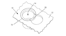
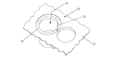
図1〜図3に示した本発明によるドリンクホルダ10は、図示されていない自動車のセンターコンソール12(図面にはその一部のみを示す)に組み込まれている。ドリンクホルダ10は円筒状の凹部を有しており、該凹部は、例えばドリンク缶、コップ、カップのようなドリンク容器を収容するための収容部14を形成する。さらにドリンクホルダ10は保持リング16を有しており、この保持リング16は図1に示した基本位置において、収容部14の上縁部に配置されている。本発明の図示した実施例では、保持リング16はその基本位置において、収容部14の上縁部に設けられた収容部14の環状段部状の拡大部18に挿入されており(図2および図3参照)、保持リング16はセンターコンソール12と同一平面を成すように収容部14内に沈められている。保持リング16は図示されていない旋回軸受でスライダ20の上端部に旋回可能に支承されている。スライダ20はプレート状で収容部14の直径に相応して湾曲されている。スライダ20は収容部14の周面に設けられた切欠内に配置されている。スライダ20はスライダガイド22によって鉛直方向で摺動可能にドリンクホルダ10内に案内されており、スライダガイド22は溝・キーガイドとして形成されている。図1に示した基本位置では、スライダ20はセンターコンソール12内に沈められていて、上方でセンターコンソール12と同一平面を成している。
The
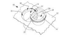
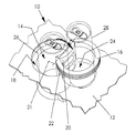
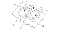
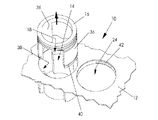
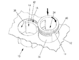
スライダ20の上方に向かう摺動により、保持リング16は保持位置にもたらされる。この保持位置では保持リング16は収容部14の上方に位置している。この場合、2つの保持位置がある。即ち図2に示した以下で第2保持位置と言う保持位置と、図3に示した第1保持位置である。第2保持位置では、保持リング16は収容部14に整合して収容部14の上方に位置し、第1保持位置では、保持リング16は旋回軸受の水平の旋回軸線21を中心として、スライダ20の収容部14とは反対の側に旋回されている。第1保持位置では保持リング16は収容部14の上方に位置し、側方で収容部14に対してずらされている。第1保持位置において保持リング16の下方には、収容されたドリンク容器の底部を受容するための低い円筒状の凹設部24が位置している。
The sliding toward the upper side of the
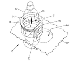
図4に示したように、保持リング16の第1保持位置ではドリンク容器、例えばドリンク缶26を収容部14に、第2のドリンク容器、例えばドリンク缶28を保持リング16に収容することができる。本発明によるドリンクホルダ10は即ち2つのドリンク容器26,28を保持することができる。図5に示したように、保持リング16の基本位置では、例えばコップ30のようなドリンク容器をドリンクホルダ10の収容部14に収容することができる。図6に示したように第2保持位置では、例えばボトル32のように比較的高いドリンク容器を保持リング16によってドリンクホルダ10の収容部14に収容することができる。収容部14の上方に位置する保持リング16は比較的高い高さでボトル32を側方から支持するので、ボトル32は傾動しないようにドリンクホルダ10に保持されている。
As shown in FIG. 4, in the first holding position of the
図7〜図9に示した本発明によるドリンクホルダ10は旋回軸受34と鉛直の旋回軸線21を有している。この旋回軸受34で保持リング16は旋回可能にスライダ20に支承もしくは案内されている。その他の点では、図7〜図9に示したドリンクホルダ10は、図1〜図6に示したドリンクホルダ10と同様に形成されていて、同様に機能する。繰り返しを避けるために、図7〜図9のドリンクホルダ10の説明は、図1〜図6のドリンクホルダ10についての上記説明を参照されたい。同じ構成部分には同じ符号付を与してある。
The
図10〜図13に示した本発明によるドリンクホルダ10は、保持リング16用の解離可能な結合体を有している。解離可能な結合体は本発明の図示した実施例ではバヨネット接続部として構成されている。その他の解離可能な結合体も可能である。
The
特に図11に示したように、ドリンクホルダ10の保持リング16は、下方に向かって突出する2つの舌片36を有している。これらの舌片36は円筒状であって、保持リング16と同じ半径を有していて、それぞれほぼ90°にわたって周方向で延びていて、互いに向かい合って配置されている。図10〜図13に示したドリンクホルダ10の収容部14は、舌片36に対して相補的な切欠38を周面に有している。図10に示した基本位置では、保持リング16は、本発明の前述した実施例の場合と同様に収容部14の上縁部における環状段部状の拡大部18に挿入されており、センターコンソール12と同一平面を成している。保持リング16の舌片36は、収容部14の切欠38内に位置している。
As shown in FIG. 11 in particular, the retaining
保持リング16を保持位置にもたらすために、保持リング16は上方に向かって収容部14から引き出されていて(図11参照)、図12および図13に示したように両保持位置にもたらされる。保持リング16のバヨネット接続部は、周方向で延びる溝40を、舌片36の、保持リング16とは反対の側の下端部に有している。この溝は、収容部14の上縁部における環状段部状の拡大部18と、収容部14の側方に位置する凹設部24とに設けられたリブ42と協働する。収容部14に設けられたリブ42は、保持リング16の舌片36のための収容部14の切欠38に対して周方向で約90°ずらされている。第1保持位置において固定するために、保持リング16の舌片36は凹設部24に挿入され、約90°回転させることにより、保持リング16の舌片36の溝40がリブ42と係合させられる。即ちバヨネット接続部40,42は閉じられ、保持リング16は第1保持位置でドリンクホルダ10に結合される。図1〜図9と同様に、図10〜図13のドリンクホルダ10の保持リング16は、図13に示した第1保持位置では、収容部14の上方で側方にずらされて、凹設部24の上方に位置している。
In order to bring the retaining
図12に示した第2保持位置では、保持リング16の舌片36の溝40は約90°の回転により収容部14のリブ42に係合する。即ちバヨネット接続部40,42が閉じられ、保持リング16は解離可能にドリンクホルダ10に結合される。保持リング16はこの第2保持位置で収容部14の上方に収容部14に整合して位置している。
In the second holding position shown in FIG. 12, the
10 ドリンクホルダ、 12 センターコンソール、 14 収容部、 16 保持リング、 18 拡大部、 20 スライダ、 21 旋回軸線、 22 スライダガイド、 24 凹設部、 26,28 ドリンク缶、 30 コップ、 32 ボトル、 34 旋回軸受、 36 舌片、 38 切欠、 40 溝、 42 リブ 10 drink holder, 12 center console, 14 receiving part, 16 retaining ring, 18 enlarged part, 20 slider, 21 swivel axis, 22 slider guide, 24 recessed part, 26, 28 drink can, 30 cup, 32 bottle, 34 swivel Bearing, 36 tongue, 38 notch, 40 groove, 42 rib
Claims (5)
保持リング(16)を第2保持位置にもたらすことができ、該第2保持位置では保持リングは収容部(14)の上方に位置していて、収容部(14)に対して側方にずらされていないことを特徴とするドリンクホルダ。 A drink holder, which is provided with a holding part opened above for containing a drink container, and a holding ring, and the holding ring is located at the upper edge of the containing part at a basic position, A retaining ring can be brought into the first holding position, in which the retaining ring is laterally located above the receiving part,
The retaining ring (16) can be brought into a second retaining position, in which the retaining ring is located above the receiving part (14) and is shifted laterally with respect to the receiving part (14). Drink holder characterized by not being.
Applications Claiming Priority (1)
| Application Number | Priority Date | Filing Date | Title |
|---|---|---|---|
| DE102004017419A DE102004017419A1 (en) | 2004-04-08 | 2004-04-08 | Cup holder |
Publications (1)
| Publication Number | Publication Date |
|---|---|
| JP2005297956A true JP2005297956A (en) | 2005-10-27 |
Family
ID=34895531
Family Applications (1)
| Application Number | Title | Priority Date | Filing Date |
|---|---|---|---|
| JP2005112134A Pending JP2005297956A (en) | 2004-04-08 | 2005-04-08 | Drink holder |
Country Status (5)
| Country | Link |
|---|---|
| US (1) | US20050224675A1 (en) |
| EP (1) | EP1584515B1 (en) |
| JP (1) | JP2005297956A (en) |
| AT (1) | ATE403572T1 (en) |
| DE (2) | DE102004017419A1 (en) |
Cited By (1)
| Publication number | Priority date | Publication date | Assignee | Title |
|---|---|---|---|---|
| US7802767B2 (en) * | 2008-05-21 | 2010-09-28 | Fischer Automotive Systems Gmbh & Co. Kg | Holding device for storing sundry items |
Families Citing this family (20)
| Publication number | Priority date | Publication date | Assignee | Title |
|---|---|---|---|---|
| DE102005039266B4 (en) | 2005-08-19 | 2010-02-11 | Dr. Schneider Kunststoffwerke Gmbh | Device for holding beverage cans, drinking bottles and similar containers |
| FR2903943A1 (en) * | 2006-07-21 | 2008-01-25 | Renault Sas | RECIPIENT HOLDER ARRANGEMENT FOR A MOTOR VEHICLE TABLET |
| US20080083857A1 (en) * | 2006-10-05 | 2008-04-10 | Nifco Inc. | Cup holder |
| DE102007019740A1 (en) * | 2007-04-26 | 2008-10-30 | Bayerische Motoren Werke Aktiengesellschaft | Holder for drinking vessel, especially for in motor vehicle, has receptacle space extending from inner space of annular part to floor of receiving opening in housing |
| FR2930490B1 (en) * | 2008-04-28 | 2010-11-05 | Renault Sas | DRINKING DOOR DEVICE FOR MOTOR VEHICLE CONSOLE |
| DE102008048212A1 (en) * | 2008-09-20 | 2010-03-25 | Fischer Automotive Systems Gmbh & Co. Kg | Holder for e.g. beverage container, in motor vehicle, has cross-section reducing elements shortening free cross-section of adjustment opening and moved in adjusting direction of container from adjustment opening into adjustment space |
| DE102008059252A1 (en) * | 2008-11-27 | 2010-06-02 | GM Global Technology Operations, Inc., Detroit | Device for holding vessel for motor vehicle, has housing and housing base on which vessel is suppressed in axial direction, where housing has holder for holding vessel |
| DE102010016574A1 (en) | 2010-04-22 | 2011-10-27 | Fischer Automotive Systems Gmbh & Co. Kg | Beverage holder for holding beverage container e.g. cup, arranged in center console of passenger car, has spacer arranged between retaining ring and bearing such that rotational axis of bearing exhibits distance that is spanned by ring |
| DE102010017609A1 (en) | 2010-06-28 | 2011-12-29 | Fischer Automotive Systems Gmbh & Co. Kg | Storage box for with holders for beverage containers in motor vehicle, particularly land vehicle, water vehicle or aircraft, has base body with three cup-like recesses, where two recesses form holder for adjusting beverage containers |
| DE102010031597A1 (en) * | 2010-07-21 | 2012-01-26 | Bayerische Motoren Werke Aktiengesellschaft | Cup holder for holding beverage container in motor car, has fastening element attached to cup holder constructed in motor car, and sleeve elements telescopically connected with one another along axial direction |
| DE102012014859A1 (en) * | 2012-07-26 | 2013-08-08 | Audi Ag | Retention device for use as open retainer in center console for holding e.g. beverage containers in motor car, has pivotal arm for pivoting partial ring between lowered and raised positions, where end of arm is provided with pivotal axle |
| DE102015100837A1 (en) * | 2015-01-21 | 2016-08-04 | Dr. Ing. H.C. F. Porsche Aktiengesellschaft | Cup holder extension |
| US9440573B1 (en) | 2015-02-23 | 2016-09-13 | Ford Global Technologies, Llc | Cup holder assemblies |
| DE102015012504B3 (en) * | 2015-09-24 | 2016-11-03 | Audi Ag | cup holders |
| DE102016106060A1 (en) | 2016-04-04 | 2017-10-05 | Dr. Schneider Kunststoffwerke Gmbh | Storage system |
| US10343576B1 (en) | 2018-01-22 | 2019-07-09 | Ford Global Technologies, Llc | Adjustable cup holder for holding tall cups, bottles and the like |
| US10850656B2 (en) | 2018-03-16 | 2020-12-01 | Ford Global Technologies, Llc | Apparatus including inductive charger and retractable cup holder |
| CN110303967B (en) * | 2019-07-10 | 2024-02-02 | 上海杰邦塑料五金制品有限公司 | Cup stand capable of moving up and down for automobile |
| EP4088973A1 (en) * | 2021-05-13 | 2022-11-16 | Renault s.a.s | Vehicle equipped with a high-capacity bottle holder for rear passengers |
| DE102022205104A1 (en) | 2022-05-23 | 2023-11-23 | Volkswagen Aktiengesellschaft | Holding device for holding a container |
Family Cites Families (12)
| Publication number | Priority date | Publication date | Assignee | Title |
|---|---|---|---|---|
| US1967898A (en) * | 1933-02-08 | 1934-07-24 | Internat Machine & Tool Works | Ash tray and glass holder attachment for tables and other supports |
| US5174534A (en) * | 1991-09-26 | 1992-12-29 | Mitchell Robert L | Container adapter |
| DE4429515C1 (en) * | 1994-08-19 | 1995-11-16 | Fischer Artur Werke Gmbh | Device for holding two beverage containers in the center console of a motor vehicle |
| JPH1095267A (en) * | 1996-09-20 | 1998-04-14 | Hino Motors Ltd | Cup holder structure for vehicle |
| JP3813678B2 (en) * | 1996-12-27 | 2006-08-23 | しげる工業株式会社 | Pull-out cup holder |
| US6412861B1 (en) * | 1998-12-04 | 2002-07-02 | Corey Herman | Beverage holder with anti-spill protection |
| DE10015197A1 (en) * | 2000-03-27 | 2001-10-04 | Fischer Artur Werke Gmbh | Holder for a beverage container |
| DE10137253A1 (en) * | 2001-07-31 | 2003-03-06 | Volkswagen Ag | Drinks holder for use in car consists of two telescopic sections, each with aperture, into which drink fits, apertures being concentric when extending section is pushed in |
| JP4023272B2 (en) * | 2002-09-25 | 2007-12-19 | スズキ株式会社 | Vehicle cup holder |
| DE20216673U1 (en) * | 2002-10-29 | 2003-03-13 | TRW Automotive Electronics & Components GmbH & Co.KG, 67677 Enkenbach-Alsenborn | Drink holder especially for motor vehicles has at least one support extendably installed in base, and housing component in which container can be fitted and which is mounted on support |
| DE20216674U1 (en) * | 2002-10-29 | 2003-03-13 | TRW Automotive Electronics & Components GmbH & Co.KG, 67677 Enkenbach-Alsenborn | Cup holder |
| DE10305401A1 (en) * | 2003-02-11 | 2004-08-19 | Fischer Automotive Systems Gmbh | Holder for a beverage container |
-
2004
- 2004-04-08 DE DE102004017419A patent/DE102004017419A1/en not_active Withdrawn
-
2005
- 2005-03-23 AT AT05006336T patent/ATE403572T1/en not_active IP Right Cessation
- 2005-03-23 DE DE502005004924T patent/DE502005004924D1/en not_active Expired - Lifetime
- 2005-03-23 EP EP05006336A patent/EP1584515B1/en not_active Expired - Lifetime
- 2005-04-06 US US11/100,224 patent/US20050224675A1/en not_active Abandoned
- 2005-04-08 JP JP2005112134A patent/JP2005297956A/en active Pending
Cited By (1)
| Publication number | Priority date | Publication date | Assignee | Title |
|---|---|---|---|---|
| US7802767B2 (en) * | 2008-05-21 | 2010-09-28 | Fischer Automotive Systems Gmbh & Co. Kg | Holding device for storing sundry items |
Also Published As
| Publication number | Publication date |
|---|---|
| DE102004017419A1 (en) | 2005-10-27 |
| EP1584515B1 (en) | 2008-08-06 |
| ATE403572T1 (en) | 2008-08-15 |
| EP1584515A2 (en) | 2005-10-12 |
| EP1584515A3 (en) | 2007-01-24 |
| US20050224675A1 (en) | 2005-10-13 |
| DE502005004924D1 (en) | 2008-09-18 |
Similar Documents
| Publication | Publication Date | Title |
|---|---|---|
| JP2005297956A (en) | Drink holder | |
| US5598999A (en) | Device for holding two drink containers in central console of motor vehicle | |
| JPH07228182A (en) | Device for holding beverage containers | |
| US7802767B2 (en) | Holding device for storing sundry items | |
| JP2006056504A (en) | Beverage container holder for automobile | |
| JP5234337B2 (en) | Cup holder | |
| JP2011230525A (en) | Cup holder | |
| US20020096531A1 (en) | Device for holding a beverage container in a motor vehicle | |
| JP2004010040A (en) | Holding part for beverage containers | |
| JP5120686B2 (en) | Vehicle holding device for vehicle | |
| US6530549B2 (en) | Holder for a beverage container for upright installation in a motor vehicle | |
| JP3622514B2 (en) | Cup holder device | |
| JP2002283905A (en) | Drawer accommodation device for vehicle | |
| JP4338262B2 (en) | Vehicle cup holder | |
| KR20030024989A (en) | Cup holder of an automobile | |
| JP2009001200A (en) | Cup holder | |
| JP2008081105A (en) | Drink holder | |
| JP6400549B2 (en) | Swing cup holder for car seat backrest | |
| US7513554B2 (en) | Cup holder | |
| JP2006069405A (en) | Mobile ashtray | |
| KR100756952B1 (en) | Car Cup Holder | |
| KR100488789B1 (en) | Cup holder for car | |
| KR20040066582A (en) | Cup holder for vehicles | |
| KR100510299B1 (en) | Cup holder for car | |
| JP4203447B2 (en) | Construction machine cup holder |
Legal Events
| Date | Code | Title | Description |
|---|---|---|---|
| A977 | Report on retrieval |
Free format text: JAPANESE INTERMEDIATE CODE: A971007 Effective date: 20070405 |
|
| A131 | Notification of reasons for refusal |
Free format text: JAPANESE INTERMEDIATE CODE: A131 Effective date: 20070426 |
|
| A131 | Notification of reasons for refusal |
Free format text: JAPANESE INTERMEDIATE CODE: A131 Effective date: 20070907 |
|
| A02 | Decision of refusal |
Free format text: JAPANESE INTERMEDIATE CODE: A02 Effective date: 20080111 |