JP2005297953A - Control device for running behavior in vehicle - Google Patents
Control device for running behavior in vehicle Download PDFInfo
- Publication number
- JP2005297953A JP2005297953A JP2005098022A JP2005098022A JP2005297953A JP 2005297953 A JP2005297953 A JP 2005297953A JP 2005098022 A JP2005098022 A JP 2005098022A JP 2005098022 A JP2005098022 A JP 2005098022A JP 2005297953 A JP2005297953 A JP 2005297953A
- Authority
- JP
- Japan
- Prior art keywords
- control device
- control
- vehicle
- modules
- brake
- Prior art date
- Legal status (The legal status is an assumption and is not a legal conclusion. Google has not performed a legal analysis and makes no representation as to the accuracy of the status listed.)
- Withdrawn
Links
Images
Classifications
-
- B—PERFORMING OPERATIONS; TRANSPORTING
- B60—VEHICLES IN GENERAL
- B60T—VEHICLE BRAKE CONTROL SYSTEMS OR PARTS THEREOF; BRAKE CONTROL SYSTEMS OR PARTS THEREOF, IN GENERAL; ARRANGEMENT OF BRAKING ELEMENTS ON VEHICLES IN GENERAL; PORTABLE DEVICES FOR PREVENTING UNWANTED MOVEMENT OF VEHICLES; VEHICLE MODIFICATIONS TO FACILITATE COOLING OF BRAKES
- B60T8/00—Arrangements for adjusting wheel-braking force to meet varying vehicular or ground-surface conditions, e.g. limiting or varying distribution of braking force
- B60T8/17—Using electrical or electronic regulation means to control braking
- B60T8/1755—Brake regulation specially adapted to control the stability of the vehicle, e.g. taking into account yaw rate or transverse acceleration in a curve
-
- B—PERFORMING OPERATIONS; TRANSPORTING
- B60—VEHICLES IN GENERAL
- B60G—VEHICLE SUSPENSION ARRANGEMENTS
- B60G17/00—Resilient suspensions having means for adjusting the spring or vibration-damper characteristics, for regulating the distance between a supporting surface and a sprung part of vehicle or for locking suspension during use to meet varying vehicular or surface conditions, e.g. due to speed or load
- B60G17/015—Resilient suspensions having means for adjusting the spring or vibration-damper characteristics, for regulating the distance between a supporting surface and a sprung part of vehicle or for locking suspension during use to meet varying vehicular or surface conditions, e.g. due to speed or load the regulating means comprising electric or electronic elements
- B60G17/0195—Resilient suspensions having means for adjusting the spring or vibration-damper characteristics, for regulating the distance between a supporting surface and a sprung part of vehicle or for locking suspension during use to meet varying vehicular or surface conditions, e.g. due to speed or load the regulating means comprising electric or electronic elements characterised by the regulation being combined with other vehicle control systems
-
- B—PERFORMING OPERATIONS; TRANSPORTING
- B60—VEHICLES IN GENERAL
- B60T—VEHICLE BRAKE CONTROL SYSTEMS OR PARTS THEREOF; BRAKE CONTROL SYSTEMS OR PARTS THEREOF, IN GENERAL; ARRANGEMENT OF BRAKING ELEMENTS ON VEHICLES IN GENERAL; PORTABLE DEVICES FOR PREVENTING UNWANTED MOVEMENT OF VEHICLES; VEHICLE MODIFICATIONS TO FACILITATE COOLING OF BRAKES
- B60T2260/00—Interaction of vehicle brake system with other systems
- B60T2260/08—Coordination of integrated systems
-
- B—PERFORMING OPERATIONS; TRANSPORTING
- B60—VEHICLES IN GENERAL
- B60T—VEHICLE BRAKE CONTROL SYSTEMS OR PARTS THEREOF; BRAKE CONTROL SYSTEMS OR PARTS THEREOF, IN GENERAL; ARRANGEMENT OF BRAKING ELEMENTS ON VEHICLES IN GENERAL; PORTABLE DEVICES FOR PREVENTING UNWANTED MOVEMENT OF VEHICLES; VEHICLE MODIFICATIONS TO FACILITATE COOLING OF BRAKES
- B60T2270/00—Further aspects of brake control systems not otherwise provided for
- B60T2270/82—Brake-by-Wire, EHB
-
- B—PERFORMING OPERATIONS; TRANSPORTING
- B60—VEHICLES IN GENERAL
- B60W—CONJOINT CONTROL OF VEHICLE SUB-UNITS OF DIFFERENT TYPE OR DIFFERENT FUNCTION; CONTROL SYSTEMS SPECIALLY ADAPTED FOR HYBRID VEHICLES; ROAD VEHICLE DRIVE CONTROL SYSTEMS FOR PURPOSES NOT RELATED TO THE CONTROL OF A PARTICULAR SUB-UNIT
- B60W10/00—Conjoint control of vehicle sub-units of different type or different function
- B60W10/18—Conjoint control of vehicle sub-units of different type or different function including control of braking systems
-
- B—PERFORMING OPERATIONS; TRANSPORTING
- B60—VEHICLES IN GENERAL
- B60W—CONJOINT CONTROL OF VEHICLE SUB-UNITS OF DIFFERENT TYPE OR DIFFERENT FUNCTION; CONTROL SYSTEMS SPECIALLY ADAPTED FOR HYBRID VEHICLES; ROAD VEHICLE DRIVE CONTROL SYSTEMS FOR PURPOSES NOT RELATED TO THE CONTROL OF A PARTICULAR SUB-UNIT
- B60W10/00—Conjoint control of vehicle sub-units of different type or different function
- B60W10/20—Conjoint control of vehicle sub-units of different type or different function including control of steering systems
-
- B—PERFORMING OPERATIONS; TRANSPORTING
- B60—VEHICLES IN GENERAL
- B60W—CONJOINT CONTROL OF VEHICLE SUB-UNITS OF DIFFERENT TYPE OR DIFFERENT FUNCTION; CONTROL SYSTEMS SPECIALLY ADAPTED FOR HYBRID VEHICLES; ROAD VEHICLE DRIVE CONTROL SYSTEMS FOR PURPOSES NOT RELATED TO THE CONTROL OF A PARTICULAR SUB-UNIT
- B60W10/00—Conjoint control of vehicle sub-units of different type or different function
- B60W10/22—Conjoint control of vehicle sub-units of different type or different function including control of suspension systems
Landscapes
- Engineering & Computer Science (AREA)
- Mechanical Engineering (AREA)
- Automation & Control Theory (AREA)
- Transportation (AREA)
- Regulating Braking Force (AREA)
Abstract
【課題】 メカトロニクス式の車両システム、例えばブレーキシステム、ステアリングシステム、或いはシャーシシステムの形態である車両における走行挙動の制御装置を、より簡単に、コスト的により有利に、且つより確実に提供する。
【解決手段】 複数の制御要素(1)と、該制御要素(1)に接続された少なくとも一つの制御装置(2)と、該制御装置(2)に接続されたセンサ(3)とを備えた、ブレーキシステム、ステアリングシステム、或いはアクティブシャーシの形態である車両における走行挙動の制御装置において、複数の制御要素(1)に割り当てられた少なくとも一つの制御装置(14、15)を備え、制御装置(14、15)が構造的なユニットとして実現されている。これにより、個々の制御装置間及び制御装置とセンサ装置との間の通信が簡単化される
【選択図】 図3PROBLEM TO BE SOLVED: To provide a control device for running behavior in a mechatronics type vehicle system, for example, a vehicle in the form of a brake system, a steering system or a chassis system, more simply, more advantageously and more reliably.
A plurality of control elements (1), at least one control device (2) connected to the control element (1), and a sensor (3) connected to the control device (2) are provided. In addition, in a control device for driving behavior in a vehicle in the form of a brake system, a steering system, or an active chassis, the control device includes at least one control device (14, 15) assigned to a plurality of control elements (1). (14, 15) is realized as a structural unit. This simplifies communication between the individual control devices and between the control device and the sensor device.
Description
本発明は、統合制御装置を備えた車両システム、特にメカトロニック的な車両システムに関し、具体的には、車両における走行挙動の制御装置に関する。 The present invention relates to a vehicle system including an integrated control device, and more particularly to a mechatronic vehicle system, and more specifically, to a control device for driving behavior in a vehicle.
その様な車両システムの例として、例えばメカトロニック的なブレーキシステム、アクティブステアリングシステムAFS(Active Front Steering)、アクティブシャーシARC(Active Roll Compenstion:アクティブロール補正(或いはアクティブサスペンション))、或いはタイヤの特性に影響を与えるためのシステム等がある。これ等のシステムには通常、一つ或いは複数の制御要素(例えば、車両ブレーキ、ステアリングコントローラー、或いはアクティブサスペンション/ダンパーユニット)、制御装置、並びに制御装置に結ばれた複数のセンサ(例えば、ブレーキペダルセンサ、ステアリングホイール角度センサ、或いはロール傾向センサ)が含まれている。かくして車両システムは、制御介入によって車両の走行運転に介入することができる。 Examples of such vehicle systems include mechatronic braking systems, active steering systems AFS (Active Front Steering), active chassis ARC (Active Roll Compenstion), or tire characteristics. There are systems for influencing. These systems typically include one or more control elements (eg, vehicle brakes, steering controllers, or active suspension / damper units), a controller, and a plurality of sensors (eg, brake pedals) coupled to the controller. Sensor, steering wheel angle sensor, or roll tendency sensor). Thus, the vehicle system can intervene in the driving operation of the vehicle by control intervention.
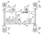
図1は、従来技術から知られている、ブレーキシステムの場合のメカトロニックシステム(いわゆる、ブレーキバイワイヤシステム:Brake-By-Wire-System)を示している。このブレーキシステムは、それぞれホイールブレーキ1a〜1dに割り当てられた、分割された複数の制御装置2a〜2dを含んでいる。ここで、ホイールブレーキ1は、所属の制御装置2と共に直接ホイール7a〜7dに配置されているメカトロニック的なブレーキコントローラー(電動モータ)として実現されている。
FIG. 1 shows a mechatronic system (so-called brake-by-wire-system) known from the prior art in the case of a brake system. The brake system includes a plurality of divided
フット・ブレーキペダル3を操作すると制動意思がペダルモジュール8によって処理され、データバス11a、11bを介して、個々の制御装置2へ伝達される。ペダルモジュール8は、ドライバーによって操作要素4を通じて駐車ブレーキに伝えられる、駐車ブレーキに対する要求をも処理する。
When the foot /
制御装置2は、バスシステム(バスケーブル)11a、11bを通じて互いに通信し合い、例えば個々の要素の作動可能性に関して、或いはブレーキ力の配分に関して、互いに情報を交換し合っている。制御装置は通常“フェール・サイレント”として作られており、従って制御装置は、エラーが発生していない間だけ作動し、エラー発生時には作動しないように構成されている。バスシステム11は、安全上の理由から冗長的に作られており、そのために二本のバスケーブル11a、11bが含まれている。
The
コックピットモジュール9(コックピット内の表示装置)は、これもまたバスシステム11に接続されており、ブレーキシステムの実際の状態を受取り、これに基づいて対応する情報或いは警告の指示をドライバーに示すことができる。ドライバーに対する信号の伝達は、例えば視覚的に或いは聴覚的に行うことができる。 The cockpit module 9 (display device in the cockpit), which is also connected to the bus system 11, receives the actual state of the brake system and can indicate corresponding information or warning instructions to the driver based on this. it can. Signal transmission to the driver can be performed, for example, visually or audibly.
バスシステム11には更に、ビークルダイナミクス制御のアルゴリズムが格納されている制御装置10が接続されている。その際そのアルゴリズムは基本的に、限界的走行状況を検知し、安定化の目的のために走行運転に介入することのできる、あらゆる任意のものとすることができる。既知の制御アルゴリズムには、例えばESP(電子的安定化プログラム:elektronisches Stabilitatsprogramm)、ABS(アンチロックシステム:Antriebsblockiersystem)、ASR(トラクション制御:Antriebsschlupfregelung)、VDM(ビークル・ダイナミクス・マネージメント:Vehicle Dynamics Management)、並びに、ロール安定化のための付加価値機能(例えば、ROM(転覆緩和:Roll Over Mitigation)、ARC(アクティブ・ロール制御:Active Roll Control)、或いは、例えばAFS(アクティブ・ステアリング:Active Front Steering)等の様なステアリング支援安定化システム等)がある。
The bus system 11 is further connected to a
図に示されている例では、フロントアクスルとリヤアクスルの制御装置2a、2c或いは2b、2dが、異なる電気回路12、13に接続され、別々の電源5、6から電気エネルギーの供給を受けている。ドライバーの制動要求を個々の制御装置2に伝達するペダルモジュール8は、安全上の理由から両方の部分電源回路網(電気回路)12、13に接続されており、冗長的に働く。
In the example shown in the figure, the front axle and rear
その様な分割された制御システムの重要な欠点は、必要となる冗長的設計の故に非常にコストが掛かり、複雑で、それ故高価であるという点にある。個々の制御装置2は、例えば冗長的な通信制御ユニットを必要とし、バスケーブル11a、11bは、異なる回路の上に冗長的に構成しなければならず、又例えばペダルモジュール8や制御装置10等のその他のシステム要素も冗長的に機能しなければならない。その上更に、制御装置2は、ホイール7の近くのホイールハウス内に配置されるので、強い負荷にさらされる。
An important drawback of such a split control system is that it is very costly, complicated and therefore expensive because of the required redundant design. Each
本発明の課題は、メカトロニクス式の車両システム、例えばブレーキシステム、ステアリングシステム、或いはシャーシシステムの形態である車両における走行挙動の制御装置を、より簡単に、コスト的により有利に、且つより確実に提供することである。
The object of the present invention is to provide a control device for driving behavior in a mechatronic vehicle system, for example a vehicle in the form of a brake system, a steering system or a chassis system, in a simpler, more advantageous and more reliable manner. It is to be.
本発明によれば、複数の制御要素と、該制御要素に接続された少なくとも一つの制御装置と、該制御装置に接続されたセンサとを備えた、ブレーキシステム、ステアリングシステム、或いはアクティブシャーシの形態である、車両における走行挙動の制御装置において、複数の制御要素に割り当てられた少なくとも一つの制御装置を備え、制御装置が構造的なユニットとして実現されている。 According to the invention, a brake system, a steering system, or an active chassis comprising a plurality of control elements, at least one control device connected to the control elements, and a sensor connected to the control device In the control device for driving behavior in a vehicle, at least one control device assigned to a plurality of control elements is provided, and the control device is realized as a structural unit.
本発明の重要な思想は、分割された複数の制御装置の機能を一つの制御装置に統合すること、それ故、複数の制御要素に割り当てられた一つの制御装置を用意し、この制御装置を構造的なユニットとして一つのハウジングに格納し、該ハウジングを、車両の、制御装置に加えられる機械的或いは熱的な負荷のより少ない場所に取付けるということにある。ここで“制御装置”というのは、特に、センサ信号を受取り、該信号を処理し、また制御信号を一つ又は複数の制御要素に対して送出す構造的ユニットであると理解されるものとする。“統合された”制御装置は、この目的のために好ましくは、様々な制御用に割当てられた、複数の制御モジュール(ハードウェア)を含んでいる。このことは、個々の制御モジュール間の通信を、従来の分割された制御装置間での通信よりも、遥かに簡単に行うことができるという非常に大きな利点を持っている。 An important idea of the present invention is that the functions of a plurality of divided control devices are integrated into one control device, and therefore one control device assigned to a plurality of control elements is prepared. It is housed in a single housing as a structural unit, which is mounted on a vehicle in a location with less mechanical or thermal load applied to the control device. As used herein, a “control device” is understood to be a structural unit that specifically receives sensor signals, processes the signals, and sends control signals to one or more control elements. To do. An “integrated” controller preferably includes a plurality of control modules (hardware) assigned for various purposes for this purpose. This has the great advantage that communication between individual control modules can be performed much more easily than communication between conventional divided control devices.
本発明の一つの好ましい実施例によれば、車両システムの全ての制御機能が唯一つの制御装置、即ち唯一つの構造的ユニット内にあり、その際この制御装置が車両システムの全ての(同じ働きを有する)制御要素に割り当てられている。これによって、個々の制御モジュール間の通信接続が、非常に簡単且つコスト的に有利に実現できるようになる。 According to one preferred embodiment of the invention, all control functions of the vehicle system are in a single control unit, i.e. a single structural unit, in which case this control unit performs all (the same function) of the vehicle system. Assigned) to the control element. As a result, communication connections between the individual control modules can be realized in a very simple and cost-effective manner.
制御装置の制御モジュールの間の通信接続は、好ましくはポイント間(ポイント・ツー・ポイント)接続(ピア・ツー・ピア[対等関係の接続環境])で実現される。即ち、データの伝達は、それぞれ正確に二つの制御モジュールの間だけで行われ、他の装置はその接続には接続されていない。これによって、データ伝達を特別に簡単に且つ確実に行うことができる。 The communication connection between the control modules of the control device is preferably realized in a point-to-point connection (peer-to-peer connection environment). That is, the transmission of data takes place between exactly two control modules, respectively, and no other device is connected to the connection. As a result, data transmission can be performed particularly simply and reliably.
制御装置の制御モジュールは、好ましくは機械的および/または熱的に遮断されている。発生する環境負荷から保護するために、個々のモジュールは、例えば鋳込まれるか或いはジェルを被せられることがある。熱的保護のためには、例えば、加熱された制御モジュールが他方の制御モジュールを同じ様に熱的に負荷することを防止するために、例えば温度バリヤーを組み込むことができる。 The control module of the control device is preferably mechanically and / or thermally disconnected. In order to protect against the environmental load that occurs, the individual modules may be cast or gelled, for example. For thermal protection, for example, a temperature barrier can be incorporated, for example, to prevent a heated control module from thermally loading the other control module in the same way.
制御装置は、好ましくは車両システムのセンサの近くに、例えばブレーキペダルセンサ、ステアリングホイールセンサの近くに配置される。それによって、センサは簡単、確実、且つコスト的に有利に“統合された”制御装置に接続されることが可能である。 The control device is preferably arranged in the vicinity of a sensor in the vehicle system, for example in the vicinity of a brake pedal sensor, a steering wheel sensor. Thereby, the sensor can be connected to an “integrated” control device in a simple, reliable and cost-effective manner.
制御装置中の制御モジュールは、好ましくは同一に作られている。これによって、システムの顕著な簡単化と著しいコスト削減が得られる。
制御装置の制御モジュールは、安全上の理由から、好ましくは少なくとも二つの異なる電源からエネルギーの供給を受ける。
The control modules in the control device are preferably made identical. This provides a significant simplification of the system and a significant cost reduction.
The control module of the control device is preferably supplied with energy from at least two different power sources for safety reasons.
この車両システムのもう一つの顕著な簡単化は、制御装置と接続されているセンサ(例えば、アクセルペダルセンサ)が、バスケーブルを通してではなく、従来の電線を通して制御装置と接続されている場合に得られる。 Another significant simplification of this vehicle system is obtained when the sensor connected to the control device (eg, accelerator pedal sensor) is connected to the control device through a conventional wire rather than through a bus cable. It is done.
本発明が以下に、添付の図面に基づいて例示として詳しく説明される。
図1の説明については明細書の導入部を参照されたい。
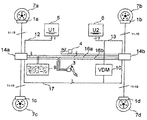
図2は、それぞれアクスル毎にブレーキコントローラー1a、1c或いは1b、1dに割り当てられている、“統合された”二つの制御装置14a、14bを備えたメカトロニクス式のブレーキシステムを示している。個々の制御装置14a或いは14bは、それぞれブレーキコントローラー1の中の二つのコントローラーのための制御機能を担っている。制御装置14a、14bは、ブレーキコントローラーから場所的に離されて、それぞれ閉じられたハウジング内に収容されている。
The invention will be described in detail hereinafter by way of example with reference to the accompanying drawings.
Please refer to the introductory part of the specification for the description of FIG.
FIG. 2 shows a mechatronic brake system with two “integrated”
制御装置14a、14bは、それぞれ従来からの電線16a、16bを通してフットブレーキペダルのセンサ3と接続されており、それ等の電線16a、16bは、安全上の理由から冗長的に作られている。ドライバーがフットブレーキ或いは駐車ブレーキの操作要素4に制動要求を伝えると、ブレーキシステムの制御要素1が、制御装置14a、14bにソフトウェアとして納められている、前もって定められた制動機能に従って制御される。制御装置14a、14b間の通信は、例えばCANのような、バス17を通して行われるが、このバス17には、ビークルダイナミクス制御の制御装置(VDM)10も接続されている。
The
二つの制御装置14a、14bは、異なる電源(U1又はU2)5又は6から電気エネルギーを供給されている。コックピットモジュール9もまた、バスケーブルを通じて制御装置14a、14bに接続されている。
The two
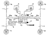
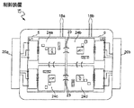
図3は、ブレーキコントローラー1のための全ての制御機能が単一の制御装置15に納められている、メカトロニクス式のブレーキシステムを示している。この制御装置15には、例えばビークルダイナミクス制御システム(例えばESP、VDM)、並びにその追加機能(例えば、ROM、ARC)の制御アルゴリズムも納められていることがある。
FIG. 3 shows a mechatronic brake system in which all control functions for the brake controller 1 are contained in a
制御装置15は、ここでは分離された二つの制御モジュール19a、19bを含んでおり、それ等のモジュールにはそれぞれ二つのブレーキコントローラー1、例えば1a、1c及び1b、1dが割り当てられている。制御装置15は直接ペダルセンサ装置に配置されており、これによって、とりわけ簡単且つコスト的に有利に制御装置15に対して接続することができる。
The
二つの制御モジュール19a及び19b間の通信は、ポイント・ツー・ポイント接続(ピア・ツー・ピア)を通じて行われ、この接続が、図1或いは図2で行われているような、バス接続11または17と置き換えられている。
Communication between the two
制御装置15は、二つの電源(U1、U2)5、6から冗長的に給電され且つコックピットモジュール9と接続されている。ブレーキコントローラー1に対する制御装置15の接続は、従来からの電線25a〜25dによって行われている。
The
唯一つの制御装置15しか備えていないこのブレーキシステムの構成は、通信の手間を最少化することを可能にする。センサ3と制御装置2との間のバスケーブル11と、図1及び図2に示されているような、制御装置14間のデータバス17が、ここでは簡単な電線25によって置き換えられている。
The configuration of this brake system with only one
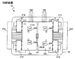
図4は、図3の制御装置15の一つの可能な実施態様を示している。この制御装置15は、機械的に分離された二つの制御モジュール19a、19bを含んでおり、それ等の制御モジュールは、それぞれ二つのブレーキコントローラー1に割り当てられている。各々の制御モジュール19a、19bは、接続端18a、18bを通して、ブレーキシステムのセンサ3、4に接続されており、またコネクター接続部20a、20bによって、対応するブレーキコントローラー1に接続することができる。
FIG. 4 shows one possible embodiment of the
制御モジュール19a、19bは、それぞれ、各々のブレーキコントローラー1のためのプロセッサユニット(μC1〜μC2)22a〜22dを含んでいる。制御装置15は更に、各々のブレーキコントローラー1(電動モータ)のためのそれぞれ一つの最終出力段階21a〜21dを含んでおり、それ等の最終出力段階は直接制御モジュール19に結合されている。
The
制御モジュール19a、19bは構造的に同型として構成されており、互いに180゜回転させて結合されている。二つのモジュール19a、19bの間の通信は、ポイント・ツー・ポイント接続23を通じて行われる。制御モジュール19aは一つの電源(U1)5から、また制御モジュール19bは別の電源(U2)6から給電される。制御装置15のハウジング内に含まれている構成グループは、互いに熱的に遮蔽され、又場合によっては鋳込まれるか或いはジェルを被せられることもある。代わりの手法として、制御装置15全体が保護されることもある。
The
図5は、図4の場合と同様の、制御装置15のもう一つの実施態様を示している。この実施例の場合には、制御装置を全体として更に堅牢にするために、各々のブレーキコントローラー1のために別々の(機械的に互いに分離された)制御モジュール24a〜24dを備えている。ここのモジュール24a〜24d間には、それぞれポイント・ツー・ポイント接続23がなされている。個々の制御モジュール24は、ここでも又構造的に同型として構成され、回転させて配置されている。制御装置15の構造のその他の部分は、図4のそれに対応している。
FIG. 5 shows another embodiment of the
先にメカトロニクス式のブレーキシステムの例について述べられたのと同じことが、例えばアクティブステアリングシステム或いはアクティブシャーシ等の他の車両システムについても同様に当てはまる。その場合には、システムの制御要素1が、例えばステアリングコントローラー或いはアクティブスプリング要素/ダンパー要素となるであろう。しかしながら制御装置15の個々の要素の配置及び配線がそれによって変化することはない。
The same as described above for the example of a mechatronic brake system applies equally to other vehicle systems, such as an active steering system or an active chassis. In that case, the control element 1 of the system would be, for example, a steering controller or an active spring element / damper element. However, the arrangement and wiring of the individual elements of the
1…ブレーキコントローラー
2…制御装置
3…フットブレーキペダルのセンサ
4…駐車ブレーキの操作要素
5…第一の電源
6…第二の電源
7…ホイール
8…ペダルモジュール
9…コックピットモジュール
10…制御装置
11…バスケーブル
12…第一の部分電源回路網(電気回路)
13…第二の部分電源回路網(電気回路)
14…制御装置
15…制御装置
16…電線
17…バス接続
18…センサ入力端
19…制御モジュール
20…コネクター
21…エンジン最終段
22…プロセッサユニット
23…ポイント・ツー・ポイント(ポイント間)接続
24…制御モジュール
25…制御電線
DESCRIPTION OF SYMBOLS 1 ...
13 ... Second partial power supply network (electric circuit)
DESCRIPTION OF SYMBOLS 14 ...
Claims (10)
複数の制御要素(1)に割り当てられた少なくとも一つの制御装置(14、15)を備え、制御装置(14、15)が構造的なユニットとして実現されていること、
を特徴とする車両における走行挙動の制御装置。 Brake system comprising a plurality of control elements (1), at least one control device (2) connected to the control element (1), and a sensor (3) connected to the control device (2) In the control device for the driving behavior in the vehicle which is in the form of a steering system or an active chassis,
Comprising at least one control device (14, 15) assigned to a plurality of control elements (1), the control device (14, 15) being realized as a structural unit;
An apparatus for controlling a running behavior in a vehicle characterized by the above.
Applications Claiming Priority (1)
| Application Number | Priority Date | Filing Date | Title |
|---|---|---|---|
| DE200410017386 DE102004017386A1 (en) | 2004-04-08 | 2004-04-08 | Vehicle system with combined control units |
Publications (1)
| Publication Number | Publication Date |
|---|---|
| JP2005297953A true JP2005297953A (en) | 2005-10-27 |
Family
ID=34895527
Family Applications (1)
| Application Number | Title | Priority Date | Filing Date |
|---|---|---|---|
| JP2005098022A Withdrawn JP2005297953A (en) | 2004-04-08 | 2005-03-30 | Control device for running behavior in vehicle |
Country Status (3)
| Country | Link |
|---|---|
| EP (1) | EP1584532A1 (en) |
| JP (1) | JP2005297953A (en) |
| DE (1) | DE102004017386A1 (en) |
Families Citing this family (5)
| Publication number | Priority date | Publication date | Assignee | Title |
|---|---|---|---|---|
| DE102004039998B4 (en) | 2004-08-18 | 2014-03-27 | Knorr-Bremse Systeme für Nutzfahrzeuge GmbH | Commercial vehicle with multiple, controlled by at least one electronic control unit electrical equipment |
| US8682559B2 (en) | 2010-12-14 | 2014-03-25 | Nxp B.V. | Distributed electrical brake circuit and system |
| FR3023814B1 (en) * | 2014-07-16 | 2017-12-08 | Chassis Brakes Int Bv | BRAKE CONTROL DEVICE FOR VEHICLE |
| DE102017212708A1 (en) * | 2017-07-25 | 2019-01-31 | Robert Bosch Gmbh | Controller-actuator assembly |
| DE102021119939A1 (en) * | 2021-07-30 | 2023-02-02 | Knorr-Bremse Systeme für Nutzfahrzeuge GmbH | Redundant electromechanical braking system and actuator therefor |
Family Cites Families (7)
| Publication number | Priority date | Publication date | Assignee | Title |
|---|---|---|---|---|
| DE19832167A1 (en) * | 1997-11-22 | 1999-05-27 | Itt Mfg Enterprises Inc | Electromechanical braking system for cars |
| US6185497B1 (en) * | 1998-03-20 | 2001-02-06 | Denso Corporation | Apparatus for controlling behavior of vehicle using brakes |
| US6122568A (en) * | 1998-12-22 | 2000-09-19 | Ford Global Technologies, Inc. | Method and apparatus for determining the dynamic stability of an automotive vehicle |
| DE10044319A1 (en) * | 2000-09-07 | 2002-03-21 | Bosch Gmbh Robert | Electronic system for a vehicle and system layer for operational functions |
| DE10112514A1 (en) * | 2000-12-22 | 2002-06-27 | Volkswagen Ag | X-by-wire system for vehicle has redundant modules in units with first modules networked to form subsystem, likewise second modules; second subsystem consists only of second modules |
| DE10065118A1 (en) * | 2000-12-28 | 2002-07-04 | Bosch Gmbh Robert | System and method for controlling and / or monitoring a control device network having at least two control devices |
| DE10135020B4 (en) * | 2001-07-18 | 2005-03-03 | Robert Bosch Gmbh | Method and device for detecting and eliminating a risk of tipping over |
-
2004
- 2004-04-08 DE DE200410017386 patent/DE102004017386A1/en not_active Withdrawn
-
2005
- 2005-03-11 EP EP05101920A patent/EP1584532A1/en not_active Withdrawn
- 2005-03-30 JP JP2005098022A patent/JP2005297953A/en not_active Withdrawn
Also Published As
| Publication number | Publication date |
|---|---|
| EP1584532A1 (en) | 2005-10-12 |
| DE102004017386A1 (en) | 2005-10-27 |
Similar Documents
| Publication | Publication Date | Title |
|---|---|---|
| US7433771B2 (en) | Utility vehicle having a plurality of electric devices which are controlled by at least one electronic control device | |
| JP5254334B2 (en) | Brake device for vehicle and method for operating vehicle brake device | |
| US6390565B2 (en) | Brake by wire system with separate controllers and both position and force input sensors | |
| US6522962B2 (en) | Distributed control architecture for mechatronic automotive systems | |
| CN106132793A (en) | With compressed air run brakes controller, there is the brakes of this controller and there is the vehicle of this brakes | |
| US7293842B2 (en) | Control network for vehicle dynamics and ride control systems having distributed electronic control units | |
| EP3523148A2 (en) | Trailer power and communication management | |
| CN110536817B (en) | Vehicle brake system | |
| JPWO2018181807A1 (en) | Vehicle brake system | |
| JPH11263212A (en) | Brake system for vehicle | |
| EP2085276A1 (en) | Distributed electrical/electronic architectures for brake-by-wire brake systems | |
| US6959968B2 (en) | Central electronic control network for vehicle dynamics and ride control systems in heavy vehicles | |
| KR101349467B1 (en) | Failsafe Method for Steer By Wire Vehicle | |
| JP2005297953A (en) | Control device for running behavior in vehicle | |
| EP3604055A1 (en) | Vehicular brake system | |
| WO2023013337A1 (en) | Vehicle system | |
| KR101870634B1 (en) | Integrated electronic control unit | |
| CN114701472A (en) | Electric control brake system | |
| JP2001525289A (en) | Coupling system for controlling the driving state of a car | |
| JP2008522884A (en) | Distributing antilock brake system | |
| CN114599560B (en) | Electric brake system for vehicle | |
| CN112714727A (en) | Brake system for vehicle | |
| JP7392400B2 (en) | motor control system | |
| KR19980078162A (en) | Automotive Chassis Integrated Electronic Control Unit | |
| JP2018172031A (en) | Vehicle brake system |
Legal Events
| Date | Code | Title | Description |
|---|---|---|---|
| A300 | Withdrawal of application because of no request for examination |
Free format text: JAPANESE INTERMEDIATE CODE: A300 Effective date: 20080603 |