JP2005297877A - Vehicle steering device - Google Patents
Vehicle steering device Download PDFInfo
- Publication number
- JP2005297877A JP2005297877A JP2004119762A JP2004119762A JP2005297877A JP 2005297877 A JP2005297877 A JP 2005297877A JP 2004119762 A JP2004119762 A JP 2004119762A JP 2004119762 A JP2004119762 A JP 2004119762A JP 2005297877 A JP2005297877 A JP 2005297877A
- Authority
- JP
- Japan
- Prior art keywords
- electric motors
- steering
- turning
- electric motor
- rotation
- Prior art date
- Legal status (The legal status is an assumption and is not a legal conclusion. Google has not performed a legal analysis and makes no representation as to the accuracy of the status listed.)
- Granted
Links
Images


Landscapes
- Steering Control In Accordance With Driving Conditions (AREA)
- Power Steering Mechanism (AREA)
Abstract
【課題】 転舵輪を転舵するための少なくとも2つの電動モータを備えたステアバイワイヤ方式の車両の操舵装置において、的確に電動モータの状態を検出する。
【解決手段】 イグニッションスイッチの投入直後に、第1および第2転舵用ECU36,37は、第1および第2転舵用電動モータ24,25の正常状態における各駆動力が互い均衡かつ対抗するように第1および第2転舵用電動モータ24,25に駆動電流を流す。そして、第1および第2転舵用電動モータ24,25が回転しないとき、第1および第2転舵用電動モータ24,25の正常を判定する。正常が判定されないとき、第1および第2転舵用電動モータ24,25の一方の駆動電流を徐々に増加させることにより、第1および第2転舵用電動モータ24,25の回転が停止した時点で、第1または第2転舵用電動モータ24,25の劣化などによる効率低下を判定する。
【選択図】 図1PROBLEM TO BE SOLVED: To accurately detect a state of an electric motor in a steer-by-wire type vehicle steering apparatus provided with at least two electric motors for turning steered wheels.
Immediately after the ignition switch is turned on, the first and second turning ECUs 36 and 37 have the driving forces in the normal state of the first and second turning electric motors 24 and 25 balanced and opposed to each other. In this way, a drive current is passed through the first and second steering electric motors 24 and 25. When the first and second steered electric motors 24 and 25 do not rotate, the normality of the first and second steered electric motors 24 and 25 is determined. When normality is not determined, rotation of the first and second steering electric motors 24 and 25 is stopped by gradually increasing the drive current of one of the first and second steering electric motors 24 and 25. At this time, it is determined whether the efficiency is reduced due to deterioration of the first or second electric motor 24 or 25 for turning.
[Selection] Figure 1
Description
本発明は、転舵輪を転舵するための少なくとも2つの電動モータまたは操舵ハンドルに操舵反力を付与するための少なくとも2つの電動モータを備えたステアバイワイヤ方式の車両の操舵装置に関する。 The present invention relates to a steer-by-wire vehicle steering apparatus including at least two electric motors for turning steered wheels or at least two electric motors for applying a steering reaction force to a steering handle.
従来から、主操舵アクチュエータおよび副操舵アクチュエータとしての2つの電動モータを備え、両方の電動モータが共に正常であるときには両方の電動モータの回転によって転舵輪を転舵し、一方の電動モータの異常時には他方の電動モータのみの回転によって転舵輪を転舵するステアバイワイヤ方式の車両の操舵装置は知られている(下記特許文献1参照)。
しかし、上記特許文献1においては、電動モータの異常を検出する方法については、何ら説明されていない。 However, the above Patent Document 1 does not describe any method for detecting an abnormality of the electric motor.
本発明の目的は、転舵輪を転舵するための少なくとも2つの電動モータまたは操舵ハンドルに操舵反力を付与するための少なくとも2つの電動モータを備えたステアバイワイヤ方式の車両の操舵装置において、的確に電動モータの状態を検出できるようにすることにある。 SUMMARY OF THE INVENTION An object of the present invention is to provide a steer-by-wire vehicle steering apparatus having at least two electric motors for turning steered wheels or at least two electric motors for applying a steering reaction force to a steering handle. In other words, the state of the electric motor can be detected.
上記目的を達成するために、本発明の特徴は、転舵輪を転舵するための少なくとも2つの電動モータまたは操舵ハンドルに操舵反力を付与するための少なくとも2つの電動モータを備えたステアバイワイヤ方式の車両の操舵装置において、2つの電動モータによる各駆動力が互いに対抗するように同2つの電動モータに駆動電流を流して、同2つの電動モータの回転および非回転により同2つの電動モータの状態を判定する判定手段を設けたことにある。この場合、2つの電動モータに駆動電流を流すタイミングは、例えば、イグニッションスイッチを投入した直後である。 In order to achieve the above object, a feature of the present invention is a steer-by-wire system including at least two electric motors for turning steered wheels or at least two electric motors for applying a steering reaction force to a steering handle. In the vehicle steering apparatus, a drive current is supplied to the two electric motors so that the driving forces of the two electric motors oppose each other, and the two electric motors rotate and non-rotate. The determination means for determining the state is provided. In this case, the timing when the drive current is supplied to the two electric motors is, for example, immediately after the ignition switch is turned on.
電動モータの発生駆動力は、電動モータの特性により、駆動電流の大きさに依存する。したがって、前記本発明のように、2つの電動モータの各駆動力が互いに対抗するように同2つの電動モータに駆動電流を流せば、一方の電動モータは他方の電動モータを互いに回転させようとする。そして、この状態で、2つの電動モータの回転および非回転を観察すれば、2つの電動モータの一方に異常が発生して駆動力を発生しなかったり、一方の電動モータの効率が低下していることなど、すなわち電動モータの状態を簡単に判定できるようになる。 The generated driving force of the electric motor depends on the magnitude of the driving current depending on the characteristics of the electric motor. Therefore, as in the present invention, if a driving current is passed through the two electric motors so that the driving forces of the two electric motors oppose each other, one electric motor tries to rotate the other electric motor relative to each other. To do. In this state, if the rotation and non-rotation of the two electric motors are observed, an abnormality occurs in one of the two electric motors and no driving force is generated, or the efficiency of the one electric motor decreases. That is, it is possible to easily determine the state of the electric motor.
より具体的には、前記判定手段を、例えば、2つの電動モータの回転を検出する回転検出手段と、2つの電動モータの正常状態における各駆動力が互いに均衡しかつ対抗するように同2つの電動モータの特性に従って予め定められた所定の駆動電流を同2つの電動モータにそれぞれ流した状態で、前記回転検出手段によって前記2つの電動モータの回転が検出されないとき、同2つの電動モータの正常を判定する第1判定手段とで構成するとよい。 More specifically, the determination means includes, for example, a rotation detection means for detecting the rotation of two electric motors, and the same two so that the driving forces in a normal state of the two electric motors are balanced and opposed to each other. When rotations of the two electric motors are not detected by the rotation detection means in a state where a predetermined drive current predetermined according to the characteristics of the electric motors is supplied to the two electric motors, the normality of the two electric motors is normal. It is good to comprise with the 1st determination means which determines.
2つの電動モータに異常が発生していたり、同2つの電動モータが劣化したりしていなければ、2つの電動モータによりそれぞれ発生される駆動力は均衡するので、2つの電動モータは回転しない。したがって、第1判定手段により、2つの電動モータの正常が簡単に判定される。また、この2つの電動モータの正常の判定時には、転舵輪が転舵され、または操舵ハンドルが回転されることはないので、運転者が違和感をもつこともない。 If there is no abnormality in the two electric motors or the two electric motors are not deteriorated, the driving forces generated by the two electric motors are balanced, so the two electric motors do not rotate. Therefore, the normality of the two electric motors is easily determined by the first determination means. In addition, when the two electric motors are judged to be normal, the steered wheels are not steered or the steering handle is not rotated, so that the driver does not feel uncomfortable.
また、前記判定手段が、さらに、第1判定手段によって2つの電動モータの正常が判定されないとき、同2つの電動モータに流れる電流に差が生じるように少なくとも一方の電動モータへの駆動電流の大きさを変更して、回転検出手段による2つの電動モータの回転の検出に基づいて同2つの電動モータの状態を判定する第2判定手段を含むように構成できる。この場合、第2判定手段は、2つの電動モータに流れる電流の差が徐々に大きくなるように少なくとも一方の電動モータへの駆動電流の大きさを変更するようにするとよい。また、第2判定手段は、回転検出手段によって2つの電動モータの回転が検出されないとき、同2つの電動モータに流れる電流の差に応じて一方の電動モータの低下効率を決定する機能を含むようにするとよい。 Further, when the determination unit further determines that the normality of the two electric motors is not determined by the first determination unit, the magnitude of the drive current to at least one of the electric motors is different so that a difference occurs in the current flowing through the two electric motors. It can be configured to include a second determination unit that determines the state of the two electric motors based on detection of rotation of the two electric motors by the rotation detection unit. In this case, the second determination unit may change the magnitude of the drive current to at least one of the electric motors so that the difference between the currents flowing through the two electric motors gradually increases. Further, the second determination means includes a function of determining a reduction efficiency of one of the electric motors according to a difference between currents flowing through the two electric motors when rotation of the two electric motors is not detected by the rotation detection means. It is good to make it.
2つの電動モータのうちの一方の電動モータが、作動不能になったわけではなく、単に劣化して十分な駆動力を発生することができない場合には、この一方の電動モータの駆動電流を他方の電動モータに対する駆動電流よりも大きくすれば、2つの電動モータの駆動力が互いに釣り合って2つの電動モータの回転が停止する。したがって、第2判定手段により、一方の電動モータの効率低下も簡単に判定できる。 If one of the two electric motors has not become inoperable, but simply deteriorates and cannot generate sufficient driving force, the drive current of the one electric motor is reduced to the other. If it is larger than the driving current for the electric motor, the driving forces of the two electric motors balance each other and the rotation of the two electric motors stops. Therefore, the second determination means can also easily determine a decrease in the efficiency of one of the electric motors.
以下、本発明の一実施形態に係る車両の操舵装置について図面を用いて説明する。図1は、同実施形態に係る車両の操舵装置を概略的に示している。 A vehicle steering apparatus according to an embodiment of the present invention will be described below with reference to the drawings. FIG. 1 schematically shows a steering apparatus for a vehicle according to the embodiment.
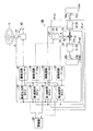
この車両の操舵装置は、運転者によって操作される操舵操作装置10と、左右前輪FW1,FW2を前記運転者の操作により転舵する転舵装置20とを機械的に分離したステアバイワイヤ方式を採用している。操舵操作装置10は、運転者によって回転操作される操作部としての操舵ハンドル11を備えている。操舵ハンドル11は操舵入力軸12の上端に固定され、操舵入力軸12はその下端にて減速機構を内蔵した反力発生用の操舵反力用電動モータ13により回転駆動されるようになっている。
This vehicle steering device employs a steer-by-wire system in which a
また、転舵装置20は、車両の左右方向に延びて配置された転舵軸21を備えている。この転舵軸21の両端部には、タイロッド22a,22bおよびナックルアーム23a,23bを介して、転舵輪としての左右前輪FW1,FW2が転舵可能に接続されている。左右前輪FW1,FW2は、転舵軸21の軸線方向の変位により左右に転舵される。転舵軸21の外周上には、図示しないハウジングに組み付けられた第1転舵用電動モータ24および第2転舵用電動モータ25が設けられている。第1転舵用電動モータ24および第2転舵用電動モータ25の回転は、それぞれねじ送り機構26,27により減速されるとともに転舵軸21の軸線方向の変位に変換される。なお、第1および第2転舵用電動モータ24,25の特性、すなわち駆動電流の大きさに対する発生駆動力の大きさの特性は同じであっても異なっていてもよい。
The
次に、操舵反力用電動モータ13、第1転舵用電動モータ24および第2転舵用電動モータ24,25の回転を制御する電気制御装置30について説明する。電気制御装置30は、操舵角センサ31、転舵角センサ32、第1および第2回転角センサ33,34を備えている。操舵角センサ31は、操舵入力軸12に組み付けられて、操舵ハンドル11の中立位置からの回転角を検出して操舵角θとして出力する。転舵角センサ32は、転舵軸21の外周上にて図示しないハウジングに組み付けられ、転舵軸21の基準位置からの軸線方向の変位量を検出して転舵角δとして出力する。なお、これらの操舵角θおよび転舵角δは、中立位置を「0」とし、右方向の角度を正の値で、左方向の角度を負の値でそれぞれ表す。第1および第2回転角センサ33,34は、第1および第2電動モータ24,25にそれぞれ組み付けられ、第1および第2電動モータ24,25の基準位置からの第1および第2回転角θm1,θm2をそれぞれ検出する。なお、これらの第1および第2回転角θm1,θm2も、正負の符号により基準位置からの回転方向を表す。
Next, the
また、電気制御装置30は、操舵角センサ31に接続された操舵反力用電子制御ユニット(以下、操舵反力用ECUという)35と、操舵角センサ31、転舵角センサ32および第1回転角センサ33に接続された第1転舵用電子制御ユニット(以下、第1転舵用ECUという)36と、操舵角センサ31、転舵角センサ32および第2回転角センサ34に接続された第2転舵用電子制御ユニット(以下、第2転舵用ECUという)37とを備えている。これらのECU35〜37は、それぞれCPU,ROM,RAMなどからなるマイクロコンピュータを主要構成部品とする。そして、これらの3つのECU35は互いに接続されて、各種動作を連絡し合う。
Further, the
操舵反力用ECU35は、ROMに記憶した図2の操舵反力制御プログラムを所定の短時間ごとに繰り返し実行して、駆動回路41を介して操舵用電動モータ13を駆動制御する。第1転舵用ECU36は、ROMに記憶した図3の第1チェックプログラムをイグニッションスイッチの投入直後に1回だけ実行して、第1転舵用電動モータ24の状態を判定する。また、第1転舵用ECU36は、その後、ROMに記憶した図5の転舵制御プログラムを所定の短時間ごとに繰り返し実行して、駆動回路42を介して第1転舵用電動モータ24を駆動制御する。第2転舵用ECU37は、ROMに記憶した図4の第2チェックプログラムをイグニッションスイッチの投入直後に1回だけ実行して、第2転舵用電動モータ25の状態を判定する。また、第2転舵用ECU37は、その後、ROMに記憶した図5の転舵制御プログラムを所定の短時間ごとに繰り返し実行して、駆動回路43を介して第2転舵用電動モータ25を駆動制御する。なお、3つのECU35〜37を設けるのに代えて、1つまたは2つのECUによって前記各制御を適宜行うようにしてもよい。
The steering reaction force ECU 35 repeatedly executes the steering reaction force control program of FIG. 2 stored in the ROM every predetermined short time, and drives and controls the steering
駆動回路41〜43は、ECU35〜37により制御されて、電動モータ13,24,25を駆動制御する。これらの駆動回路41〜43内には、電動モータ13,24,25に流れる駆動電流をそれぞれ検出する駆動電流センサ41a〜43aがそれぞれ設けられていて、駆動電流センサ41a〜43aによって検出された駆動電流はECU35〜37にそれぞれ供給される。また、ECU36,37には、電動モータ24の異常を運転者に警告するための警報ランプ、警報ブザーなどの警報器44が接続されている。
The
次に、上記のように構成した実施形態の動作を説明する。イグニッションスイッチ(図示しない)の投入直後、第1および第2転舵用ECU36,37は、図3の第1チェックプログラムおよび図4の第2チェックプログラムの実行をそれぞれ1回だけ行う。
Next, the operation of the embodiment configured as described above will be described. Immediately after the ignition switch (not shown) is turned on, the first and
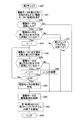
第1チェックプログラムの実行は、ステップS20にて開始され、第1転舵用ECU36は、ステップS21にて、駆動電流センサ42aによって検出された駆動電流を入力するとともに、同入力した駆動電流を用いて駆動回路42を制御し、第1転舵用電動モータ24を第1方向に回転させるように同電動モータ24に駆動電流I1を流す。第2チェックプログラムの実行は、ステップS40にて開始され、第2転舵用ECU37は、ステップS41にて、駆動電流センサ43aによって検出された駆動電流を入力するとともに、同入力した駆動電流を用いて駆動回路43を制御し、第2転舵用電動モータ25を第2方向に回転させるように同電動モータ25に駆動電流I2を流す。
The execution of the first check program is started in step S20, and the
この場合、前記第1および第2方向は、互いに反対の回転方向、すなわち転舵軸21を互いに反対方向に駆動するための回転方向である。また、駆動電流I1,I2は、共に正常状態にある第1および第2転舵用電動モータ24,25の各発生駆動力が互いに均衡するように、第1および第2転舵用電動モータ24,25の駆動電流に対する発生駆動力の各特性に従って予め定められた大きさの電流である。すなわち、第1および第2転舵用電動モータ24,25の駆動電流に対する発生駆動力の各特性が等しければ(例えば、第1および第2転舵用電動モータ24,25が同一の電動モータでそれぞれ構成されていれば)、駆動電流I1,I2は互いに等しい。第1および第2転舵用電動モータ24,25の駆動電流に対する発生駆動力の各特性が異なれば、駆動電流I1,I2は互いに異なる。
In this case, the first and second directions are rotation directions opposite to each other, that is, rotation directions for driving the steered
前記ステップS21の処理後、第1転舵用ECU36は、ステップS22にて回転角センサ33によって検出された第1回転角θm1を入力して、第1転舵用電動モータ24が回転したか否かを判定する。一方、前記ステップS41の処理後、第2転舵用ECU37は、ステップS42にて回転角センサ34によって検出された第2回転角θm2を入力して、第2転舵用電動モータ25が回転したか否かを判定する。
After the process of step S21, the
いま、第1および第2転舵用電動モータ24,25が正常であれば、第1および第2転舵用電動モータ24,25は、互いに均衡した駆動力で、他方の電動モータ25,24をそれぞれ回転させようとするので、第1および第2転舵用電動モータ24,25は共に回転しない。なお、第1および第2転舵用電動モータ24,25によって発生される駆動力が極めて正確に一致しなくても、同駆動力がほぼ一致すれば、各部品間の摩擦損失によって第1および第2転舵用電動モータ24,25は回転しない。したがって、この場合には、第1転舵用ECU36は、ステップS22にて「No」と判定し、ステップS32にて第1転舵用電動モータ24に対する駆動電流の供給を停止制御することにより第1転舵用電動モータ24の駆動制御を解除する。そして、ステップS33にて第2転舵用ECU37に第1チェックプログラムの終了を通知して、ステップS34にてこの第1チェックプログラムの実行を終了する。一方、第2転舵用ECU37は、ステップS42にて「No」と判定し、ステップS52にて第2転舵用電動モータ25に対する駆動電流の供給を停止制御することにより第2転舵用電動モータ25の駆動制御を解除する。そして、ステップS53にて第1転舵用ECU36に第2チェックプログラムの終了を通知して、ステップS54にてこの第1チェックプログラムの実行を終了する。
If the first and second steered
これらの第1および第2チェックプログラムの終了後、第1および第2転舵用ECU36,37は、図5の転舵制御プログラムの実行を所定の短時間ごとに繰り返し実行し始める。これらの転舵制御プログラムの実行はそれぞれステップS60にて開始され、第1および第2転舵用ECU36,37は、ステップS61にて、操舵角センサ31によって検出された操舵角θをそれぞれ入力するとともに、転舵角センサ32によって検出された転舵角δを入力する。
After the completion of the first and second check programs, the first and
次に、第1および第2転舵用ECU36,37は、ステップS62にて、各ROM内に予め用意された目標転舵角テーブルを参照して、前記入力した操舵角θに対応する目標転舵角δ*を計算する。この目標転舵角テーブルは、図6に示すように、操舵角θの絶対値|θ|の増加に従って絶対値の増加する目標転舵角δ*を記憶している。なお、目標転舵角テーブルを用いるのに代えて、操舵角θと目標転舵角δ*との関係を予め定めた関数を用意しておいて、同関数を用いて前記入力した操舵角θに対応する目標転舵角δ*を計算するようにしてもよい。また、車速センサ、ヨーレートセンサ、横加速度センサなどを設けて、前記各センサによって検出された車速、ヨーレート、横加速度などに応じて前記計算した目標転舵角δ*を補正するようにしてもよい。
Next, in step S62, the first and
前記目標転舵角δ*の計算後、第1および第2転舵用ECU36,37は、ステップS63にて第1および第2転舵用電動モータ24,25を駆動制御して、ステップS64にてこの転舵制御プログラムの実行を一旦終了する。このステップS63の処理においては、前記計算した目標転舵角δ*と前記入力した転舵角δとの差δ*−δが計算され、駆動回路42,43との協働により、第1および第2転舵用電動モータ24,25は前記差δ*−δが「0」となるように駆動制御される。これにより、第1および第2転舵用電動モータ24,25は、それらの回転により、ねじ送り機構26,27を介して転舵軸21を軸線方向に駆動する。そして、転舵軸21の軸線方向の変位により、左右前輪FW1,FW2が目標転舵角δ*に転舵される。その結果、左右前輪FW1,FW2は、操舵ハンドル11の回動操作に応じて転舵され、車両は左右に旋回される。
After the calculation of the target turning angle δ *, the first and second turning
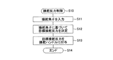
このような転舵制御プログラムの実行と並行して、操舵反力用ECU35は、図2の操舵反力制御プログラムを所定の短時間ごとに繰り返し実行している。この操舵反力プログラムの実行はステップS10にて開始され、操舵反力用ECU35は、ステップS11にて操舵角センサ31によって検出された操舵角θを入力する。
In parallel with the execution of the steering control program, the steering
次に、操舵反力用ECU35は、目標操舵反力テーブルを参照して、前記入力した操舵角θに対応する目標操舵反力を計算する。この目標操舵反力テーブルは、図7に示すように、操舵角θの絶対値|θ|の増加に従って絶対値の増加する目標操舵反力を記憶している。なお、目標操舵反力テーブルを用いるのに代えて、操舵角θと目標操舵反力との関係を予め定めた関数を用意しておいて、同関数を用いて前記入力した操舵角θに対応する目標操舵反力を計算するようにしてもよい。なお、この場合にも、車速、ヨーレート、横加速度などに応じて目標操舵反力を補正してもよい。
Next, the steering
前記目標操舵反力の計算後、ステップS13にて、駆動電流センサ41aによって検出された駆動電流を用いて、操舵ハンドル11に付与される反力トルクが前記計算した目標操舵反力に一致するように駆動回路41を介して操舵反力用電動モータ13の回転を制御する。そして、ステップS14にて、この転舵制御プログラムの実行を一旦終了する。これにより、運転者による操舵ハンドル11の回動操作に対して、操舵ハンドル11の操舵角θすなわち左右前輪FW1,FW2の転舵角δに応じた反力トルクが付与される。したがって、運転者は、この操舵反力を感じながら、操舵ハンドル11を回動操作できる。
After the calculation of the target steering reaction force, the reaction force torque applied to the steering handle 11 is matched with the calculated target steering reaction force using the drive current detected by the drive current sensor 41a in step S13. In addition, the rotation of the steering reaction force
次に、第1および第2転舵用電動モータ24,25のいずれか一方が正常でない場合について説明する。この場合、前述の場合と異なり、第1および第2転舵用電動モータ24,25のうちの一方が他方を回転させることになるので、第1および第2転舵用電動モータ24,25は共に回転する。したがって、図3のステップS22にて「Yes」と判定され、第1転舵用ECU36はステップS23に進み、第1転舵用電動モータ24が第1方向と反対方向(すなわち、第2方向)に回転しているかを判定する。この第1方向と反対方向の第1転舵用電動モータ24の回転は、第1転舵用電動モータ24が第2転舵用電動モータ25によって回転させられたことを意味する。一方、第2転舵用ECU37はステップS42にて「Yes」と判定し、ステップS43にて第2転舵用電動モータ25が第2方向と反対方向(すなわち、第1方向)に回転しているかを判定する。この第2方向と反対方向の第2転舵用電動モータ25の回転は、第2転舵用電動モータ25が第1転舵用電動モータ24によって回転させられたことを意味する。
Next, a case where one of the first and second steering
第1転舵用電動モータ24が第1方向と反対方向に回転したとすると、第1転舵用ECU36は、ステップS23にて「Yes」と判定し、ステップS24以降の処理を実行する。一方、この場合、第2転舵用電動モータ25も第1方向と反対方向すなわち第2方向に回転するので、第2転舵用ECU37は、ステップS43にて「No」と判定して、ステップS51にて第1転舵用ECU36からの第1チェックプログラムの終了の通知を待つ。この間、第2転舵用電動モータ25には前記ステップS41の処理によって流された駆動電流I2が流され続ける。
If the first steered
第1転舵用ECU36は、ステップS24にて変数nを「1」に初期設定した後、ステップS27の変数nのカウントアップ処理およびステップS28の変数nの比較処理により、変数nが所定値N以上になるまで、ステップS25〜S28からなる循環処理を繰り返し実行する。なお、この所定値Nは予め決められた自然数であって、この値が大きくなるほど、ステップS25〜S28からなる循環処理回数が大きくなり得る。この循環修理中、ステップS25の処理により、第1転舵用電動モータ24に流す駆動電流を微小電流ΔIずつ増加させる。ステップS26の処理により、前記駆動電流を増加させた状態で、回転角センサ33からの検出第1回転角θm1を入力して、第1転舵用電動モータ24が第1方向と反対方向に回転しているかを検出する。言い換えれば、第1転舵用電動モータ24が、前記駆動電流の増加によって停止したかを判定する。
After first setting the variable n to “1” in step S24, the
第1転舵用電動モータ24が第1方向と反対方向に回転し続けていると、前記ステップS25の駆動電流の増加処理がふたたび実行され、その後、前記ステップS26の判定処理が実行される。このようなステップS25〜S28からなる循環処理中、第1転舵用電動モータ24が第1方向と反対方向に回転しなくなると、ステップS26にて「No」と判定して、ステップS29に進む。この状態は、第1転舵用電動モータ24に流す駆動電流を第2転舵用電動モータ25に流す駆動電流よりも増加電流n・ΔIだけ大きくしたときに、第1および第2転舵用電動モータ24,25の駆動力が釣り合ったことを意味する。言い換えれば、第1転舵用電動モータ24の効率が、同電動モータ24の劣化などにより、増加電流n・ΔI分だけ低下したことを意味する。ステップS29においては、第1転舵用電動モータ24の効率が低下していることを記憶するとともに、第1転舵用電動モータ24に対する増加電流n・ΔIを記憶する。なお、この第1転舵用電動モータ24の効率低下を運転者に知らせるようにしてもよい。
If the first steered
一方、変数nが所定値N以上になっても、第1転舵用電動モータ24が第1方向と反対方向に回転し続けている場合には、ステップS28にて「Yes」と判定して、ステップS30に進む。この状態は、第1転舵用電動モータ24に流す駆動電流を第2転舵用電動モータ25に流す駆動電流よりも(N−1)・ΔI(ある程度大きな電流)だけ大きくしても、第1および第2転舵用電動モータ24,25の駆動力が釣り合わなかったことを意味する。言い換えれば、第1転舵用電動モータ24が作動不能に陥っていることを意味する。ステップS30においては、警報器44を作動させて、第1転舵用電動モータ24に異常が発生していることを運転者に通報する。
On the other hand, if the first steering
前記ステップS29またはステップS30の処理後、第1転舵用ECU36はステップS32にて第1転舵用電動モータ24の駆動制御を解除し、ステップS33にて第2転舵用ECU37に第1チェックプログラムの終了を通知して、ステップS34にてこの第1チェックプログラムの実行を終了する。
After the process of step S29 or step S30, the
この第1チェックプログラムの終了の通知により、第2転舵用ECU37は、図4のステップS51にて「Yes」と判定して、ステップS52の第2転舵用電動モータ25の駆動制御の解除処理およびステップS53の第1転舵用ECU36に対する通知処理を実行した後、ステップS54にてこの第2チェックプログラムの実行を終了する。
Upon notification of the end of the first check program, the
次に、第1転舵用電動モータ24が第1方向に回転した場合について説明する。この場合、第1転舵用ECU36は、図3のステップS23にて「No」と判定して、ステップS31にて第2転舵用ECU37からの第2チェックプログラムの終了の通知を待つ。この間、第1転舵用電動モータ24には前記ステップS21の処理によって流された駆動電流I1が流され続ける。また、この場合には、第2転舵用電動モータ25は第1方向すなわち第2方向と反対方向と回転するので、第2転舵用ECU37は、図4のステップS43にて「Yes」と判定して、ステップS44〜S50の処理を実行する。
Next, a case where the first steering
これらのステップS44〜S50の処理は、前述した図3のステップS24〜S30の処理と似ており、異なる点は、対象が第2転舵用電動モータ25である点と、ステップS46の判定処理にて第2方向と反対方向の回転が判定される点のみであるので、その詳しい説明を省略する。このようなステップS44〜S50の処理後、第2転舵用ECU37はステップS52にて第2転舵用電動モータ25の駆動制御を解除し、ステップS53にて第1転舵用ECU36に第2チェックプログラムの終了を通知して、ステップS54にてこの第2チェックプログラムの実行を終了する。
The processing of these steps S44 to S50 is similar to the processing of steps S24 to S30 of FIG. 3 described above, and the difference is that the object is the second turning
この第2チェックプログラムの終了の通知により、第1転舵用ECU36は、図3のステップS31にて「Yes」と判定して、ステップS32の第1転舵用電動モータ24の駆動制御の解除処理およびステップS33の第2転舵用ECU37に対する通知処理を実行した後、ステップS34にてこの第1チェックプログラムの実行を終了する。
Upon notification of the end of the second check program, the
このようにして第1および第2チェックプログラムの実行が終了されると、第1および第2転舵用ECU36,37は、前述したように、図5の転舵制御プログラムを実行して左右前輪FW1,FW2を転舵制御する。この場合、第1転舵用電動モータ24の効率が低下している場合には、ステップS63の転舵制御処理において、前記記憶した増加電流n・ΔIに相当する分だけ大きな駆動電流を第1転舵用電動モータ24に流し、効率低下を補うようにして第1および第2転舵用電動モータ24,25に均等の駆動力を発生させるようにする。また、第2転舵用電動モータ25の効率が低下している場合には、ステップS63の転舵制御処理において、前記記憶した増加電流n・ΔIに相当する分だけ大きな駆動電流を第2転舵用電動モータ25に流し、効率低下を補うようにして第1および第2転舵用電動モータ24,25に均等の駆動力を発生させるようにする。
When the execution of the first and second check programs is completed in this way, the first and
上記作動説明からも理解できるように、上記実施形態によれば、図3のステップS21,S22および図4のステップS41,S42の処理により、正常状態にある第1および第2転舵用電動モータ24,25の各駆動力が均衡しかつ対抗する駆動電流を第1および第2転舵用電動モータ24,25に流し、第1および第2転舵用電動モータ24,25の正常状態を判定するようにしたので、第1および第2転舵用電動モータ24,25の正常が簡単に判定される。そして、この正常の判定時には、第1および第2転舵用電動モータ24,25は回転せず、左右前輪FW1,FW2が転舵されることはないので、運転者が違和感をもつこともない。
As can be understood from the above operation description, according to the above embodiment, the first and second steering electric motors in the normal state are obtained by the processes of steps S21 and S22 of FIG. 3 and steps S41 and S42 of FIG. A driving current in which the driving
また、図3のステップS23〜S29および図4のステップS43〜S49の処理により、第1および第2転舵用電動モータ24,25に流れる電流に差が生じるようにして、第1および第2転舵用電動モータ24,25の回転によって第1および第2転舵用電動モータ24,25の効率低下および作動不能を判定するようにしたので、これらの効率低下および作動不能も簡単に検出できる。特に、第1および第2転舵用電動モータ24,25に流す電流の差を徐々に大きくしていき、第1および第2転舵用電動モータ24,25の回転が停止したときに、前記電流の差に応じて第1および第2転舵用電動モータ24,25の低下した効率を定量的に計測するようにしたので、低下した効率の量も簡単に検出できるようになり、その後の制御にこの効率の低下を利用できるようになる。
Further, the processes in steps S23 to S29 in FIG. 3 and steps S43 to S49 in FIG. 4 cause a difference in the current flowing in the first and second steering
さらに、本発明の実施にあたっては、上記実施形態及びその変形例に限定されるものではなく、本発明の目的を逸脱しない限りにおいて種々の変更が可能である。 Furthermore, in carrying out the present invention, the present invention is not limited to the above embodiment and its modifications, and various modifications can be made without departing from the object of the present invention.
例えば、上記実施形態においては、第1および第2転舵用電動モータ24,25の効率低下および作動不能の検出を、他方の電動モータによって回転させられた側の電動モータの駆動電流を増加させるようにした。しかし、これに代えて、他方の電動モータを回転させた側の電動モータの駆動電流を徐々に減少させて、同他方の電動モータに対応した第1または第2転舵用電動モータ24,25の効率低下および作動不能の検出を行うようにしてもよい。
For example, in the above-described embodiment, the efficiency reduction of the first and second steering
この場合、図3の第1チェックプログラムにおいては、ステップS23,S26にて第1転舵用電動モータ24が第1方向に回転したかを判定するようにするとともに、ステップS25にて第1転舵用電動モータ24の駆動電流を微小電流ΔIずつ減少させるようにする。そして、この場合、第1チェックプログラムにおいては、第2転舵用電動モータ25の効率低下および作動不能が検出されることになるので、検出結果を第2転舵用ECU37に出力しておく必要がある。一方、図4の第2チェックプログラムにおいては、ステップS43,S46にて第2転舵用電動モータ25が第2方向に回転したかを判定するようにするとともに、ステップS45にて第2転舵用電動モータ25の駆動電流を微小電流ΔIずつ減少させるようにする。そして、この場合、第2チェックプログラムにおいては、第1転舵用電動モータ25の効率低下および作動不能が検出されることになるので、検出結果を第1転舵用ECU36に出力しておく必要がある。
In this case, in the first check program shown in FIG. 3, it is determined in steps S23 and S26 whether or not the first steering
さらに、前記第1および第2転舵用電動モータ24,25の効率低下および作動不能の検出を、第1および第2転舵用電動モータ24,25のうちの一方の電動モータの駆動電流を微小電流ΔIずつ増加させるとともに、他方の電動モータの駆動電流を微小電流ΔIずつ減少させるようにしてもよい。この場合、他方の電動モータにより回転させられた側の電動モータの駆動電流を上記図3および図4の第1および第2チェックプログラムのようにして増加させるとともに、他方の電動モータを回転させた側の電動モータの駆動電流を前記変形例のように減少させるようにする。ただし、この場合の電動モータの低下した効率は上記実施形態および変形例の場合の2倍となる。
In addition, the efficiency reduction and inoperability detection of the first and second steering
また、上記実施形態においては、第1および第2転舵用電動モータ24,25の回転を第1および第2回転角センサ33,34により検出するようにした。しかし、第1および第2転舵用電動モータ24,25の回転は操舵軸21の変位および左右前輪FW1,FW2の転舵に対応するものであるので、第1および第2転舵用電動モータ24,25の回転を転舵角センサ32による検出転舵角δを用いて検出するようにしてもよい。
In the above embodiment, the rotations of the first and second steering
また、上記実施形態においては、左右前輪FW1,FW2を転舵するために第1および第2転舵用電動モータ24,25を用いるようにしたが、本発明は左右前輪FW1,FW2を転舵するために3つ以上の電動モータを備えた車両の操舵装置にも適用される。この場合、例えば図8に示すように、車両の操舵装置を変形できる。この変形例においては、転舵軸21をラックバーで構成するとともに、上記実施形態の構成に加えて、同転舵軸21に設けたラック歯21aに噛み合うピニオンギヤ51を下端に固定した転舵入力軸52を有する。転舵入力軸52の上端部には第3転舵用電動モータ53を設け、第3転舵用電動モータ53の回転が減速器54を介して転舵入力軸52に伝達されるようにする。
In the above embodiment, the first and second steering
さらに、この変形例においては、上記第1および第2転舵用ECU36,37と同様な第3転舵用ECU55と、上記駆動回路42,43と同様な駆動電流センサ56aを内蔵した駆動回路56と、上記第1および第2回転角センサ33,34と同様な第3転舵用電動モータ53の回転角θm3を検出する回転角センサ57とを設ける。また、左右前輪FW1,FW2の転舵角δを検出するために、上記実施形態の転舵角センサ32を用いることも可能であるが、転舵入力軸52の基準位置からの回転角を検出することによって転舵角δを検出する転舵角センサ58を用いることもできる。
Further, in this modification, a
そして、第3転舵用ECU55は、操舵反力用ECU35、第1および第2転舵用ECU36,37に接続されており、上記図3および図4の第1および第2チェックプログラムと同様に構成した第3チェックプログラムを実行するとともに、図5の転舵制御プログラムを実行する。この場合、第1ないし第3転舵用ECU36,37,55は、第1ないし第3チェックプログラムのうちの2つのチェックプログラムを同時に実行することにより、第1ないし第3転舵用電動モータ24,25,53の正常状態、効率低下状態および作動不能状態を検出する。具体的には、まず、上記実施形態のように、第1および第2転舵用ECU36,37が第1および第2チェックプログラムを実行して、第1および第2転舵用電動モータ24,25の状態を判定する。その後、第3転舵用ECU55および第1転舵用ECU36(または第2転舵用ECU37)が第3チェックプログラムおよび第1チェックプログラム(または第2チェックプログラム)をそれぞれ同時に実行して、第3転舵用電動モータ53および第1転舵用電動モータ24(または第2転舵用電動モータ25)の状態を判定する。なお、この場合には、前記第1ないし第3転舵用電動モータ24,25,53の状態判定がすべて終了した後に、第1ないし第3転舵用ECU36,37,55は図5の転舵制御プログラムをそれぞれ実行し始めるようにする。
The
また、上記実施形態および変形例においては、本発明を、車両の操舵装置に設けた複数の転舵用電動モータ24,25,53に対して適用した。しかし、車両の操舵装置内に、操舵ハンドル11の回動操作に対して操舵反力を付与するための一つまたは複数の操舵反力用電動モータが上記実施形態の操舵反力用電動モータ13に加えて設けられている場合には、本発明は、上記実施形態の操舵反力用電動モータ13を含む複数の操舵反力用電動モータに対しても適用される。前記1つまたは複数の操舵反力用電動モータは、操舵ハンドル11の回動操作に対して反力を付与することが可能であれば、操舵反力用電動モータ13に並列または直列に設けられていてもよい。
Moreover, in the said embodiment and modification, this invention was applied with respect to the several
この変形例においては、前述した複数の操舵反力用電動モータを駆動回路を介してそれぞれ独立にまたは共通に制御する操舵反力用ECU(上記実施形態の操舵反力用ECU35を含む)が、上記実施形態の図3,4の第1および第2チェックプログラムと同様に構成した第1および第2チェックプログラムをイグニッションスイッチの投入直後に1回だけ実行する。この第1および第2チェックプログラムにおいては、上記第1ないし第3転舵用電動モータ24,25,53に代えて、前述した複数の操舵反力用電動モータの駆動制御するとともに、それらの回転を検出する。したがって、前記複数の操舵反力用電動モータには、上記実施形態の回転角センサ26,27,57と同様な回転角センサがそれぞれ組み付けられている。
In this modification, a steering reaction force ECU (including the steering
この変形例によっても、前記プログラムの実行により、正常状態にある複数の操舵反力用電動モータの正常が簡単に判定される。そして、この正常の判定時には、複数の操舵反力用電動モータは回転せず、操舵ハンドル11が回転することはないので、運転者が違和感をもつこともない。 Also according to this modification, normality of a plurality of steering reaction force electric motors in a normal state is easily determined by executing the program. In the normal determination, the plurality of steering reaction force electric motors do not rotate and the steering handle 11 does not rotate, so that the driver does not feel uncomfortable.
また、この変形例においても、上記実施形態と同様に、複数の操舵反力用電動モータに流れる電流に差が生じるようにして、複数の操舵反力用電動モータの回転によって同複数の操舵反力用電動モータの効率低下および作動不能を判定するようにするとよい。そして、この場合も、複数の操舵反力用電動モータに流す電流の差を徐々に大きくしていき、複数の操舵反力用電動モータのうちの1つまたは複数の操舵反力用電動モータの回転が停止したときに、前記電流の差に応じて複数の操舵反力用電動モータの低下した効率を定量的に計測するようにするとよい。これらによれば、複数の操舵反力用電動モータに対しても、上記実施形態と同様な効果が期待される。 Also in this modified example, as in the above-described embodiment, a difference occurs in the currents flowing through the plurality of steering reaction force electric motors, and the plurality of steering reaction forces are rotated by the rotation of the plurality of steering reaction force electric motors. It is preferable to determine whether the efficiency of the force electric motor is reduced or not. In this case as well, the difference between the currents that flow through the plurality of steering reaction force electric motors is gradually increased, and one or more of the steering reaction force electric motors is selected. When the rotation stops, the reduced efficiency of the plurality of steering reaction force electric motors may be measured quantitatively according to the difference in current. According to these, the same effect as that of the above-described embodiment is expected for a plurality of steering reaction force electric motors.
さらに、上記実施形態においては、車両を操舵するために回動操作される操舵ハンドル11を用いるようにした。しかし、これに代えて、例えば、直線的に変位するジョイスティックタイプの操舵ハンドルを用いてもよいし、その他、運転者によって操作されるとともに車両に対する操舵を指示できるものであれば、いかなるものを用いてもよい。 Furthermore, in the above embodiment, the steering handle 11 that is turned to steer the vehicle is used. However, instead of this, for example, a joystick-type steering handle that is linearly displaced may be used, or any other one that can be operated by the driver and instructed to steer the vehicle is used. May be.
FW1,FW2…前輪、10…操舵操作装置、11…操舵ハンドル、13…操舵反力用電動モータ、20…転舵装置、21…転舵軸、24,25,53…転舵用電動モータ、26,27,57…回転角センサ、31…操舵角センサ、32,58…転舵角センサ、35…操舵反力用ECU、36,37,55…転舵用ECU、41a,42a,43a、56a…駆動電流センサ
FW1, FW2 ... front wheels, 10 ... steering operation device, 11 ... steering handle, 13 ... electric motor for steering reaction force, 20 ... steering device, 21 ... steered shaft, 24, 25, 53 ... electric motor for steering, 26, 27, 57 ... rotation angle sensor, 31 ... steering angle sensor, 32, 58 ... steering angle sensor, 35 ... steering reaction force ECU, 36, 37, 55 ... steering ECU, 41a, 42a, 43a, 56a ... Drive current sensor
Claims (5)
前記2つの電動モータによる各駆動力が互いに対抗するように同2つの電動モータに駆動電流を流して、同2つの電動モータの回転および非回転により同2つの電動モータの状態を判定する判定手段を設けたことを特徴とする車両の操舵装置。 In a steer-by-wire vehicle steering apparatus including at least two electric motors for turning steered wheels or at least two electric motors for applying a steering reaction force to a steering handle,
A determination means for determining a state of the two electric motors by rotating and non-rotating the two electric motors by causing a driving current to flow through the two electric motors so that the driving forces of the two electric motors oppose each other. A vehicle steering apparatus characterized by comprising:
前記判定手段を、
前記2つの電動モータの回転を検出する回転検出手段と、
前記2つの電動モータの正常状態における各駆動力が互いに均衡しかつ対抗するように同2つの電動モータの特性に従って予め定められた所定の駆動電流を同2つの電動モータにそれぞれ流した状態で、前記回転検出手段によって前記2つの電動モータの回転が検出されないとき、同2つの電動モータの正常を判定する第1判定手段とで構成したことを特徴とする車両の操舵装置。 In the vehicle steering apparatus according to claim 1,
The determination means;
Rotation detection means for detecting rotation of the two electric motors;
In a state where a predetermined drive current determined in advance according to the characteristics of the two electric motors flows in the two electric motors so that the respective driving forces in the normal state of the two electric motors are balanced and opposed to each other, A vehicle steering apparatus comprising: a first determination unit configured to determine whether the two electric motors are normal when rotation of the two electric motors is not detected by the rotation detection unit.
前記判定手段は、さらに、
前記第1判定手段によって前記2つの電動モータの正常が判定されないとき、同2つの電動モータに流れる電流に差が生じるように少なくとも一方の電動モータへの駆動電流の大きさを変更して、前記回転検出手段による前記2つの電動モータの回転の検出に基づいて同2つの電動モータの状態を判定する第2判定手段を含むことを特徴とする車両の操舵装置。 In the vehicle steering apparatus according to claim 2,
The determination means further includes:
When the normality of the two electric motors is not determined by the first determination means, the magnitude of the drive current to at least one of the electric motors is changed so that a difference occurs in the currents flowing through the two electric motors. A vehicle steering apparatus comprising: second determination means for determining a state of the two electric motors based on detection of rotation of the two electric motors by a rotation detection means.
The second determination unit includes a function of determining a reduction efficiency of one electric motor according to a difference between currents flowing through the two electric motors when rotation of the two electric motors is not detected by the rotation detection unit. The vehicle steering apparatus according to claim 3 or 4.
Priority Applications (1)
| Application Number | Priority Date | Filing Date | Title |
|---|---|---|---|
| JP2004119762A JP4269166B2 (en) | 2004-04-15 | 2004-04-15 | Vehicle steering device |
Applications Claiming Priority (1)
| Application Number | Priority Date | Filing Date | Title |
|---|---|---|---|
| JP2004119762A JP4269166B2 (en) | 2004-04-15 | 2004-04-15 | Vehicle steering device |
Publications (2)
| Publication Number | Publication Date |
|---|---|
| JP2005297877A true JP2005297877A (en) | 2005-10-27 |
| JP4269166B2 JP4269166B2 (en) | 2009-05-27 |
Family
ID=35329933
Family Applications (1)
| Application Number | Title | Priority Date | Filing Date |
|---|---|---|---|
| JP2004119762A Expired - Fee Related JP4269166B2 (en) | 2004-04-15 | 2004-04-15 | Vehicle steering device |
Country Status (1)
| Country | Link |
|---|---|
| JP (1) | JP4269166B2 (en) |
Cited By (4)
| Publication number | Priority date | Publication date | Assignee | Title |
|---|---|---|---|---|
| JP2008221916A (en) * | 2007-03-09 | 2008-09-25 | Nissan Motor Co Ltd | Drive control device and steering control device using the same |
| WO2009128388A1 (en) * | 2008-04-17 | 2009-10-22 | 三菱重工業株式会社 | Vehicle steering control device and method |
| CN110775154A (en) * | 2019-10-25 | 2020-02-11 | 南京航空航天大学 | An electric truck steering-by-wire system and its network uncertainty control method |
| CN113306623A (en) * | 2020-02-26 | 2021-08-27 | 尼得科智动株式会社 | Control apparatus and control method |
Families Citing this family (1)
| Publication number | Priority date | Publication date | Assignee | Title |
|---|---|---|---|---|
| EP1944124A4 (en) | 2005-08-25 | 2011-06-22 | Sintokogio Ltd | Shot- peening process |
-
2004
- 2004-04-15 JP JP2004119762A patent/JP4269166B2/en not_active Expired - Fee Related
Cited By (9)
| Publication number | Priority date | Publication date | Assignee | Title |
|---|---|---|---|---|
| JP2008221916A (en) * | 2007-03-09 | 2008-09-25 | Nissan Motor Co Ltd | Drive control device and steering control device using the same |
| WO2009128388A1 (en) * | 2008-04-17 | 2009-10-22 | 三菱重工業株式会社 | Vehicle steering control device and method |
| JP2009255750A (en) * | 2008-04-17 | 2009-11-05 | Mitsubishi Heavy Ind Ltd | Steering control device for vehicle and method therefor |
| US8775026B2 (en) | 2008-04-17 | 2014-07-08 | Mitsubishi Nichiyu Forklift Co., Ltd. | Vehicle steering control device and method |
| CN110775154A (en) * | 2019-10-25 | 2020-02-11 | 南京航空航天大学 | An electric truck steering-by-wire system and its network uncertainty control method |
| CN110775154B (en) * | 2019-10-25 | 2021-02-05 | 南京航空航天大学 | Electric truck steer-by-wire system and network uncertain control method thereof |
| CN113306623A (en) * | 2020-02-26 | 2021-08-27 | 尼得科智动株式会社 | Control apparatus and control method |
| JP2021133763A (en) * | 2020-02-26 | 2021-09-13 | 日本電産モビリティ株式会社 | Control device and control method |
| JP7370901B2 (en) | 2020-02-26 | 2023-10-30 | ニデックモビリティ株式会社 | Control device and control method |
Also Published As
| Publication number | Publication date |
|---|---|
| JP4269166B2 (en) | 2009-05-27 |
Similar Documents
| Publication | Publication Date | Title |
|---|---|---|
| US7500537B2 (en) | Steering apparatus for vehicle | |
| JP7662423B2 (en) | Steering control device | |
| JP2023108922A (en) | Steering control device and reference value adjustment method | |
| EP1935757B1 (en) | Vehicle steering apparatus | |
| JP2004338562A (en) | Electric power steering control device | |
| JP2009057017A (en) | Electric power steering device | |
| JP7332525B2 (en) | steering controller | |
| JP4269166B2 (en) | Vehicle steering device | |
| JP5018166B2 (en) | Steering device | |
| JP4352250B2 (en) | Vehicle steering device | |
| JP4251126B2 (en) | Vehicle steering device | |
| JP4873159B2 (en) | Vehicle steering device | |
| JP4222282B2 (en) | Vehicle steering device | |
| JP4333399B2 (en) | Vehicle steering device | |
| JP2016020166A (en) | Steering device | |
| JP4380362B2 (en) | Vehicle steering device | |
| JP4269165B2 (en) | Vehicle steering assist device | |
| JP2006347208A (en) | Vehicle steering system | |
| JP2009056996A (en) | Vehicle steering control device | |
| JP4243860B2 (en) | Vehicle steering device | |
| JP2022081301A (en) | Anomaly detection device | |
| JP4285369B2 (en) | Vehicle steering device | |
| JP2003175846A (en) | Steering control device | |
| JP2005219552A (en) | Vehicle steering device | |
| JP4594129B2 (en) | Vehicle steering device |
Legal Events
| Date | Code | Title | Description |
|---|---|---|---|
| A621 | Written request for application examination |
Free format text: JAPANESE INTERMEDIATE CODE: A621 Effective date: 20060629 |
|
| A977 | Report on retrieval |
Free format text: JAPANESE INTERMEDIATE CODE: A971007 Effective date: 20080929 |
|
| A131 | Notification of reasons for refusal |
Free format text: JAPANESE INTERMEDIATE CODE: A131 Effective date: 20081118 |
|
| A521 | Request for written amendment filed |
Free format text: JAPANESE INTERMEDIATE CODE: A523 Effective date: 20081128 |
|
| TRDD | Decision of grant or rejection written | ||
| A01 | Written decision to grant a patent or to grant a registration (utility model) |
Free format text: JAPANESE INTERMEDIATE CODE: A01 Effective date: 20090128 |
|
| A01 | Written decision to grant a patent or to grant a registration (utility model) |
Free format text: JAPANESE INTERMEDIATE CODE: A01 |
|
| A61 | First payment of annual fees (during grant procedure) |
Free format text: JAPANESE INTERMEDIATE CODE: A61 Effective date: 20090210 |
|
| FPAY | Renewal fee payment (event date is renewal date of database) |
Free format text: PAYMENT UNTIL: 20120306 Year of fee payment: 3 |
|
| R151 | Written notification of patent or utility model registration |
Ref document number: 4269166 Country of ref document: JP Free format text: JAPANESE INTERMEDIATE CODE: R151 |
|
| FPAY | Renewal fee payment (event date is renewal date of database) |
Free format text: PAYMENT UNTIL: 20120306 Year of fee payment: 3 |
|
| FPAY | Renewal fee payment (event date is renewal date of database) |
Free format text: PAYMENT UNTIL: 20120306 Year of fee payment: 3 |
|
| FPAY | Renewal fee payment (event date is renewal date of database) |
Free format text: PAYMENT UNTIL: 20130306 Year of fee payment: 4 |
|
| FPAY | Renewal fee payment (event date is renewal date of database) |
Free format text: PAYMENT UNTIL: 20130306 Year of fee payment: 4 |
|
| FPAY | Renewal fee payment (event date is renewal date of database) |
Free format text: PAYMENT UNTIL: 20140306 Year of fee payment: 5 |
|
| LAPS | Cancellation because of no payment of annual fees |