JP2005297811A - Cup holder - Google Patents
Cup holder Download PDFInfo
- Publication number
- JP2005297811A JP2005297811A JP2004118080A JP2004118080A JP2005297811A JP 2005297811 A JP2005297811 A JP 2005297811A JP 2004118080 A JP2004118080 A JP 2004118080A JP 2004118080 A JP2004118080 A JP 2004118080A JP 2005297811 A JP2005297811 A JP 2005297811A
- Authority
- JP
- Japan
- Prior art keywords
- cup holder
- operation member
- concavo
- light
- convex shape
- Prior art date
- Legal status (The legal status is an assumption and is not a legal conclusion. Google has not performed a legal analysis and makes no representation as to the accuracy of the status listed.)
- Pending
Links
- 235000013361 beverage Nutrition 0.000 claims abstract description 19
- 239000012780 transparent material Substances 0.000 claims abstract description 4
- 230000001788 irregular Effects 0.000 claims description 17
- 230000001678 irradiating effect Effects 0.000 claims description 4
- 230000033001 locomotion Effects 0.000 abstract description 7
- 238000005286 illumination Methods 0.000 abstract description 3
- 210000000078 claw Anatomy 0.000 description 7
- 230000000694 effects Effects 0.000 description 7
- 238000004519 manufacturing process Methods 0.000 description 3
- 238000013459 approach Methods 0.000 description 2
- 238000000034 method Methods 0.000 description 2
- 230000003287 optical effect Effects 0.000 description 2
- 230000002093 peripheral effect Effects 0.000 description 2
- 230000005540 biological transmission Effects 0.000 description 1
- 230000015572 biosynthetic process Effects 0.000 description 1
- 235000019504 cigarettes Nutrition 0.000 description 1
- 238000007796 conventional method Methods 0.000 description 1
- 238000010586 diagram Methods 0.000 description 1
- 238000005562 fading Methods 0.000 description 1
- 230000001771 impaired effect Effects 0.000 description 1
- 238000009434 installation Methods 0.000 description 1
- 239000011347 resin Substances 0.000 description 1
- 229920005989 resin Polymers 0.000 description 1
- 238000000926 separation method Methods 0.000 description 1
Images

Classifications
-
- B—PERFORMING OPERATIONS; TRANSPORTING
- B60—VEHICLES IN GENERAL
- B60Q—ARRANGEMENT OF SIGNALLING OR LIGHTING DEVICES, THE MOUNTING OR SUPPORTING THEREOF OR CIRCUITS THEREFOR, FOR VEHICLES IN GENERAL
- B60Q3/00—Arrangement of lighting devices for vehicle interiors; Lighting devices specially adapted for vehicle interiors
- B60Q3/20—Arrangement of lighting devices for vehicle interiors; Lighting devices specially adapted for vehicle interiors for lighting specific fittings of passenger or driving compartments; mounted on specific fittings of passenger or driving compartments
- B60Q3/225—Small compartments, e.g. glove compartments
- B60Q3/229—Cup holders
Landscapes
- Engineering & Computer Science (AREA)
- Mechanical Engineering (AREA)
- Passenger Equipment (AREA)
- Vehicle Step Arrangements And Article Storage (AREA)
Abstract
Description
本発明は、カップホルダに関する。詳しくは、自動車の車室内に設置されて、各種の飲料カップ等の飲物容器を載置した状態で保持することのできるカップホルダに関する。 The present invention relates to a cup holder. More specifically, the present invention relates to a cup holder that is installed in a passenger compartment of an automobile and can hold a beverage container such as various beverage cups.
従来より、例えば、自動車の車室内には、インストルメントパネルやコンソールボックス等の所定の箇所において、飲料カップ等の飲物容器を一時的に保持しておくためのカップホルダが設置されている。具体的に述べると、カップホルダのホルダ本体には円形等の形状を有した上面開口部が形成されている。そして、使用時には、飲物容器をこの上面開口部内に落とし込むようにしてセットすることで、飲物容器を保持状態にすることができるようになっている。
また、上面開口部の開口周りにリング状の操作部材を設けて、この回動操作を行うことにより、ホルダ部分を上面開口部の内部に対して出没動できるようにしたものがある。すなわち、飲物容器の胴部の径が上面開口部の穴径よりも小となる場合に、この操作部材を回動操作してホルダ部分を出没動させることで、上面開口部の実質的な径の広狭を調整することができるようになっている。したがって、異なる径の飲物容器(大中小サイズの各種飲料カップや飲料缶など)を、簡単な操作によって、安定した保持状態にすることができる。
ところで、このようなカップホルダは、例えば、夜間などで車内が暗闇状態となると、その設置位置の視認が難しくなる。そこで、車内が暗闇状態の場合にもその位置の指標が明確となるように、例えば、LED等の光源によって操作部材の所定箇所を照射するようにしたものがある。具体的には、操作部材を透明性を有する素材によって形成し、この近傍位置に光源を設けて照射することにより、操作部材の透明部分から光を透過させて、位置の指標を明確にしている。なお、これに関連する技術としては、後記特許文献1が開示されている。
2. Description of the Related Art Conventionally, for example, a cup holder for temporarily holding a beverage container such as a beverage cup has been installed in a vehicle interior of a vehicle at a predetermined location such as an instrument panel or a console box. Specifically, the upper surface opening having a circular shape or the like is formed in the holder body of the cup holder. At the time of use, the beverage container can be set in a holding state by being set so as to be dropped into the upper surface opening.
In addition, there is a type in which a ring-shaped operation member is provided around the opening of the upper surface opening, and the holder portion can be moved in and out of the upper surface opening by performing this rotation operation. That is, when the diameter of the body portion of the beverage container is smaller than the hole diameter of the upper surface opening, the operation member is rotated to move the holder part in and out, so that the substantial diameter of the upper surface opening is reduced. The width can be adjusted. Therefore, beverage containers having different diameters (such as various types of beverage cups and beverage cans of large, medium and small sizes) can be stably held by simple operations.
By the way, such a cup holder becomes difficult to visually recognize its installation position, for example, when the interior of the vehicle is dark at night. In view of this, in some cases, for example, a predetermined portion of the operation member is irradiated with a light source such as an LED so that the position index is clear even when the interior of the vehicle is dark. Specifically, the operation member is formed of a transparent material, and a light source is provided in the vicinity of the operation member to irradiate the light, thereby transmitting light from the transparent portion of the operation member to clarify the position index. . As a technique related to this, Patent Document 1 described later is disclosed.
しかしながら、上記従来の技術では、カップホルダの所定箇所に設置されたLEDやバルブ等の光源から発せられる光は、操作部材の透明部分に対してスポット状に照射される。したがって、透明部分に光源位置が照映されてしまい、見る者に粗末感を与えるものとなった。また、透明部分に照射される光は、光源からの離間距離が増大するにつれて低劣となる。したがって、このように照射が局所的となって見栄えが悪くなることを回避するために、例えば、乱反射性を有するカバー(リフレクター)を介して間接的に操作部材の所定箇所を照射することでそのコントラストをかすませたりぼやかせたり、光源からの光導解析を行いこれに基づいた特殊形状のレンズを設けることで光源の位置をカモフラージュしたりしていた。しかしながら、このように部品点数を増大させることは、製造にかかるコストを増大させるばかりではなく、全体構成を複雑にするものとなった。
また、いずれにしても、照射されたカップホルダの見栄えは、操作部材の回動操作を行う等の一定の場合にも変化せず、常に単調なものであった。したがって、車室内インテリアとしての雰囲気に変化がなく、見る者を退屈させるものであった。加えて、その照射状態の単調さから、見栄えの悪さ(粗末感)をより一層目立たせることにもなった。
However, in the above-described conventional technique, light emitted from a light source such as an LED or a bulb installed at a predetermined location of the cup holder is irradiated in a spot shape on the transparent portion of the operation member. Therefore, the position of the light source is projected on the transparent portion, giving the viewer a poor feeling. Moreover, the light irradiated to the transparent portion becomes poor as the distance from the light source increases. Therefore, in order to avoid the appearance that the irradiation becomes local and deteriorates in appearance as described above, for example, by irradiating a predetermined portion of the operation member indirectly through a cover (reflector) having irregular reflection properties. The position of the light source was camouflaged by fading or blurring the contrast, analyzing the light from the light source, and providing a specially shaped lens based on it. However, increasing the number of parts in this way not only increases the manufacturing cost but also complicates the overall configuration.
In any case, the appearance of the irradiated cup holder does not change even when the operation member is rotated, and is always monotonous. Therefore, there is no change in the atmosphere as the interior of the vehicle interior, and the viewer is bored. In addition, due to the monotonousness of the irradiation state, the unpleasant appearance (poor feeling) has become even more noticeable.
本発明は、上記した問題を解決するものとして創案されたものであって、本発明が解決しようとする課題は、比較的に簡単な構成によって、カップホルダの照射による見栄えを変化させることができ、見る者に粗末感を与えないようにすることにある。 The present invention was devised to solve the above-described problems, and the problem to be solved by the present invention can change the appearance of the cup holder by irradiation with a relatively simple configuration. It is to avoid giving the viewer a poor feeling.
上記課題を解決するために、本発明のカップホルダは次の手段をとる。
先ず、本発明の第1の発明は、飲物容器を挿入する上面開口部の開口周りに回動可能に配置されたリング状の操作部材を、所定箇所に配置された照射手段によって照射するカップホルダであって、操作部材は透明性を有する素材によって形成され、照射時の光道となる所定箇所には凹凸形状が形成されており、操作部材の回動操作を行うと、この回動運動に伴って、所定箇所に形成された凹凸形状が順に照射位置を通過する構成となっているものである。
ここで、リング状の操作部材により操作される対象部材としては、例えば、回動操作によって、飲物容器の側方からの保持状態を調整操作できるようにしたスライド式の蓋部材等のものが挙げられる。
この第1の発明によれば、操作部材の回動操作を行うと、操作部材に照射された光の明るさが変化する。詳しくは、照射時の光道となる所定箇所には凹凸形状が形成されており、操作部材の回動運動を行うと、この凹凸形状が照射位置を順に通過する。したがって、この凹凸形状による光の透過量の差異によって、操作部材の照射状態が変化する。
In order to solve the above problems, the cup holder of the present invention takes the following means.
First, according to a first aspect of the present invention, a cup holder for irradiating a ring-shaped operation member arranged to be rotatable around an opening of an upper surface opening portion into which a beverage container is inserted by irradiation means arranged at a predetermined position. The operation member is made of a transparent material, and a concavo-convex shape is formed at a predetermined position that becomes an optical path at the time of irradiation. Along with this, the concavo-convex shape formed at a predetermined location sequentially passes through the irradiation position.
Here, examples of the target member that is operated by the ring-shaped operation member include a slide-type lid member that can adjust the holding state from the side of the beverage container by a turning operation. It is done.
According to the first aspect of the present invention, when the operation member is rotated, the brightness of the light applied to the operation member changes. Specifically, a concavo-convex shape is formed at a predetermined location that becomes an optical path at the time of irradiation, and when the operating member rotates, the concavo-convex shape sequentially passes through the irradiation position. Therefore, the irradiation state of the operation member changes due to the difference in the amount of transmitted light due to the uneven shape.
次に、本発明の第2の発明は、上述した第1の発明において、操作部材の所定箇所に形成された凹凸形状は、操作部材の回動方向にわたって複数設けられているものである。
この第2の発明によれば、操作部材の回動操作に伴って光の明るさの変化が繰返して行われる。
Next, according to a second aspect of the present invention, in the first aspect described above, a plurality of concave and convex shapes formed at predetermined positions of the operating member are provided across the rotational direction of the operating member.
According to the second aspect of the invention, the change in the brightness of the light is repeatedly performed with the rotation operation of the operation member.
次に、本発明の第3の発明は、上述した第2の発明において、操作部材の所定箇所に形成された凹凸形状の起伏量が多段階となるように設定されているものである。
この第3の発明によれば、操作部材を回動操作すると、光の明るさの変化が多段階に現れる。
Next, a third invention of the present invention is the above-described second invention, wherein the undulation amount of the concavo-convex shape formed at a predetermined location of the operation member is set to be multistage.
According to the third aspect of the invention, when the operating member is rotated, the change in light brightness appears in multiple stages.
次に、本発明の第4の発明は、上述した第3の発明において、所定箇所に形成された凹凸形状の起伏量は不規則的な多段階となるように設定されているものである。
この第4の発明によれば、操作部材を回動操作すると、光の明るさの変化が多段階で且つ不規則的に現れる。すなわち、光の明るさの変化が常に段階的には推移せず、バラついて現れる。
Next, according to a fourth aspect of the present invention, in the third aspect described above, the undulation amount of the concavo-convex shape formed at a predetermined location is set so as to be irregularly multistage.
According to the fourth aspect of the invention, when the operation member is turned, the brightness change of light appears in multiple steps and irregularly. That is, the change in the brightness of the light does not always change stepwise but appears to be scattered.
次に、本発明の第5の発明は、上述した第2から第4のいずれかの発明において、操作部材の所定箇所に形成された凹凸形状の回動方向の長さが多段階となるように設定されているものである。
この第5の発明によれば、操作部材を回動操作すると、光の明るさの変化するタイミングが多段階となる。
Next, according to a fifth aspect of the present invention, in any one of the second to fourth aspects described above, the length of the concavo-convex shape formed at a predetermined position of the operation member in the rotation direction is multistage. Is set to.
According to the fifth aspect of the present invention, when the operating member is rotated, the timing at which the brightness of the light changes becomes multistage.
次に、本発明の第6の発明は、上述した第5の発明において、所定箇所に形成された凹凸形状の回動方向の長さは不規則的な多段階となるように設定されているものである。
この第6の発明によれば、操作部材を回動操作すると、光の明るさの変化するタイミングが多段階で且つ不規則的となる。すなわち、光の明るさの変化するタイミングが常に段階的には推移せず、バラついて変化する。
Next, according to a sixth aspect of the present invention, in the fifth aspect described above, the length of the concavo-convex shape formed at a predetermined location in the rotational direction is set to be irregular and multistage. Is.
According to the sixth aspect of the invention, when the operation member is rotated, the timing at which the brightness of the light changes becomes multistage and irregular. In other words, the timing at which the brightness of light changes does not always change stepwise, but varies.
本発明は上述した手段をとることにより、次の効果を得ることができる。
先ず、本発明の第1の発明によれば、比較的に簡単な構造によって、カップホルダの見栄えを変化させることができる。詳しくは、操作部材の回動操作を行うと、この回動運動に伴って照射状態を変化させることができる。したがって、車室内インテリアとしての雰囲気に変化を与えることができる。すなわち、単に照射によってカップホルダの位置を指標することに留まらず、回動操作に伴う面白さを演出することができる。
また、所定箇所に形成された凹凸形状によって、光源を目立たなくすることができる。したがって、見る者に与える見栄えの悪さ(粗末感)が解消される。
更に、本発明の第2の発明によれば、操作部材の回動操作に伴って、繰返して光の明るさを変化させることができる。したがって、上記した第1の発明の効果が一層現れる。
更に、本発明の第3の発明によれば、光の明暗が多様に切り換えられて変化するため、カップホルダを煌かせるように演出することができる。
更に、本発明の第4の発明によれば、光の明暗が不規則的に切り換えられて変化するため、不均斉な演出が行える。
更に、本発明の第5の発明によれば、光の明暗が様々なタイミングで切り換えられて変化するため、一層の面白さを演出することができる。
更に、本発明の第6の発明によれば、光の明暗が不規則的なタイミングで切り換えられて変化するため、より不均斉な演出が行える。
The present invention can obtain the following effects by taking the above-described means.
First, according to the first aspect of the present invention, the appearance of the cup holder can be changed with a relatively simple structure. Specifically, when the operation member is rotated, the irradiation state can be changed with the rotation. Therefore, it is possible to change the atmosphere as the interior of the vehicle interior. That is, it is not limited to simply indicating the position of the cup holder by irradiation, and it is possible to produce the fun associated with the turning operation.
In addition, the light source can be made inconspicuous due to the uneven shape formed at a predetermined location. Therefore, the poor appearance (poor feeling) given to the viewer is eliminated.
Furthermore, according to the second aspect of the present invention, the brightness of the light can be changed repeatedly as the operating member rotates. Therefore, the effect of the first invention described above appears further.
Furthermore, according to the third aspect of the present invention, since the brightness of the light is changed and changed in various ways, it is possible to produce an effect that the cup holder is turned up.
Furthermore, according to the fourth aspect of the present invention, the brightness of light changes irregularly and changes, so that an uneven production can be performed.
Furthermore, according to the fifth aspect of the present invention, the brightness of light is switched and changed at various timings, so that even more fun can be produced.
Furthermore, according to the sixth aspect of the present invention, the brightness of light is switched and changed at irregular timing, so that a more uneven production can be performed.
以下に、本発明を実施するための最良の形態の実施例について、図面を用いて説明する。
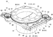
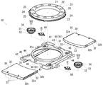
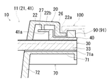
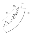
図1〜図5は、カップホルダ10の一実施例を示すものである。図1はカップホルダ10の外観を示す斜視図、図2はカップホルダ10の主要部についての分解斜視図、図3は図1のA−A線断面図、図4は操作部材20の凹凸形状26を示す図、図5はカップホルダ10の使用状態を示す図である。
本実施例のカップホルダ10は、図1に良く示されるように、有底で上面が開口形状とされるカップ保持具70の上部に、開口を同じくした開口部41(図2で示す円周状に形成された摺動部41a内)を有するリテイナー40が設けられて上面開口部11を形成している。また、図1及び図2に良く示されるように、この上面開口部11の開口周りには、透明性を有した(半透明の)樹脂製のリング状の操作部材20(中央の開口部21によって上面開口部11を形成している)が回動可能に配置されている。なお、本実施例においては、カップホルダ10全体としての開口部を表す概念として上面開口部11を用い、各構成要素に形成された単独の開口部を表す概念として開口部21,41を用いる。
更に、この操作部材20の両縁側には、半透明の操作部材20を照射する位置にLED91を配置したLEDモジュール90が設けられている。このLEDモジュール90は、夜間等の必要時に点灯されるイルミネーションランプに配線されて点灯される構成となっている。なお、LEDモジュール90は、これ以外にも、例えば、シガーライターのソケットを電源としたり、内蔵式の乾電池を電源とする構成にしたものであってもよい。ここで、LEDモジュール90が本発明の照射手段に相当する。
また、飲物容器80(図5参照)をカップホルダ10に載置するには、飲物容器80を上面開口部11内(操作部材20のリング内)に挿入すればよい。これにより、飲物容器80をカップ保持具70の底面の上に載置することができる。
Embodiments of the best mode for carrying out the present invention will be described below with reference to the drawings.
1 to 5 show an embodiment of the
As shown well in FIG. 1, the
Further, on both edge sides of the
In order to place the beverage container 80 (see FIG. 5) on the
次に、図2に良く示されるように、リテイナー40の案内部42内には、2部材から成る板状の蓋部材30が水平方向に挿入されている。また、これら蓋部材30に形成された歯部32aがリテイナー40の隅位置(2箇所)に回動可能に配置された歯車50の下側歯部52にそれぞれ連結されている。一方で、操作部材20の歯部23がこの歯車50の上側歯部51にそれぞれ連結されている。すなわち、操作部材20と蓋部材30とが歯車50に連結された構成となっている。
Next, as well shown in FIG. 2, a plate-
次に、半透明の操作部材20は、LED91からの照射を受けると、その光を透過する。したがって、この透過された光は、操作部材20の把持部22の上面22b側に現れるため、例えば夜間等の暗闇状態の場合にも、見る者に対してその位置を明確に指標することができる。すなわち、図3及び図4に良く示されるように、カップホルダ10の使用状態では、操作部材20以外の構成がコンソールボックスのアッパーパネル100に被覆されるため、操作部材20のみが車室内に対して露出した状態となる。したがって、LED91(光源)自体は車室内からは視認されず、操作部材20の上面22bなどの部位から透過した光が車室内から視認されることになる。
Next, when the
次に、上記カップホルダ10の詳細な構成について説明する。
先ず、半透明のリング状の操作部材20は、図1及び図2に良く示されるように、中央に形成された開口部21と、使用時に手動操作を行う部位とされる把持部22と、把持部22の外周縁に形成された歯部23と、鍔部25と、を有して構成されている。詳しくは、歯部23は、把持部22の外周縁に沿って円弧状に2箇所形成されている。また、歯部23が形成されたその他の外周縁部位には、鍔部25が形成されており、その端側部位には切欠き部24が形成されている。この切欠き部24は、操作部材20をリテイナー40に装着する際の嵌め入れ部位として機能する。すなわち、操作部材20の切欠き部24をリテイナー40に形成された嵌合爪44に嵌め入れて回動させると、嵌合爪44が鍔部25に嵌合して鍔部25の厚み方向への移動を規制する。なお、操作部材20は、図3に良く示されるように、内部に形成された突出部位27がリテイナー40の摺動面41aに当接状態とされており、操作部材20の回動操作を行うと、この突出部位27が摺動面41a上を摺動する。このようにして、操作部材20がリテイナー40に対して回動可能に配置されている。
Next, a detailed configuration of the
First, as shown in FIGS. 1 and 2, the translucent ring-shaped
また、図3及び図4に良く示されるように、把持部22の内側側面22aには、この円弧方向(操作部材20の回動方向)にわたって凹凸形状26が複数設けられている。したがって、操作部材20の回動操作を行うことにより、これら凹凸形状26がLED91(照射位置)を順に通過する。このとき、照射された際の光の透過量は、凹凸形状26のそれぞれの厚みの違いによって異なる。したがって、操作部材20の回動操作を行うと、この回動運動に伴って操作部材20を透過する光の明るさが変化する。
より詳しく述べると、凹凸形状26の起伏量は不規則的な多段階となるように設定されている。したがって、照射された際の光の透過量(明暗)は、それぞれの凹凸による厚みの違いによって多段階に異なることになる。また、起伏が不規則的となるように配列されていることから、光の明暗は常に段階的には推移せず、バラついて現れる(変化する)ことになる。
更に、凹凸形状26は、その円弧方向の長さが不規則的な多段階となるように設定されている。したがって、円弧方向の長さが多段階であることから、例えば、操作部材20を一定の回動速度で回動操作しても、光の明るさの変化するタイミングが多段階となる。また、円弧方向の長さが不規則的となるように配列されていることから、光の明るさの変化するタイミングが常に段階的には推移せず、バラついて変化する。
ところで、上述した操作部材20の歯部23自体の形状も円弧方向にわたって凹凸形状となっている。したがって、LEDモジュール90の配置によっては、この歯部23が、操作部材20の回動操作時にLED91を順に通過し、透過する光の明るさが変化する場合がある。
3 and 4, a plurality of concave and
More specifically, the undulation amount of the concavo-
Furthermore, the concavo-
By the way, the shape of the
次に、図1及び図2に良く示されるように、歯車50は、上側歯部51と下側歯部52とから成り、前述したように上側歯部51が操作部材20の歯部23にそれぞれ噛合わせ状態とされている。したがって、操作部材20の回動操作を行うことで、これら噛合わせ状態にある2つの歯車50は、同時に回動(同一方向に)する。また、2つの歯車50のそれぞれには、ギヤダンパー60が接続されており、回動運動時に一定の抵抗力が付与されるようになっている。
Next, as well shown in FIGS. 1 and 2, the
次に、図1及び図2に良く示されるように、板状に形成された2つの蓋部材30は、リテイナー40の案内部42内において摺動可能状態で配置されている。詳しくは、蓋部材30の横縁側部位32には歯部32aが形成されており、前述した歯車50の下側歯部52と噛合わせ状態とされている。更に、横縁側部位32のその他の部位には歯部32aと突出量の等しい凸部32bが複数形成されており、これら凸部32bがリテイナー40の案内部42に当接状態とされる。更に、蓋部材30の下面には横縁側部位32の形成方向に凸条33が複数形成されており、図3に良く示されるように、後述するカップ保持具70の案内部71に形成された凹条71aに対して、それぞれが緩やかに嵌合する構成とされている。
Next, as well shown in FIGS. 1 and 2, the two
したがって、操作部材20の回動操作によって歯車50が回動運動すると、この回動力が蓋部材30の水平方向移動運動に変換される。詳しくは、蓋部材30は共に水平方向移動運動を行って相対的に接近方向または離間方向に移動する。ここで、2つの蓋部材30の前縁側部位31は、互いに突合されて嵌合する曲面形状とされている。したがって、操作部材20の回動操作(閉操作)を行うと、蓋部材30の前縁側部位31が接近して突合されるため、上面開口部11が閉鎖状態となる。このとき、図1に良く示されるように、蓋部材30の上面に形成された係止爪34がリテイナー40に形成された係止溝43に係合してストッパーとしての機能を果たす。なお、操作部材20を反対方向に回動させれば、蓋部材30が相対的に離間方向に移動するため、上面開口部11が開放状態となる。このような簡単な操作(操作部材20の回動操作)によって、カップホルダ10の開閉操作が行える。
Therefore, when the
次に、リテイナー40は、図2に良く示されるように、中央に形成された開口部41と、上述した蓋部材30を案内する案内部42と、蓋部材30の係止爪34に係合する係止溝43と、を有して構成されている。また、上面には嵌合爪44が2箇所に形成されており、嵌め入れた操作部材20の鍔部25の厚み方向への移動を規制するようになっている。更に、操作部材20の両縁側となる位置にLEDモジュール90を固定している。詳しくは、LED91が操作部材20を照射するようにして配置されている。
次に、カップ保持具70は、図3に良く示されるように、蓋部材30の凸条33に緩やかに嵌合して案内する凹条71aが形成された案内部71と、飲物容器80を載置する底面を有した保持部72と、を有して構成されている。なお、カップ保持具70は、図3に良く示されるように、リテイナー40に対して一体的に固定されている。
Next, as shown well in FIG. 2, the
Next, as shown well in FIG. 3, the
続いて、本実施例のカップホルダ10の使用方法について説明する。
本実施例のカップホルダ10は、図3及び図5に良く示されるように、アッパーパネル100にリング状の操作部材20が露出した状態で配置されている。また、LED91は点灯状態とされており、操作部材20を両縁側から照射している。したがって、照射された光は、半透明の操作部材20を透過して、把持部22の上面22b側に現れる。このとき、LED91から照射された光は、操作部材20に形成された凹凸形状26によって明暗がぼやけて現れる。
次に、カップホルダ10の上面開口部11(開口状態)に飲物容器80をセットする。そして、飲物容器80の胴部の径が上面開口部11の径よりも小さい場合には、リング状の操作部材20の回動操作を行って、2つの蓋部材30を相対的に接近方向に移動させる。
このとき、操作部材20の回動運動に伴って、把持部22の内側側面22aに形成された凹凸形状26が順にLED91(照射位置)を通過する。これにより、LED91から照射される光は、起伏量が不規則的な多段階となるように設定された凹凸形状26によって、不規則的で、かつ、多段階に明暗を繰返すようにして変化する。更に、凹凸形状26は、操作部材20の回動方向の長さが不規則的な多段階となるように設定されているため、操作部材20の回動操作を一定速度で行っても、光の明るさの変化するタイミングが不規則的で、かつ、多段階となる。
このような回動操作によって、2つの蓋部材30を飲物容器80の胴部に当接させて保持状態とすることができる。また、カップホルダ10の上面開口部11を再び開口状態にする場合には、操作部材20を前述した回動方向とは反対方向に回動させればよい。これにより、前述した場合と同様にして、操作部材20の回動運動に伴って、LED91から照射される光の明るさが多様に変化する。
Then, the usage method of the
The
Next, the
At this time, as the operating
By such a rotation operation, the two
このように、本実施例のカップホルダ10は、半透明に形成されたリング状の操作部材20の回動操作を行うと、把持部22の内側側面22aに形成された凹凸形状26によって、LED91から照射された光の透過量(明暗)を様々に変化させることができる。すなわち、このような簡単な構成(凹凸形状26を形成した構成)によって、操作部材20の回動操作時におけるカップホルダ10の見栄えに変化を与えることができる。したがって、単にLED91による照射によってカップホルダ10の位置を指標するに留まらず、操作部材20の回動操作に伴う光の明るさの変化による面白さを演出することができる。
具体的には、凹凸形状26の起伏量が多段階となるように設定されているため、操作部材20の回動操作を行うと、LED91から照射された光を煌かせるようにして演出することができる。また、この起伏が不規則的となるように配置される設定となっているため、不均斉な光の演出が行える。更に、凹凸形状26の回動方向の長さが多段階となるように設定されているため、光の明るさの変化するタイミングを多段階に変化させて演出することができる。更に、凹凸形状26の回動方向の長さは、不規則的となるように配置される設定となっているため、不均斉な光の演出を一層引き立たせることができる。
As described above, when the cup-shaped
Specifically, since the undulation amount of the concavo-
以上、本発明の実施形態を1つの実施例について説明したが、本発明は上記実施例のほか各種の形態で実施できるものである。
例えば、本実施例においては、把持部22の内側側面22aに凹凸形状26を形成したものを示したが、この凹凸形状26は、把持部22の上面22bの内側に形成したものであっても良い。また、操作部材20の鍔部25(操作部の外側側面)に形成しても良い。この場合であっても、使用状態においては、これら凹凸形状が把持部22やアッパーパネル100によって被覆されるため、見栄えが損なわれない。
また、本実施例においては、凹凸形状26の起伏が不規則的となるように配置されたものを示したが、規則的となるように配置されたものでもよい。この場合であっても、明暗が段階的に推移するなどして、一定の演出効果が得られる。更に、凹凸形状26の回動方向の長さが不規則的となるように配置されたものを示したが、規則的となるように配置された場合であっても、一定の演出効果が得られる。その他にも、凹凸形状をしぼ状に形成したものであっても良い。
更に、LED91の配置を操作部材20の両縁側に1つずつ配置したものを示したが、この配置位置や数量は特に限定されるものではなく、使用用途に合わせて適宜決定すればよい。なお、本実施例の如く対向する2箇所にLED91を配置する(均等に配置する)と、リング上の操作部材20の操作時に満遍なく光を照射することができる。
Although the embodiment of the present invention has been described with respect to one example, the present invention can be implemented in various forms in addition to the above-described example.
For example, in the present embodiment, the concave and
In the present embodiment, the
Furthermore, although the
10 カップホルダ
11 上面開口部
20 操作部材
21 開口部
22 把持部
22a 内側側面
22b 上面
23 歯部
24 切欠き部
25 鍔部
26 凹凸形状
27 突出部位
30 蓋部材
31 前縁側部位
32 横縁側部位
32a 歯部
32b 凸部
33 凸条
34 係止爪
40 リテイナー
41 開口部
41a 摺動面
42 案内部
43 係止溝
44 嵌合爪
50 歯車
51 上側歯部
52 下側歯部
60 ギヤダンパー
70 カップ保持具
71 案内部
71a 凹条
72 保持部
80 飲物容器
90 LEDモジュール(照射手段)
91 LED
100 アッパーパネル
DESCRIPTION OF
91 LED
100 upper panel
Claims (6)
前記操作部材は透明性を有する素材によって形成され、照射時の光道となる所定箇所には凹凸形状が形成されており、
前記操作部材の回動操作を行うと、この回動運動に伴って、前記所定箇所に形成された凹凸形状が順に照射位置を通過する構成となっていることを特徴とするカップホルダ。 A cup holder for irradiating a ring-shaped operation member arranged to be rotatable around an opening of an upper surface opening for inserting a beverage container by means of irradiation means arranged at a predetermined location,
The operation member is formed of a transparent material, and a concavo-convex shape is formed at a predetermined position that becomes a light path at the time of irradiation,
When the operation member is rotated, the cup holder is configured such that the uneven shape formed at the predetermined location sequentially passes through the irradiation position along with the rotation.
前記操作部材の所定箇所に形成された凹凸形状は、該操作部材の回動方向にわたって複数設けられていることを特徴とするカップホルダ。 The cup holder according to claim 1,
A cup holder, wherein a plurality of concave and convex shapes formed at predetermined positions of the operation member are provided over the rotation direction of the operation member.
前記操作部材の所定箇所に形成された凹凸形状の起伏量が多段階となるように設定されていることを特徴とするカップホルダ。 The cup holder according to claim 2,
A cup holder, wherein the undulation amount of the concavo-convex shape formed at a predetermined location of the operation member is set to be multistage.
前記所定箇所に形成された凹凸形状の起伏量は不規則的な多段階となるように設定されていることを特徴とするカップホルダ。 The cup holder according to claim 3,
The cup holder, wherein the undulation amount of the concavo-convex shape formed at the predetermined location is set to be irregular and multistage.
前記操作部材の所定箇所に形成された凹凸形状の回動方向の長さが多段階となるように設定されていることを特徴とするカップホルダ。 A cup holder according to any one of claims 2 to 4,
A cup holder characterized in that the length of the concavo-convex shape formed in a predetermined position of the operation member in a rotational direction is set in multiple stages.
前記所定箇所に形成された凹凸形状の回動方向の長さは不規則的な多段階となるように設定されていることを特徴とするカップホルダ。
The cup holder according to claim 5,
A cup holder characterized in that the length of the concavo-convex shape formed in the predetermined portion in the rotational direction is set to be irregular and multistage.
Priority Applications (1)
| Application Number | Priority Date | Filing Date | Title |
|---|---|---|---|
| JP2004118080A JP2005297811A (en) | 2004-04-13 | 2004-04-13 | Cup holder |
Applications Claiming Priority (1)
| Application Number | Priority Date | Filing Date | Title |
|---|---|---|---|
| JP2004118080A JP2005297811A (en) | 2004-04-13 | 2004-04-13 | Cup holder |
Publications (1)
| Publication Number | Publication Date |
|---|---|
| JP2005297811A true JP2005297811A (en) | 2005-10-27 |
Family
ID=35329876
Family Applications (1)
| Application Number | Title | Priority Date | Filing Date |
|---|---|---|---|
| JP2004118080A Pending JP2005297811A (en) | 2004-04-13 | 2004-04-13 | Cup holder |
Country Status (1)
| Country | Link |
|---|---|
| JP (1) | JP2005297811A (en) |
Cited By (2)
| Publication number | Priority date | Publication date | Assignee | Title |
|---|---|---|---|---|
| CN104736389A (en) * | 2012-08-31 | 2015-06-24 | 江森自控科技公司 | Illuminated cup holder assembly |
| CN104797457A (en) * | 2012-11-19 | 2015-07-22 | 株式会社丰田自动织机 | Cup holder for vehicle |
Citations (3)
| Publication number | Priority date | Publication date | Assignee | Title |
|---|---|---|---|---|
| JPH0311598U (en) * | 1989-06-15 | 1991-02-05 | ||
| JP2001311947A (en) * | 1992-07-06 | 2001-11-09 | Omron Corp | Liquid crystal display |
| JP2002144941A (en) * | 2000-11-07 | 2002-05-22 | Nifco Inc | Cup holder |
-
2004
- 2004-04-13 JP JP2004118080A patent/JP2005297811A/en active Pending
Patent Citations (3)
| Publication number | Priority date | Publication date | Assignee | Title |
|---|---|---|---|---|
| JPH0311598U (en) * | 1989-06-15 | 1991-02-05 | ||
| JP2001311947A (en) * | 1992-07-06 | 2001-11-09 | Omron Corp | Liquid crystal display |
| JP2002144941A (en) * | 2000-11-07 | 2002-05-22 | Nifco Inc | Cup holder |
Cited By (4)
| Publication number | Priority date | Publication date | Assignee | Title |
|---|---|---|---|---|
| CN104736389A (en) * | 2012-08-31 | 2015-06-24 | 江森自控科技公司 | Illuminated cup holder assembly |
| CN104736389B (en) * | 2012-08-31 | 2017-03-08 | 江森自控科技公司 | Luminous glass stand assembly |
| CN104797457A (en) * | 2012-11-19 | 2015-07-22 | 株式会社丰田自动织机 | Cup holder for vehicle |
| CN104797457B (en) * | 2012-11-19 | 2016-12-14 | 株式会社丰田自动织机 | Vehicle glass stand |
Similar Documents
| Publication | Publication Date | Title |
|---|---|---|
| US8235567B2 (en) | Illuminated interior trim component | |
| KR20150086402A (en) | Cup holder | |
| US6824290B2 (en) | Illumination device | |
| EP2251882B1 (en) | Operating device with illumination function | |
| JP2005212755A (en) | Outside mirror device for vehicle | |
| US10272835B2 (en) | Illumination device for a cup holder in a vehicle | |
| US20120327674A1 (en) | Vehicle visor having hidden light assembly | |
| JP2005297811A (en) | Cup holder | |
| US7195380B2 (en) | Interior illumination lamp | |
| KR200484557Y1 (en) | Sun Visor for Vehicle With Mood Lighting | |
| JP2009062740A (en) | Door handle device for vehicle | |
| CN107101147A (en) | Car lighting assembly with the retractable covering for providing daytime running lamps | |
| JP2010132201A (en) | Vessel holder | |
| JP4075399B2 (en) | Lighting device | |
| JP7741763B2 (en) | Vehicle interior lighting system | |
| JP3969015B2 (en) | Room lamp | |
| WO2016031296A1 (en) | Vehicle interior illumination device | |
| JP6478216B2 (en) | LIGHTING DEVICE AND VEHICLE LIGHTING DEVICE | |
| JP2002096686A (en) | Console box structure | |
| JP4455142B2 (en) | Lighting structure of operation panel | |
| CN220314865U (en) | Automobile reading lamp | |
| JP4265441B2 (en) | Interior lighting device | |
| KR101664566B1 (en) | Mode lighting for sunglasses case using spot lamp | |
| US7476012B2 (en) | Vehicle interior lighting system | |
| JP5599700B2 (en) | Transparent illumination parts and decorative members for transparent illumination parts |
Legal Events
| Date | Code | Title | Description |
|---|---|---|---|
| A621 | Written request for application examination |
Free format text: JAPANESE INTERMEDIATE CODE: A621 Effective date: 20061016 |
|
| A977 | Report on retrieval |
Free format text: JAPANESE INTERMEDIATE CODE: A971007 Effective date: 20090324 |
|
| A131 | Notification of reasons for refusal |
Free format text: JAPANESE INTERMEDIATE CODE: A131 Effective date: 20091208 |
|
| A02 | Decision of refusal |
Free format text: JAPANESE INTERMEDIATE CODE: A02 Effective date: 20100406 |