JP2005297793A - Air conditioner - Google Patents
Air conditioner Download PDFInfo
- Publication number
- JP2005297793A JP2005297793A JP2004117559A JP2004117559A JP2005297793A JP 2005297793 A JP2005297793 A JP 2005297793A JP 2004117559 A JP2004117559 A JP 2004117559A JP 2004117559 A JP2004117559 A JP 2004117559A JP 2005297793 A JP2005297793 A JP 2005297793A
- Authority
- JP
- Japan
- Prior art keywords
- passage
- air
- outlet
- mode
- passages
- Prior art date
- Legal status (The legal status is an assumption and is not a legal conclusion. Google has not performed a legal analysis and makes no representation as to the accuracy of the status listed.)
- Pending
Links
- 238000007664 blowing Methods 0.000 claims abstract description 69
- 238000011144 upstream manufacturing Methods 0.000 claims abstract description 29
- 238000004378 air conditioning Methods 0.000 claims description 40
- 238000009423 ventilation Methods 0.000 description 12
- 239000000203 mixture Substances 0.000 description 8
- 238000005192 partition Methods 0.000 description 3
- 238000010586 diagram Methods 0.000 description 2
- 230000004048 modification Effects 0.000 description 2
- 238000012986 modification Methods 0.000 description 2
- 239000012141 concentrate Substances 0.000 description 1
- 238000010079 rubber tapping Methods 0.000 description 1
Images

Landscapes
- Air-Conditioning For Vehicles (AREA)
Abstract
Description
この発明は、車両等に用いられる空調装置にあって、異なる吹出モードを構成するように設けられた吹出通路が隣接して設けられている車両用空調装置に関する。 The present invention relates to an air conditioner used in a vehicle or the like, and relates to a vehicle air conditioner in which an outlet passage provided so as to constitute different outlet modes is provided adjacently.
車巾方向の中央部に配置される所謂センター置きの空調装置においては、車巾方向の中央部に配置されるオーディオ等の車載部品との干渉を避けつつ、ベント用吹出開口(センタベント用吹出開口、サイドベント用吹出開口)へ空気を供給する吹出通路を確保する必要がある。このため、従来においては、特許文献1又は2に示されるように、空調ケースの上部両脇にセンタベント用吹出開口とサイドベント用吹出開口とを設けるようにした車両用空調装置が提案されている。
In the so-called center-placed air conditioner arranged in the center in the vehicle width direction, the vent outlet opening (center vent outlet) is avoided while avoiding interference with in-vehicle components such as audio arranged in the center in the vehicle width direction. It is necessary to secure a blowing passage for supplying air to the opening and the side vent blowing opening). For this reason, conventionally, as shown in
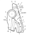
この車両用空調装置は、具体的には、図5及び図6に示されるような構成を有するもので、内部に空気流路2が形成された空調ケース3内に、エバポレータ4とエアミックスドア7にて通風量が調節されるヒータコア5とを車両の前後方向に配置し、エバポレータ4の上方に設けられた送風機6を回転させることで、空調ケース3内に導入された空気をエバポレータ4及びヒータコア5によって適宜温調した後に空調ケース3の上部に設けられた吹出モード切替手段へ供給するようになっている。
Specifically, this vehicle air conditioner has a configuration as shown in FIGS. 5 and 6, and an
エバポレータ4、ヒータコア5、及びエアミックスドア7によって構成される温調手段の下流側には、フロントガラスへ向けて空気を吹き出すデフロスト用吹出開口10、車室上方へ空気を吹き出すセンタベント用吹出開口11及びサイドベント用吹出開口12、車室下方へ空気を吹き出すフット用吹出開口13が形成されている。センタベント用吹出開口11は、エアミックスドア7の上方において空気流路2に臨むよう空調ケース2の車室側に向けられる側壁上部に形成され、デフロスト用吹出開口10及びサイドベント用吹出開口12は、空気流路2の最下流端に位置する空調ケース2の上部に形成されている。また、フット用吹出開口13は、フット用吹出通路2cを介して空調ケース3の車室側に向けられる側面の下端部に形成されている。
On the downstream side of the temperature control means constituted by the
そして、空調ケース内には、センタベント用吹出開口11へ温調空気を供給する通路(センタベント用吹出通路14)とサイドベント用吹出開口12へ温調空気を供給する通路(サイドベント用吹出通路15)とが温調手段よりも下流側で空気流路の左右両側のそれぞれに隣接して形成され、これらセンタベント用吹出通路14とサイドベント用吹出通路15とは、温調手段の風下側で空気流路と連通する部分がオーバラップしており、吹出通路の一部を共用するように形成されている。また、左右両側のサイドベント用吹出通路15間には、デフロスト用吹出開口10へ温調空気を供給する通路(デフロスト用吹出通路16)が形成されている。
In the air conditioning case, a passage for supplying temperature-controlled air to the center vent outlet opening 11 (center vent outlet passage 14) and a passage for supplying temperature-controlled air to the side vent outlet opening 12 (side vent outlet) 15) are formed downstream of the temperature control means and adjacent to the left and right sides of the air flow path. The center
したがって、このような構成においては、センタベント用吹出開口11とサイドベント用吹出開口12とに温調空気を供給する場合には、温調手段で温調された空気は、一旦、サイドベント用吹出通路15を兼ねるセンタベント用吹出通路14に集中して入り、その一部がセンタベント用吹出開口11へ供給され、残りが分岐されたサイドベント用吹出通路15を介してサイドベント用吹出開口12へ供給されるようになっている。
Therefore, in such a configuration, when temperature-controlled air is supplied to the center vent outlet opening 11 and the side vent outlet opening 12, the temperature-controlled air is temporarily used for the side vent. A side vent outlet opening 15 is formed through the center vent outlet opening 11 which is concentrated in the center
このように、上述のような構成においては、デフロスト用吹出通路16が閉塞され、センタベント用吹出開口11とサイドベント用吹出開口12とが開放された状態にすると、図7において模式的に示されるように、上流側から送られてくる空気は、両脇のセンタベント用吹出通路14及びサイドベント用吹出通路15に集中するので、デフロスト用吹出通路16を閉塞するドアαの上流側近傍に無駄な領域Aが形成され、また、この領域Aにおいて空気の乱流が生じ、スムーズな空気の流れが妨げられて通気抵抗が増大する不都合があった。また、センタベント用吹出開口11へ通じる通路(センタベント用吹出通路14)とサイドベント用吹出開口12へ通じる通路(サイドベント用吹出通路15)とが、温調手段の風下側でオーバラップして連通しているので、それぞれの吹出通路に対して十分な通路面積が確保されず、このような理由からも通気抵抗が大きくなって騒音が増大するなどの不都合が生じている。
Thus, in the configuration as described above, when the
そこで、この発明においては、異なる吹出モードを構成するように設けられた吹出通路が隣接して設けられている車両用空調装置において、通路抵抗の低減を図ると共に騒音の低減を図ることを主たる課題としている。 Therefore, in the present invention, in a vehicle air conditioner in which air outlets provided so as to constitute different air outlet modes are provided adjacent to each other, it is a main object to reduce passage resistance and reduce noise. It is said.
上記課題を達成するために、この発明に係る車両用空調装置は、少なくとも3つの吹出通路を車幅方向に配設し、中央部の吹出通路がその両側の吹出通路と異なる吹出モードを構成するために設けられ、前記中央部の吹出通路と前記両側のそれぞれの吹出通路との分岐部分に回転ドアを設け、この2つ回転ドアにより、前記中央部の吹出通路へ流れる風と前記両側の吹出通路へ流れる風との割合を調節し、前記中央部の吹出通路を閉塞する際に前記2つの回転ドアのそれぞれの先端部を風の流方向の上流側で近接させると共に、前記中央部の吹出通路と前記両側の吹出通路との一方を前記2つの回転ドアにより閉塞する際に、前記中央部の吹出通路と前記両側の吹出通路との他方へ上流側から導かれる風を前記回転ドアにより鈍角に変化させるようにしたことを特徴としている(請求項1)。 In order to achieve the above object, an air conditioner for a vehicle according to the present invention has at least three outlet passages arranged in the vehicle width direction, and the outlet passage in the center portion forms an outlet mode different from the outlet passages on both sides thereof. A rotating door is provided at a branch portion between the outlet passage in the central portion and the outlet passages on both sides, and the two rotating doors cause the wind flowing into the outlet passage in the central portion and the outlets on the both sides. The ratio of the wind flowing into the passage is adjusted, and when closing the blowout passage in the central portion, the respective leading ends of the two revolving doors are brought close to each other on the upstream side in the wind flow direction, and the blowout of the central portion When one of the passage and the blowout passages on both sides is closed by the two revolving doors, the obtuse angle of the wind guided from the upstream side to the other of the blowout passages in the central portion and the blowout passages on both sides by the revolving doors. To change Is characterized in that the the like (claim 1).
したがって、中央部の吹出通路を閉塞する際にそれぞれの回転ドアの先端部を風の流方向の上流側で近接させるようにしたので、これらドアの上流側で無駄な領域が低減される。また、中央部の吹出通路と両側の吹出通路との一方が回転ドアにより閉塞された場合には、上流側から導かれた風は回転ドアにより鈍角に変化して中央部の吹出通路と両側の吹出通路との他方へ導かれるので、開口している吹出通路へスムーズに風が導かれることになる。 Therefore, when closing the outlet passage in the central portion, the front end portions of the respective rotary doors are brought close to each other on the upstream side in the wind flow direction, so that a useless area is reduced on the upstream side of these doors. In addition, when one of the blowout passage in the central portion and the blowout passages on both sides is blocked by the revolving door, the wind guided from the upstream side is changed to an obtuse angle by the revolving door, and the blowout passage in the central portion and Since the air is guided to the other side of the blowout passage, the wind is smoothly led to the blowout passage that is open.
さらに、両側の吹出通路の上流側に、他の吹出通路を設け、両側の吹出通路と他の吹出通路との分岐部分に回転ドアを設け、この回転ドアにより、他の吹出通路の開度調節を行うと共に、他の吹出通路へ上流側から導かれる風を鈍角に変化させるようにしてもよい(請求項2)。このような構成を付加することで、他の吹出通路がさらに設けられるような場合でも、通気抵抗の増加を伴わず、空気のスムーズな流れを形成することが可能となる。 Furthermore, another outlet passage is provided upstream of the outlet passages on both sides, and a rotary door is provided at a branch portion between the outlet passages on the both sides and the other outlet passages, and the opening degree of the other outlet passages is adjusted by this rotary door. In addition, the wind guided from the upstream side to another blowing passage may be changed to an obtuse angle (claim 2). By adding such a configuration, it is possible to form a smooth air flow without increasing the airflow resistance even when another blowout passage is further provided.
また、上記課題を達成するために、この発明に係る車両用空調装置は、空気流路が形成された空調ケースと、この空気流路を介して空気を送風する送風機と、前記空気流路を流れる空気の温度を調節する調節手段と、前記空調ケースの前記温調手段よりも風下側で前記空気流路に連通し、第1モード用吹出開口へ空気を供給する第1モード用吹出通路及び第2モード用吹出開口へ空気を供給する第2モード用吹出通路とが設けられている構成において、前記第1モード用吹出通路及び前記第2モード用吹出通路が前記空気流路に連通する部分を、ぞれぞれ吹出通路の最小通路断面を合計した面積以上の通路断面にて連通するように構成してもよい(請求項3)。 Moreover, in order to achieve the said subject, the vehicle air conditioner which concerns on this invention has the air conditioning case in which the air flow path was formed, the air blower which blows air through this air flow path, and the said air flow path. Adjusting means for adjusting the temperature of the flowing air; a first mode outlet passage that communicates with the air flow path on the leeward side of the temperature adjusting means of the air conditioning case and supplies air to the first mode outlet opening; In the configuration in which the second mode outlet passage for supplying air to the second mode outlet is provided, the first mode outlet passage and the second mode outlet passage communicate with the air flow path. May be configured to communicate with each other in a passage cross section that is equal to or larger than the total area of the minimum passage cross sections of the blowout passages.
したがって、第1モード用吹出通路と第2モード用吹出通路とが温調手段の風下側で連通する部分に十分な面積を確保することができるので、第1モード用吹出通路と第2モード用吹出通路とに温調空気を導く場合でも、通気抵抗が大きくなる不都合を避けることができ、また、空気流路との連通部分の通路面積を十分に確保できるので、風速を一定にすることが可能となる。 Therefore, a sufficient area can be secured in the portion where the first mode outlet passage and the second mode outlet passage communicate with each other on the leeward side of the temperature control means, so that the first mode outlet passage and the second mode outlet passage can be secured. Even when temperature-controlled air is led to the blowout passage, the disadvantage of increasing the airflow resistance can be avoided, and the passage area of the communication portion with the air flow path can be sufficiently secured, so that the wind speed can be made constant. It becomes possible.
ここで、第1モード用吹出通路と第2モード用吹出通路には温調手段を介して下方から供給される空気を導かれ、第1モード用吹出通路と第2モード用吹出通路とを上下方向に隣接して設ける構成にあっては、少なくとも一方の吹出通路を下方から供給される空気の流れが鈍角に変化するように傾斜させるとよい(請求項4)。このような構成によれば、下方から供給される温調空気の急激な流方向の変更がなくなるので、通気抵抗を一層低減することが可能となる。 Here, air supplied from below is guided to the first mode outlet passage and the second mode outlet passage via the temperature control means, and the first mode outlet passage and the second mode outlet passage are moved up and down. In the configuration provided adjacent to the direction, at least one of the blowout passages may be inclined so that the flow of air supplied from below changes to an obtuse angle. According to such a configuration, since the rapid change of the flow direction of the temperature-controlled air supplied from below is eliminated, the ventilation resistance can be further reduced.
また、第1モード用吹出通路と第2モード用吹出通路とは、空調ケースの左右両側に設けられ、左右に設けられた吹出通路間に第3モード用吹出開口へ空気を供給する第3モード用吹出通路を設け、この第3モード用吹出通路とこれに隣接する吹出通路を共通のドアにより開度制御するようにしてもよい(請求項5)。このような構成によれば、吹出通路毎にドアが配設される場合に比べてドアの枚数を減らすことが可能となり、通気抵抗の低減を図ることが可能となる。 The first mode outlet passage and the second mode outlet passage are provided on the left and right sides of the air conditioning case, and the third mode supplies air to the third mode outlet opening between the outlet passages provided on the left and right. A blowout passage may be provided, and the opening degree of the third mode blowout passage and the blowout passage adjacent thereto may be controlled by a common door (claim 5). According to such a configuration, it is possible to reduce the number of doors as compared with the case where a door is provided for each outlet passage, and it is possible to reduce the ventilation resistance.
以上述べたように、請求項1に係る発明によれば、少なくとも3つの吹出通路を車幅方向に配設し、中央部の吹出通路がその両側の吹出通路と異なる吹出モードを構成するために設けられ、前記中央部の吹出通路と前記両側のそれぞれの吹出通路との分岐部分に回転ドアを設け、この2つ回転ドアにより前記中央部の吹出通路へ流れる風と前記両側の吹出通路へ流れる風との割合を調節し、前記中央部の吹出通路を閉塞する際にそれぞれの回転ドアの先端部を風の流方向の上流側で近接させると共に、前記中央部の吹出通路と前記両側の吹出通路との一方を前記2つの回転ドアにより閉塞する際に、上流側から導かれる風を前記回転ドアにより鈍角に変化させて前記中央部の吹出通路と前記両側の吹出通路との他方へ導くようにしたので、上流側から供給される空気がスムーズに吹出通路へ導かれることとなり、通気抵抗が低減されて騒音の低減を図ることが可能となる。 As described above, according to the first aspect of the present invention, at least three outlet passages are arranged in the vehicle width direction, and the outlet passage in the center portion forms a different outlet mode from the outlet passages on both sides thereof. A revolving door is provided at a branch portion between the blowing passage in the central portion and the blowing passages on both sides, and the two revolving doors flow the wind flowing into the blowing passage in the central portion and the blowing passage on the both sides. When adjusting the ratio with the wind and closing the blowout passage in the central portion, the front ends of the respective revolving doors are brought close to each other on the upstream side in the flow direction of the wind, and the blowout passages in the central portion and the blowouts on the both sides When one of the passages is closed by the two revolving doors, the wind guided from the upstream side is changed to an obtuse angle by the revolving doors and led to the other of the blowout passages in the central portion and the blowout passages on both sides. Because Becomes the air supplied from the side is smoothly guided to the outlet passages, ventilation resistance is reduced and it is possible to reduce the noise.
さらに、請求項2に係る発明によれば、両側の吹出通路の上流側に、他の吹出通路が設けられ、前記両側の吹出通路と前記他の吹出通路との分岐部分に回転ドアを設け、この回転ドアにより、前記他の吹出通路の開度調節を行うと共に、上流側から導かれる風を鈍角に変化させて前記他の吹出通路へ導くようにしたので、他の吹出通路がさらに設けられるような場合でも、通気抵抗の増加を伴わず、風の流れをスムーズにすることが可能となり、騒音の増大を避けることが可能となる。
Furthermore, according to the invention according to
請求項3に係る発明によれば、空気流路が形成された空調ケースと、この空気流路を介して空気を送風する送風機と、前記空気流路を流れる空気の温度を調節する調節手段と、前記空調ケースの前記温調手段よりも風下側で前記空気流路に連通し、第1モード用吹出開口へ空気を供給する第1モード用吹出通路及び第2モード用吹出開口へ空気を供給する第2モード用吹出通路とが設けられている車両用空調装置において、前記第1モード用吹出通路及び前記第2モード用吹出通路が前記空気流路に連通する部分を、ぞれぞれ吹出通路の最小通路断面を合計した面積以上の通路断面としたので、それぞれの吹出通路が空気流路と連通する部分に独立の十分な通路面積を確保することが可能となり、通気抵抗を低減することができると共に、風速を均一化させて騒音の低減を図ることが可能となる。
According to the invention which concerns on
また、請求項4に係る発明によれば、第1モード用吹出通路と第2モード用吹出通路に温調手段を介して下方から供給される空気が導かれる場合に、第1モード用吹出通路と第2モード用吹出通路を上下方向に隣接して設け、少なくとも一方の吹出通路を下方から供給される空気の流れが鈍角に変化するように傾斜させたので、空気の大きな流方向の変更がなくなり、通気抵抗を一層低減することが可能となる。 According to the fourth aspect of the present invention, when air supplied from below is guided to the first mode outlet passage and the second mode outlet passage via the temperature control means, the first mode outlet passage is provided. And the second mode outlet passage are provided adjacent to each other in the vertical direction, and at least one of the outlet passages is inclined so that the flow of air supplied from below changes to an obtuse angle. The ventilation resistance can be further reduced.
さらに、請求項5に係る発明によれば、センタベント用吹出通路とサイドベント用吹出通路とを空調ケースの左右両側に設け、左右に設けられた吹出通路間にデフロスト用吹出開口へ空気を供給するデフロスト用吹出通路を設け、このデフロスト用吹出通路とこれに隣接する吹出通路を共通のドアにより開度制御するようにしたので、ドアの共用化を図ることができ、ドアの枚数を減らすことで通気抵抗の低減を図ることが可能となる。 According to the fifth aspect of the present invention, the center vent outlet passage and the side vent outlet passage are provided on both the left and right sides of the air conditioning case, and air is supplied to the defrost outlet opening between the left and right outlet passages. The defrost blowing passage and the blow passage adjacent to the defrost blowing passage are controlled by a common door so that the door can be shared and the number of doors can be reduced. This makes it possible to reduce the ventilation resistance.
以下、この発明の最良の実施形態を添付図面を参照しながら説明する。 DESCRIPTION OF THE PREFERRED EMBODIMENTS The best embodiment of the present invention will be described below with reference to the accompanying drawings.
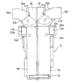
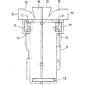
図1及び図2において、車両のセンターコンソール部に搭載されるセンター置きタイプの空調装置1が示されている。この空調装置1は、エンジンルームと車室とを区画する仕切板よりも車室側に配されているもので、内部に空気流路2が形成された空調ケース3に、エバポレータ4、ヒータコア5が車両の前後方向に配置されて収納されており、空調ケース3内のエバポレータ4の上部に送風機6が設けられ、この送風機6を回転させることで、送風機6と対峙して設けられた図示しないインテーク部を介して内気又は外気が空調ケース内に導入されるようになっている。
1 and 2 show a center-placed
エバポレータ4は、空調ケース3内において導入される全ての空気が通過するように立設され、また、ヒータコア5は、エバポレータ4よりも下流側(車室側)において空調ケース3の下部に立設されている。
The
ここで、空調ケース3は、エバポレータ4が載置されるロアケース部材3aと、このロアケース部材3aの上部に着脱自在に組み付けられた左右縦割りの2分割構造をなすアッパーケース部材3b、3cとを有して構成され、これらケース部材3a、3b、3cはタッピングスクリューなどを用いて結合されている。
Here, the air-
このように構成された空調ケース3内には、エバポレータ4を通過した空気をヒータコア5をバイパスして下流側へ導く冷風通路2aと、ヒータコア5を通過した空気を下流側へ導く温風通路2bとが形成されており、この冷風通路2aを通過する空気と、温風通路2bを通過する空気との割合がヒータコア5の上方に設けられたエアミックスドア7によって調節されるようになっている。このエアミックスドア7と前記エバポレータ4及びヒータコア5とによって送風機6から圧送された空気を温調する温調手段が形成されている。
In the
エアミックスドア7の下流側には、フロントガラスへ向けて空気を吹き出すデフロスト用吹出開口10、車室上方へ空気を吹き出すセンタベント用吹出開口11a,11b及びサイドベント用吹出開口12a,12b、車室下方へ空気を吹き出すフット用吹出開口13が形成されている。
On the downstream side of the
ここで、センタベント用吹出開口11a,11bは、エアミックスドア7の上方において空調ケース2の左右両側に延設された所定の最小通路断面S1を有するセンタベント用吹出通路14a,14bを介して温調手段の下流側に連通されているもので、空調ケース3の車室側に向けられる側壁の上部両側に形成されている。
Here, the center
また、サイドベント用吹出開口12a,12bは、空調ケース3の上部においてセンタベント用吹出通路14a,14bよりも下流側において左右両側へ延設された所定の最小通路断面S2を有するサイドベント用吹出通路15a,15bを介して温調手段の風下側に連通されているもので、空調ケース3の左右側方へ開口するように形成されている。
Also, the
ここで、センタベント用吹出通路14a,14b及びサイドベント用吹出通路15a,15bの最小通路面積とは、吹出開口に至る通路のうち、最も絞られた部分の通路断面をいう。
Here, the minimum passage area of the center
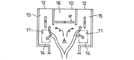
さらに、デフロスト用吹出開口10にあっては、左右のサイドベント用吹出通路15間に延設されたデフロスト用吹出通路16を介して空調ケース3の上部中央に形成されている。したがって、空調ケースの上部には、デフロスト用吹出通路16とその両側に設けられたサイドベント用吹出通路15a,15bとの3つの吹出通路が車幅方向に配設されており、中央部の吹出通路がその両側の吹出通路と異なる吹出モードを構成するために設けられている。
Further, the
また、フット用吹出開口13は、空調ケース3の車室側に向けられる側面の下端部に形成されており、空調ケース3内を上方へ延びる隔壁14によって画成されるフット用吹出通路2cを介してエアミックスドア7の下流側に連通している。
Further, the
そして、センタベント用吹出通路14とサイドベント用吹出通路15が温調手段の風下側で空気流路2に連通する部分は、それぞれの吹出通路の最小通路断面(S1,S2)を合計した面積(S1+S2)以上の通路断面にて連通されている。即ち、センタベント用吹出通路14が空気流路2に連通する部分とサイドベント用吹出通路15が空気流路2に連通する部分とがオーバラップしないように上下方向(空気の流方向)にずらして隣接形成されている。
The portion where the center
ここで、センタベント用吹出通路14は、温調手段の風下側の空気流路に対して略直角方向に延びるように形成され、また、サイドベント用吹出通路15は、温調手段を介して下方から供給される空気の流れが鈍角に変化するように傾斜して形成されている。
Here, the center
また、センタベント用吹出開口11は、空調ケース3の左右方向に架設された共通の回転軸20cを有するセンタベント用モードドア20a,20bにより開度調節され、デフロスト用吹出開口10とサイドベント用吹出開口12a,12bとは、デフロスト用吹出通路16とこれに隣接する両側のサイドベント用吹出通路15a,15bとを、これらの吹出通路のそれぞれの分岐部分に設けられ、空調ケース3の前後方向に架設された回転軸21c,21dを有するデフベント用モードドア21a,21bで開度制御することで供給風量が調節されるようになっている。
Further, the opening of the vent opening 11 for the center vent is adjusted by the center
このデフベント用モードドア21a,21bは、中央部のデフロスト用吹出通路16を閉塞する際にドアのそれぞれの先端部を風の流方向の上流側で突きあわせるように近接させると共に、デフロスト用吹出通路16とサイドベント用吹出通路15a,15bとの一方を2つのデフベント用モードドア21a,21bにより閉塞する際に、上流側から導かれる風をデフベント用モードドア21a,21bにより鈍角に変化させてデフロスト用吹出通路16とサイドベント用吹出通路15a,15bとの他方へ導くようにしている。
When the defrost
さらに、フット用吹出開口13は、フット通路2cの手前に配されたフット用モードドア22により供給風量が調節されるようになっている。これらセンタベント用モードドア20a,20b、デフベント用モードドア21a,21b、及びフット用モードドア22によって、吹出モード切替手段が構成されている。
Further, the air supply amount of the
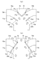
したがって、上流から導かれた風は、デフロスト用吹出通路16が閉塞され、センタベント用吹出開口11a,11bとサイドベント用吹出開口12a,12bとが開放された状態においては、図3(a)に示されるように、デフベント用モードドア21a,12bのそれぞれの先端部が近接して付き合わされるので、上流側から送られてくる空気は、デフベント用モードドア21a,21bに案内されつつサイドベント用吹出通路15a,15bへ鈍角に流方向が変更されて導かれるので、デフロスト用吹出通路16を閉塞するドアの上流側近傍に無駄なスペースが形成されることがなくなり、空気の乱流を防いでスムーズな流れを形成することが可能となる。このため、風速を一定にすることが可能になると共に、騒音の低減を図ることが可能となる。
Accordingly, the wind guided from the upstream side in the state where the
また、デフロスト用吹出通路16が開放され、センタベント用吹出開口11a,11bとサイドベント用吹出開口12a,12bとが閉塞された状態においては、図3(b)に示されるように、上流側から送られた空気が、デフベント用モードドア21a,21bに案内されつつデフロスト用吹出通路16へ鈍角に流方向が変更されて導かれるので、スムーズなデフロスト用吹出通路16への空気の流れが形成され、騒音の低減を図ることが可能となる。
When the
さらに、上述した構成においては、温調手段の風下側においてセンタベント用吹出通路14a,14bとサイドベント用吹出通路15a,15bとが、それぞれの吹出通路の最小通路断面を合計した面積以上の通路断面によって温調手段の風下側で空気流路2に連通されているので、センタベント用吹出通路14a,14bとサイドベント用吹出通路15a,15bとが温調手段の風下側で連通する部分に十分な面積を確保することが可能となり、センタベント用吹出開口11a,11bとサイドベント用吹出開口12a,12bとに温調空気を供給する場合でも、通気抵抗を小さく維持することが可能となり、風速を一定にすることが可能になると共に、騒音の低減を図ることが可能となる。
Furthermore, in the above-described configuration, the center
さらにまた、サイドベント用吹出通路15自体は下方から供給される空気の流れが鈍角に変化するように緩やかに傾斜しているので、下方から供給される温調空気の急激な流方向の変更を避けることが可能となり、通気抵抗の一層の低減を図ることが可能となる。さらにまた、デフロスト用吹出通路16とこれに隣接するサイドベント用吹出通路15a,15bを共通のモードドア(デフベントモードドア21)により開度制御するようにしたので、ドアの共用化を図ることができ、ドアの枚数を減らすことで通気抵抗の低減を図ることが可能となる。
Furthermore, since the side
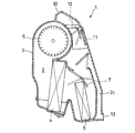
図4に、上述した構成の変形例が示されている。この構成においては、サイドベント用吹出開口12a,12bは、エアミックスドア7の上方において空調ケース2の左右両側に延設されたサイドベント用吹出通路15a,15bを介して温調手段の風下側に連通されている点で前記構成例と同様であるが、センタベント用吹出通路14a,14bは、サイドベント用吹出通路15a,15bの上流側に略平行に延設され、空調ケース3の左右側方へ開口するように形成されている点で異なっている。
FIG. 4 shows a modification of the above-described configuration. In this configuration, the
また、デフロスト用吹出通路16とこれに隣接する両側のそれぞれのサイドベント用吹出通路15a,15bとの分岐部分には、空調ケース3の前後方向に架設した回転軸21c,21dを有するデフベント用モードドア21a,21bが設けられ、このモードドアによりそれぞれの通路を開度を調節することで、デフロスト用吹出開口10とサイドベント用吹出開口12a,12bへの供給風量を調節している点で前記構成例と同様である。これに加えて、センタベント用吹出通路14a,14bとサイドベント用吹出通路15a,15bとの分岐部分に空調ケース3の前後方向に架設した回転軸23c,23dを有し、デフベント用モードドア21a,21bと連動して略平行となるセンタベント用モードドア23a,23bを設け、このモードドアによりセンタベント用吹出通路14a,14bを開度制御することでこの通路の供給風量を調節するようにしている。
Further, a defvent mode having
このセンタベント用モードドア23a,23bも、センタベント用吹出通路14a,14bが開放されるときには、上流側から導かれた空気の流方向が鈍角に変更されてセンタベント用吹出通路14a,14bに供給され、センタベント用吹出通路14a,14bが閉塞されるときには、上流側から導かれた空気の流方向が鈍角に変更されて、デフロスト用吹出通路16に供給されるようになっている。
In the center
このような構成例において、デフロスト用吹出通路16が閉塞され、センタベント用吹出開口11a,11bとサイドベント用吹出開口12a,12bとが開放された状態においては、図4(a)に示されるように、デフベント用モードドア21a,12bのそれぞれの先端部が近接して付き合わされると共に、センタベント用モードドア23a,23bがデフベント用モードドア21a,12bの上流側で間隔を開けてデフベント用モードドア21a,12bと略平行に突き出されるので、上流側から送られてくる空気は、センタベント用モードドア23a,23bに案内されつつ鈍角に流方向が変更されてセンタベント用吹出通路14a,14bに導かれ、センタベント用吹出開口11a,11bへ供給される。また、センタベント用モードドア23a,23b間を通過した空気は、デフベント用モードドア21a,21bに案内されつつ鈍角に流方向が変更されてサイドベント用吹出通路15a,15bへ導かれてサイドベント用吹出開口12a,12bへ供給される。このため、空気の乱流を形成することなく、スムーズに空気をセンタベント用吹出通路14a,14bとサイドベント用吹出通路15a,15bとへ導くことが可能となり、風速を一定にすると共に騒音の低減を図ることが可能となる。
In such a configuration example, when the
また、デフロスト用吹出通路16が開放され、センタベント用吹出開口11a,11bとサイドベント用吹出開口12a,12bとが閉塞された状態においては、図4(b)に示されるように、上流側から送られた空気が、センタベント用モードドア23a,23bとデフベント用モードドア21a,21bに案内されつつ鈍角に流方向が変更されてデフロスト用吹出通路16へ導かれるので、スムーズに空気をデフロスト用吹出通路16へ導くことが可能となり、騒音の低減を図ることが可能となる。
When the
尚、上述の構成においては、デフロスト用吹出通路16とその両側のサイドベント用吹出通路15a,15bとが車幅方向に並設された構成について説明したが、中央部の吹出通路がその両側の吹出通路と異なる吹出モードを構成するために設けられる少なくとも3つの吹出通路を車幅方向に配設する他の構成においても適用可能である。
In the above-described configuration, the
1 空調装置
2 空気流路
3 空調ケース
4 エバポレータ
5 ヒータコア
6 送風機
10 デフロスト用吹出開口
11a,11b センタベント用吹出開口
12a,12b サイドベント用吹出開口
14a,14b センタベント用吹出通路
15a,15b サイドベント用吹出通路
16 デフロスト用吹出通路
21a,21b デフベント用モードドア
23a,23b センタベント用モードドア
DESCRIPTION OF
Claims (5)
前記第1モード用吹出通路及び前記第2モード用吹出通路が前記空気流路に連通する部分を、ぞれぞれ吹出通路の最小通路断面を合計した面積以上の通路断面にしたことを特徴とする車両用空調装置。 An air conditioning case in which an air flow path is formed, a blower for blowing air through the air flow path, an adjusting means for adjusting the temperature of air flowing through the air flow path, and the temperature adjusting means of the air conditioning case A first mode outlet passage for supplying air to the first mode outlet opening and a second mode outlet passage for supplying air to the second mode outlet opening are also provided on the leeward side. In the vehicle air conditioner
The portion where the first mode outlet passage and the second mode outlet passage communicate with the air flow path has a passage cross section equal to or larger than the total area of the minimum passage cross sections of the outlet passages. A vehicle air conditioner.
Priority Applications (1)
| Application Number | Priority Date | Filing Date | Title |
|---|---|---|---|
| JP2004117559A JP2005297793A (en) | 2004-04-13 | 2004-04-13 | Air conditioner |
Applications Claiming Priority (1)
| Application Number | Priority Date | Filing Date | Title |
|---|---|---|---|
| JP2004117559A JP2005297793A (en) | 2004-04-13 | 2004-04-13 | Air conditioner |
Publications (1)
| Publication Number | Publication Date |
|---|---|
| JP2005297793A true JP2005297793A (en) | 2005-10-27 |
Family
ID=35329862
Family Applications (1)
| Application Number | Title | Priority Date | Filing Date |
|---|---|---|---|
| JP2004117559A Pending JP2005297793A (en) | 2004-04-13 | 2004-04-13 | Air conditioner |
Country Status (1)
| Country | Link |
|---|---|
| JP (1) | JP2005297793A (en) |
Cited By (1)
| Publication number | Priority date | Publication date | Assignee | Title |
|---|---|---|---|---|
| JP2017219272A (en) * | 2016-06-09 | 2017-12-14 | 中央精機株式会社 | Heat acoustic system |
-
2004
- 2004-04-13 JP JP2004117559A patent/JP2005297793A/en active Pending
Cited By (1)
| Publication number | Priority date | Publication date | Assignee | Title |
|---|---|---|---|---|
| JP2017219272A (en) * | 2016-06-09 | 2017-12-14 | 中央精機株式会社 | Heat acoustic system |
Similar Documents
| Publication | Publication Date | Title |
|---|---|---|
| KR101484712B1 (en) | Dual zone type air conditioner for vehicles | |
| JP4196492B2 (en) | Air conditioner for vehicles | |
| JP5545267B2 (en) | Air conditioner for vehicles | |
| EP1787836B1 (en) | Vehicular air conditioner | |
| KR20160067044A (en) | Dual zone type air conditioner for vehicle and its control method | |
| KR102319003B1 (en) | Air conditioner for vehicle | |
| JP4016496B2 (en) | Air conditioner for vehicles | |
| KR102182344B1 (en) | Air conditioner for vehicle | |
| US5890651A (en) | Air conditioning apparatus for vehicle | |
| JP2000255247A (en) | Vehicular air conditioner | |
| JP4178866B2 (en) | Air conditioner for vehicles | |
| JP2009269425A (en) | Vehicular air conditioner | |
| KR100759794B1 (en) | Automotive air conditioner with left and right independent control | |
| EP3578397A1 (en) | Air conditionning system for vehicle | |
| JP2005297793A (en) | Air conditioner | |
| JP7407429B2 (en) | Vehicle air conditioner | |
| KR20050111251A (en) | Air conditioner for vehicle | |
| JP5761952B2 (en) | Air conditioner for vehicles | |
| JP2008087575A (en) | Air conditioner for vehicles | |
| JPH11222021A (en) | Vehicle air conditioner | |
| JP2002362132A (en) | Air conditioner for vehicle | |
| JP4436020B2 (en) | Air conditioner for vehicles | |
| JP2007253689A (en) | Air conditioner for vehicle | |
| JP2006137345A (en) | Air conditioner for vehicle | |
| JP2007168619A (en) | Air blast switching device and air conditioner for automobile using the same |
Legal Events
| Date | Code | Title | Description |
|---|---|---|---|
| A621 | Written request for application examination |
Effective date: 20070404 Free format text: JAPANESE INTERMEDIATE CODE: A621 |
|
| A977 | Report on retrieval |
Free format text: JAPANESE INTERMEDIATE CODE: A971007 Effective date: 20090805 |
|
| A131 | Notification of reasons for refusal |
Free format text: JAPANESE INTERMEDIATE CODE: A131 Effective date: 20090818 |
|
| A02 | Decision of refusal |
Free format text: JAPANESE INTERMEDIATE CODE: A02 Effective date: 20091215 |