JP2005297760A - In-vehicle camera video transmission system - Google Patents
In-vehicle camera video transmission system Download PDFInfo
- Publication number
- JP2005297760A JP2005297760A JP2004116772A JP2004116772A JP2005297760A JP 2005297760 A JP2005297760 A JP 2005297760A JP 2004116772 A JP2004116772 A JP 2004116772A JP 2004116772 A JP2004116772 A JP 2004116772A JP 2005297760 A JP2005297760 A JP 2005297760A
- Authority
- JP
- Japan
- Prior art keywords
- connector
- imaging
- transmission
- camera
- wireless communication
- Prior art date
- Legal status (The legal status is an assumption and is not a legal conclusion. Google has not performed a legal analysis and makes no representation as to the accuracy of the status listed.)
- Pending
Links
Images


Landscapes
- Closed-Circuit Television Systems (AREA)
- Radio Relay Systems (AREA)
Abstract
【課題】自動車の周囲を撮像する撮像カメラからの映像を車室内に取り込むに際して、他の車両部品との干渉を容易に防ぐ。
【解決手段】撮像カメラ11とカメラ制御装置13との間のデータ伝送について、無線通信を行う無線通信手段15,17と、有線通信を行う伝送ケーブル19の各コネクタの形状を共通形状にし、これらの両方を撮像カメラ11及びカメラ制御装置13に対して交換可能に接続できるようにする。自動車において同一の撮像カメラ11及びカメラ制御装置13を設置する際に、無線通信と有線通信とを容易に転換して適用でき、これらのうちのいずれかを任意に選択し、他の車両部品との干渉を容易に防止することができる。
【選択図】図1
An object of the present invention is to easily prevent interference with other vehicle parts when capturing an image from an imaging camera that images the surroundings of an automobile into a passenger compartment.
For data transmission between an imaging camera 11 and a camera control device 13, wireless communication means 15 and 17 for performing wireless communication and a connector of a transmission cable 19 for performing wired communication have a common shape, and these Both of them can be connected to the imaging camera 11 and the camera control device 13 in an exchangeable manner. When installing the same imaging camera 11 and camera control device 13 in an automobile, it is possible to easily switch between wireless communication and wired communication, select any one of these, and select other vehicle parts. Can be easily prevented.
[Selection] Figure 1
Description
本発明は、車載カメラ映像伝送システム及びそれに関連する技術に関するものである。 The present invention relates to an in-vehicle camera video transmission system and a related technology.
自動車においては、図5の如く、その進行方向やその他の周囲の景観をCCD撮像素子等を利用した撮像カメラ1で撮像し、この撮像カメラ1で撮像された映像を、車室内のインストゥルメントパネル等に設置された表示装置3に表示することが行われている。この場合、撮像カメラ1と表示装置3との間は所定の伝送ケーブル5で接続されており、この伝送ケーブル5に映像信号を流すことで、撮像カメラ1からの映像が表示装置3に与えられる。
In an automobile, as shown in FIG. 5, the traveling direction and other surrounding scenery are imaged by an imaging camera 1 using a CCD imaging device or the like, and an image captured by the imaging camera 1 is taken as an instrument in the vehicle interior. The display is performed on the
尚、特許文献1のように、撮像カメラ1と表示装置3との間で無線通信を行う技術も公開されている。
As disclosed in Patent Document 1, a technique for performing wireless communication between the imaging camera 1 and the
一般に、自動車は電気系統だけでなく、エンジン系統や冷却系統の多くの部品が搭載されている。そして、これらの多くの部品は、重量バランスや機能効率化のために適宜最適な位置に配置される。かかる自動車において、撮像カメラ1と表示装置3との間を伝送ケーブル5で接続する場合、その伝送ケーブル5の配策は多くの車両部品のレイアウトによって制約を受ける。例えば、撮像カメラ1を自動車の前端部に設置する場合、通常は自動車の前端部と車室との間にはエンジン機構等の様々な車両部品が搭載されるため、これらの車両部品のレイアウトによって伝送ケーブル5の配策が制約を受けることになる。
In general, an automobile is equipped not only with an electric system but also with many parts of an engine system and a cooling system. Many of these components are appropriately arranged at optimal positions for weight balance and functional efficiency. In such an automobile, when the imaging camera 1 and the
ところで、量産によるコスト低減を行うために、撮像カメラ1と表示装置3とを規格化する必要があるが、このような規格化された撮像カメラ1及び表示装置3を様々な車種の自動車に搭載する場合、上述のように、車両部品のレイアウトによっては、伝送ケーブル5の配策が容易な場合と困難な場合とが生じ得る。即ち、撮像カメラ1と表示装置3とを接続する伝送ケーブル5は、電源用電線、グランド用電線、映像信号用電線の3本の電線が束ねられ、それらをシールドした上で被覆することから、通常の伝送ケーブル5はある程度の太さを持った線経を有して形成される。この場合、その曲率半径を小さくするのにはある程度の限界があるため、所望の目的で最適配置された車両部品を回避して伝送ケーブル5を屈曲することが困難になる場合が生じ得る。
By the way, in order to reduce the cost by mass production, it is necessary to standardize the imaging camera 1 and the
また、自動車によっては、図6のように、複数の撮像カメラ1a〜1dを設置し、それぞれの撮像カメラ1a〜1dで得られた映像を車室内の表示装置3に表示したい場合がある。この場合において、他の車両部品との干渉の問題から、一部の撮像カメラ1a〜1dについては伝送ケーブル5a〜5cでの有線接続が容易であるが、他の一部の撮像カメラ1a〜1dについては伝送ケーブル5a〜5cでの有線接続が困難になる場合も生じ得る。即ち、一台の自動車においても、一部の撮像カメラ1a〜1dを表示装置3に有線接続することが困難になり得る。
Further, as shown in FIG. 6, depending on the automobile, there are cases where a plurality of
その一方において、特許文献1のような無線通信を行う場合、外部から混入される電磁ノイズをどのように除去するかという問題もあり、電磁ノイズの混入を防いで伝送される信号の品質を維持したい場合に、電磁シールドが困難な部位が存在する場合には、一概に無線通信を行うことが困難な場合がある。特に、車両部品のレイアウトによっては、電波経路となる導波管を形成することが困難な場合があり、この場合には伝送ケーブル5の使用が望ましい場合もある。
On the other hand, when performing wireless communication as in Patent Document 1, there is also a problem of how to remove externally mixed electromagnetic noise, so that the quality of the transmitted signal is maintained while preventing the mixing of electromagnetic noise. If there is a part where electromagnetic shielding is difficult to be performed, it may be difficult to perform wireless communication in general. In particular, depending on the layout of the vehicle parts, it may be difficult to form a waveguide serving as a radio wave path. In this case, it may be desirable to use the
そこで、本発明の課題は、自動車の周囲を撮像する撮像カメラからの映像を車室内に取り込むに際して、車両環境に合わせて有線・無線の伝送方式を容易に選択できる車載カメラ映像伝送システムを提供することにある。 Accordingly, an object of the present invention is to provide an in-vehicle camera video transmission system that can easily select a wired / wireless transmission method in accordance with the vehicle environment when capturing an image from an imaging camera that captures the surroundings of the vehicle into the vehicle interior. There is.
上記課題を解決すべく、請求項1に記載の発明は、自動車の周囲を撮像するための撮像手段と、前記撮像手段の映像信号を受信する撮像制御手段との間のデータ伝送を行う車載カメラ映像伝送システムにおいて、前記撮像手段と前記撮像制御手段との間に接続可能に構成されてそれらの間のデータ伝送を無線により行う第1の伝送手段と、前記第1の伝送手段に代えて前記撮像手段と前記撮像制御手段との間に接続可能に構成されてそれらの間のデータ伝送を有線により行う第2の伝送手段とを備えたものである。 In order to solve the above-mentioned problem, the invention according to claim 1 is a vehicle-mounted camera that performs data transmission between an image pickup means for picking up an image around a vehicle and an image pickup control means for receiving a video signal of the image pickup means. In the video transmission system, a first transmission unit configured to be connectable between the imaging unit and the imaging control unit and wirelessly transmitting data therebetween, and the first transmission unit instead of the first transmission unit A second transmission unit configured to be connectable between the imaging unit and the imaging control unit and performing data transmission between them by wire is provided.
請求項2に記載の発明は、請求項1に記載の車載カメラ映像伝送システムであって、前記撮像手段に第1のコネクタが形成されるとともに、前記撮像制御手段に第2のコネクタが形成され、前記第1の伝送手段が、前記第1のコネクタに接続可能なコネクタを有する第1の無線通信部と、前記第2のコネクタに接続可能なコネクタを有して前記第1の無線通信部と無線通信を行う第2の無線通信部とを備え、前記第2の伝送手段が、伝送ケーブルの一端に、前記第1のコネクタに接続可能なコネクタが形成されるとともに、他端に、前記第2のコネクタに接続可能なコネクタが形成されてなるものである。 A second aspect of the present invention is the in-vehicle camera video transmission system according to the first aspect, wherein a first connector is formed on the image pickup means and a second connector is formed on the image pickup control means. The first transmission means includes a first wireless communication unit having a connector connectable to the first connector, and a connector connectable to the second connector. And a second wireless communication unit for performing wireless communication, and the second transmission means is formed with a connector connectable to the first connector at one end of the transmission cable, and at the other end, the A connector connectable to the second connector is formed.
請求項3に記載の発明は、請求項2に記載の車載カメラ映像伝送システムであって、前記撮像制御手段の一部に、前記第2の無線通信部を収納するための収納空間が形成され、当該収納空間の奥部に、前記第2のコネクタが形成されたものである。 A third aspect of the present invention is the in-vehicle camera video transmission system according to the second aspect, wherein a storage space for storing the second wireless communication unit is formed in a part of the imaging control means. The second connector is formed at the back of the storage space.
請求項1及び請求項2に記載の発明の車載カメラ映像伝送システムは、撮像手段と撮像制御手段との間のデータ伝送について、無線通信を行う第1の伝送手段と有線通信を行う第2の伝送手段の各コネクタの形状を共通形状にして、これらの両伝送手段を撮像手段及び撮像制御手段に対して交換可能に接続できるようにしたので、自動車において同一の撮像手段及び撮像制御手段を設置する際に、第1の伝送手段と第2の伝送手段を選択するだけで、無線通信と有線通信とを容易に転換して適用できる。したがって、自動車の周囲を撮像する撮像手段からの映像を車室内に取り込むに際して、無線信号の伝送経路と有線配線との容易性を考慮して、そのうちのいずれかを任意に選択し、他の車両部品との干渉を容易に防止することができる。 The in-vehicle camera video transmission system according to the first and second aspects of the present invention includes a second transmission unit that performs wired communication with a first transmission unit that performs wireless communication for data transmission between the imaging unit and the imaging control unit. Since each connector of the transmission means has a common shape so that both the transmission means can be connected to the imaging means and the imaging control means in an interchangeable manner, the same imaging means and imaging control means are installed in the automobile. In this case, it is possible to easily switch between wireless communication and wired communication by selecting only the first transmission unit and the second transmission unit. Therefore, when taking the image from the imaging means for imaging the periphery of the automobile into the vehicle interior, any one of them is arbitrarily selected in consideration of the ease of the wireless signal transmission path and the wired wiring, and the other vehicle Interference with parts can be easily prevented.
請求項3に記載の発明の車載カメラ映像伝送システムは、撮像制御手段の一部に形成された収納空間の奥部に第2のコネクタを形成し、この収納空間に第2の無線通信部を収納することが可能になるので、第2のコネクタを撮像制御手段の側部等にそのまま形成して第2の無線通信部を接続する場合に比べて、撮像制御手段と第2の無線通信部とを合わせて全体としてコンパクト化を図ることができる。 According to a third aspect of the present invention, there is provided an in-vehicle camera video transmission system in which a second connector is formed at the back of a storage space formed in a part of the imaging control means, and a second wireless communication unit is provided in the storage space. As compared with the case where the second connector is directly formed on the side of the imaging control means and the second wireless communication section is connected, the imaging control means and the second wireless communication section can be stored. As a whole, it can be made compact.
{第1実施形態}
図1及び図2は本発明の第1実施形態に係る車載カメラ映像伝送システムを示す模式図である。この車載カメラ映像伝送システムは、撮像カメラ(撮像手段)11からカメラ制御装置(撮像制御手段)13に伝送される映像データを、図1のように無線送信装置(第1の無線通信部)15及び無線受信装置(第2の無線通信部)17を用いて無線通信により伝送することが可能であるとともに、図2のように伝送ケーブル(有線伝送手段)19を用いて有線通信により伝送することも可能とされ、無線送信装置15及び無線受信装置17からなる無線伝送手段と伝送ケーブル19とを容易に交換可能に構成されたものである。
{First embodiment}
1 and 2 are schematic views showing an in-vehicle camera video transmission system according to the first embodiment of the present invention. This in-vehicle camera video transmission system transmits video data transmitted from an imaging camera (imaging means) 11 to a camera control device (imaging control means) 13 as a wireless transmission device (first wireless communication unit) 15 as shown in FIG. In addition, it is possible to transmit by wireless communication using the wireless receiver (second wireless communication unit) 17 and to transmit by wired communication using the transmission cable (wired transmission means) 19 as shown in FIG. The wireless transmission means composed of the
撮像カメラ11は、所定の回路基板23上にレンズ及びCCD素子が使用された撮像部品25等が内蔵され、自動車の前端、後端または側部等に設置されて車両周辺を撮像するものであり、図1及び図2の如く、その筐体の一部には、当該撮像カメラ11で撮像された映像データ等を出力するための防水性のコネクタ(第1のコネクタ)21が形成されている。
The
また、カメラ制御装置13は、撮像カメラ11と車室内のインストゥルメントパネル等に設置された液晶表示ディスプレイ等の表示装置(図示省略)との間に介装されて、撮像カメラ11のオンオフ制御や、当該撮像カメラ11からの映像信号を表示装置に入力するのに適した信号に変換するデータ変換制御等を司るものである。そして、図1及び図2の如く、その筐体の一部にはコネクタ(第2のコネクタ)27が形成されている。
The
無線送信装置15は、撮像カメラ11に対して電源供給を行うとともに、当該撮像カメラ11で撮像された映像信号を無線信号に変換するものであって、図1の如く、撮像カメラ11のコネクタ21に嵌合接続可能とされるコネクタ31と、このコネクタ31を通じて撮像カメラ11から与えられた映像信号を無線電波に変換してアンテナ33を通じて無線出力する無線回路35とを備える。尚、無線送信装置15は、撮像カメラ11に対して電源供給を行う必要があるため、この無線送信装置15から電源・グランド線37が引き出されて、かかる電源・グランド線37を通じて自動車の主電源回路(図示省略)やグランド部位に接続される。尚、この無線送信装置15で無線出力される信号としては、無線電波の外に赤外線信号等の他の無線信号が適用されても差し支えない。
The
無線受信装置17は、無線送信装置15からの無線信号を受信し、これを電気信号に変換してカメラ制御装置13に与えるためのものであり、アンテナ41が搭載されて無線電波の受信及び電気信号への変換を司る回路基板43と、カメラ制御装置13のコネクタ27に着脱自在に嵌合接続するためのコネクタ45とを備える。
The
伝送ケーブル19は、電源用電線、グランド用電線、映像信号用電線の3本の電線が束ねられ、それらをシールドした上で被覆して構成される一般的なものが使用され、その一端には、撮像カメラ11のコネクタ21に着脱自在に嵌合接続されるコネクタ51が形成され、その他端には、カメラ制御装置13のコネクタ27に着脱自在に嵌合接続されるコネクタ53が形成される。
The transmission cable 19 is a general cable that is configured by bundling three wires, a power supply wire, a ground wire, and a video signal wire, and shielding and covering them. A
一端のコネクタ51は、無線送信装置15のコネクタ31と同形状に形成され、内部のピン配置も同様に形成される。また、他端のコネクタ53も、無線受信装置17のコネクタ45と同形状に形成され、内部のピン配置も同様に形成される。
The
そして、上記のように、無線送信装置15のコネクタ31の形状と伝送ケーブル19の一端のコネクタ51の形状が同一とされ、また無線受信装置17のコネクタ45と伝送ケーブル19の他端のコネクタ53の形状とが同一とされているため、撮像カメラ11とカメラ制御装置13との間の伝送路を確保する際に、無線送信装置15及び無線受信装置17からなる無線伝送手段と伝送ケーブル19とを容易に交換できる。
As described above, the shape of the
このようにすれば、量産によるコスト低減を行うために、撮像カメラ11及びとカメラ制御装置13とを規格化しても、これらの間の伝送路として、無線送信装置15及び無線受信装置17からなる無線伝送手段と伝送ケーブル19とのいずれかを適宜選択して適用することができる。したがって、自動車の各車両部品のレイアウト上、その車両部品を回避して伝送ケーブル19を屈曲することが困難な場合など、伝送ケーブル19の配策上の問題がある場合には、撮像カメラ11に無線送信装置15を、カメラ制御装置13に無線受信装置17をそれぞれ接続して無線通信を行うこととし、伝送ケーブル19の配策を容易に行うことが可能であれば、コストの低減やノイズ対策等のために伝送ケーブル19を使用した有線接続環境を実現することができる。
In this way, even if the
さらに、一台の自動車において、複数の撮像カメラを設置する場合においても(図6参照)、全て同一の撮像カメラ11及びカメラ制御装置13を使用し、その間の配線が困難な部位のみ無線送信装置15及び無線受信装置17からなる無線伝送手段を利用すればよいので、他の車両部品との干渉を容易に防止することができるなど、自動車設計が容易になるという利点がある。
Furthermore, even in the case where a plurality of imaging cameras are installed in one automobile (see FIG. 6), the
{第2実施形態}
<構成>
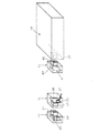
図3は本発明の第2実施形態に係る車載カメラ映像伝送システムのカメラ制御装置13及び無線受信装置17を示す模式図である。なお、図3では第1実施形態と同様の機能を有する要素については同一符号を付している。
{Second Embodiment}
<Configuration>
FIG. 3 is a schematic diagram showing the
この実施の形態の車載カメラ映像伝送システムは、図3の如く、カメラ制御装置13のコネクタ27に無線受信装置17が接続されることがあることを考慮し、無線受信装置17が収納される収納空間61をカメラ制御装置13に形成し、この収納空間61の奥部にコネクタ27を形成したものである。具体的にこの車載カメラ映像伝送システムのカメラ制御装置13では、その筐体が略直方体形状に形成されるとともに、一隅部に無線受信装置17を収納するための矩形の凹部状の収納空間61が形成されており、この収納空間61のサイズは、無線受信装置17のコネクタ45がコネクタ27に嵌合接続した際に、無線受信装置17の全体がカメラ制御装置13の略直方体形状の外寸内に収まるように設定されている。
The in-vehicle camera video transmission system of this embodiment takes into consideration that the
これにより、例えば図4に示すようにコネクタ27をカメラ制御装置13の側部等にそのまま形成して無線受信装置17を接続する場合に比べて、カメラ制御装置13と無線受信装置17を合わせた全体としてコンパクト化を図ることができる。
As a result, for example, as shown in FIG. 4, the
その他の構成は第1実施形態と同様のため、説明を省略する。 Since other configurations are the same as those of the first embodiment, description thereof is omitted.
尚、上記各実施形態では、撮像カメラ11に無線送信装置15を、カメラ制御装置13に無線受信装置17を接続したが、データ伝送を双方向にして、撮像カメラ11とカメラ制御装置13の両方に無線送受信装置を接続するようにしても差し支えない。
In each of the above embodiments, the
11 撮像カメラ
13 カメラ制御装置
15 無線送信装置
17 無線受信装置
19 伝送ケーブル
21 コネクタ
23 回路基板
25 撮像部品
27 コネクタ
31 コネクタ
33 アンテナ
35 無線回路
37 電源・グランド線
41 アンテナ
43 回路基板
45 コネクタ
51 コネクタ
53 コネクタ
61 収納空間
DESCRIPTION OF
Claims (3)
前記撮像手段と前記撮像制御手段との間に接続可能に構成されてそれらの間のデータ伝送を無線により行う第1の伝送手段と、
前記第1の伝送手段に代えて前記撮像手段と前記撮像制御手段との間に接続可能に構成されてそれらの間のデータ伝送を有線により行う第2の伝送手段と
を備えたことを特徴とする車載カメラ映像伝送システム。 In an in-vehicle camera video transmission system that performs data transmission between an imaging unit for imaging the surroundings of an automobile and an imaging control unit that receives a video signal of the imaging unit,
A first transmission unit configured to be connectable between the imaging unit and the imaging control unit and wirelessly transmitting data between them;
In place of the first transmission means, the image pickup means and the image pickup control means are configured to be connectable, and include second transmission means for performing data transmission between them by wire. In-vehicle camera video transmission system.
前記撮像手段に第1のコネクタが形成されるとともに、前記撮像制御手段に第2のコネクタが形成され、
前記第1の伝送手段が、
前記第1のコネクタに接続可能なコネクタを有する第1の無線通信部と、
前記第2のコネクタに接続可能なコネクタを有して前記第1の無線通信部と無線通信を行う第2の無線通信部と
を備え、
前記第2の伝送手段が、伝送ケーブルの一端に、前記第1のコネクタに接続可能なコネクタが形成されるとともに、他端に、前記第2のコネクタに接続可能なコネクタが形成されてなる、車載カメラ映像伝送システム。 The in-vehicle camera video transmission system according to claim 1,
A first connector is formed on the imaging means, and a second connector is formed on the imaging control means,
The first transmission means comprises:
A first wireless communication unit having a connector connectable to the first connector;
A second wireless communication unit having a connector connectable to the second connector and performing wireless communication with the first wireless communication unit;
The second transmission means is formed with a connector connectable to the first connector at one end of a transmission cable and a connector connectable to the second connector at the other end. In-vehicle camera video transmission system.
前記撮像制御手段の一部に、前記第2の無線通信部を収納するための収納空間が形成され、当該収納空間の奥部に、前記第2のコネクタが形成されたことを特徴とする車載カメラ映像伝送システム。
The in-vehicle camera video transmission system according to claim 2,
An in-vehicle system characterized in that a storage space for storing the second wireless communication unit is formed in a part of the imaging control means, and the second connector is formed at the back of the storage space. Camera video transmission system.
Priority Applications (1)
| Application Number | Priority Date | Filing Date | Title |
|---|---|---|---|
| JP2004116772A JP2005297760A (en) | 2004-04-12 | 2004-04-12 | In-vehicle camera video transmission system |
Applications Claiming Priority (1)
| Application Number | Priority Date | Filing Date | Title |
|---|---|---|---|
| JP2004116772A JP2005297760A (en) | 2004-04-12 | 2004-04-12 | In-vehicle camera video transmission system |
Publications (1)
| Publication Number | Publication Date |
|---|---|
| JP2005297760A true JP2005297760A (en) | 2005-10-27 |
Family
ID=35329831
Family Applications (1)
| Application Number | Title | Priority Date | Filing Date |
|---|---|---|---|
| JP2004116772A Pending JP2005297760A (en) | 2004-04-12 | 2004-04-12 | In-vehicle camera video transmission system |
Country Status (1)
| Country | Link |
|---|---|
| JP (1) | JP2005297760A (en) |
Cited By (1)
| Publication number | Priority date | Publication date | Assignee | Title |
|---|---|---|---|---|
| KR20140124647A (en) * | 2013-04-17 | 2014-10-27 | 주식회사 에이스테크놀로지 | Communication apparatus for vehicle |
-
2004
- 2004-04-12 JP JP2004116772A patent/JP2005297760A/en active Pending
Cited By (2)
| Publication number | Priority date | Publication date | Assignee | Title |
|---|---|---|---|---|
| KR20140124647A (en) * | 2013-04-17 | 2014-10-27 | 주식회사 에이스테크놀로지 | Communication apparatus for vehicle |
| KR102027220B1 (en) * | 2013-04-17 | 2019-10-01 | 주식회사 에이스테크놀로지 | Communication apparatus for vehicle |
Similar Documents
| Publication | Publication Date | Title |
|---|---|---|
| KR101103231B1 (en) | Connecting device to apply the function of mobile phone to vehicle | |
| JP3197668U (en) | Visual field auxiliary means for vehicles | |
| JP4119509B2 (en) | Endoscope device | |
| US8076792B2 (en) | Power line communication apparatus | |
| JP2009177785A (en) | In-vehicle wireless communication device and antenna harness | |
| JP2008207627A (en) | In-vehicle imaging system, imaging device, and display control device | |
| JP2004142500A (en) | Connector device | |
| KR20090022672A (en) | Dual camera module of one board type | |
| JP2004299511A (en) | Confirming device for rear or vehicle | |
| JP6220754B2 (en) | In-vehicle camera | |
| JP2005297760A (en) | In-vehicle camera video transmission system | |
| JP2008195282A (en) | Vehicle camera device | |
| CN114281074A (en) | Beyond-the-horizon unmanned vehicle remote control system and unmanned vehicle | |
| JP2005306266A (en) | In-vehicle wireless camera device | |
| JP7300624B2 (en) | electronic mirror camera system | |
| JP2011025850A (en) | In-vehicle broadcasting receiving system, and automobile equipped with the same | |
| JP2005297761A (en) | In-vehicle camera video transmission system | |
| KR100946160B1 (en) | Rear monitoring unit for vehicle, rear monitoring apparatus for vehicle therewith | |
| JP2005303665A (en) | Camera unit for in-vehicle camera video transmission system | |
| WO2018143308A1 (en) | Vehicle-mounted antenna device equipped with camera | |
| CN210129575U (en) | Antenna device | |
| JP4706888B2 (en) | In-vehicle image information transmission / reception device | |
| JP2004320567A (en) | Imaging device, image display system, image display method, image processing system, and image processing method | |
| JP7810635B2 (en) | Cameras, Trains, and Surveillance Systems | |
| JP2005081854A (en) | Wireless signal transmission device and transmission system |