JP2005297434A - Synthetic resin printing method and apparatus - Google Patents
Synthetic resin printing method and apparatus Download PDFInfo
- Publication number
- JP2005297434A JP2005297434A JP2004119019A JP2004119019A JP2005297434A JP 2005297434 A JP2005297434 A JP 2005297434A JP 2004119019 A JP2004119019 A JP 2004119019A JP 2004119019 A JP2004119019 A JP 2004119019A JP 2005297434 A JP2005297434 A JP 2005297434A
- Authority
- JP
- Japan
- Prior art keywords
- stage
- printing
- metal mask
- synthetic resin
- substrate
- Prior art date
- Legal status (The legal status is an assumption and is not a legal conclusion. Google has not performed a legal analysis and makes no representation as to the accuracy of the status listed.)
- Pending
Links
Images


Landscapes
- Encapsulation Of And Coatings For Semiconductor Or Solid State Devices (AREA)
- Screen Printers (AREA)
Abstract
【課題】 本発明は合成樹脂印刷装置に関し、作業者の技能の程度に影響されないで、印刷精度の向上を図ることを目的とする。
【解決手段】 ステージ140上には、集合基板21の厚さに対応した厚さの金属ブロック144,145が固定してある。ステージ140が上昇して金属ブロック144,145が印刷用メタルマスク32に接触したときにランプ222が点灯するようにした報知装置220が設けてある。ランプ222が点灯した時点でステージ140の上昇を停止させることによって、集合基板21が印刷用メタルマスク32に最適に接触した状態となる。
【選択図】 図1PROBLEM TO BE SOLVED: To improve printing accuracy without being affected by the level of skill of an operator, relating to a synthetic resin printing apparatus.
SOLUTION: On a stage 140, metal blocks 144 and 145 having a thickness corresponding to the thickness of the collective substrate 21 are fixed. A notification device 220 is provided so that the lamp 222 is turned on when the stage 140 is raised and the metal blocks 144 and 145 come into contact with the printing metal mask 32. By stopping the ascent of the stage 140 when the lamp 222 is lit, the collective substrate 21 is optimally in contact with the printing metal mask 32.
[Selection] Figure 1
Description
本発明は合成樹脂印刷方法及び装置に係り、特に、印刷用メタルマスクを使用して集合基板の上面に実装してある半導体素子を合成樹脂でもって封止するように集合基板の上面に合成樹脂を印刷する合成樹脂印刷方法及び装置に関する。 The present invention relates to a synthetic resin printing method and apparatus, and more particularly to a synthetic resin on a top surface of a collective substrate so that a semiconductor element mounted on the top surface of the collective substrate is sealed with a synthetic resin using a printing metal mask. The present invention relates to a method and apparatus for printing a synthetic resin.
図11(A)は最終製品である半導体装置10を示す。半導体装置10は、チップ状基板11上に半導体チップ12が実装してあり、且つ、半導体チップ12が印刷によって形成してある合成樹脂部13によって封止されている。この半導体装置10は、図12に示す真空合成樹脂印刷装置30を使用して製造された図11(B)に示す半導体装置集合体20を破線に沿ってスクライブして個片化したものである。
FIG. 11A shows a
従来の真空合成樹脂印刷装置30は、図12に示すように、内部に空間を有するハウジング31の内部に、印刷用メタルマスク32がその枠33をメタルマスク固定部35によって固定されて水平に支持され、メタルマスク32の下側に、半導体チップ12が複数整列して実装してある大きい集合基板21が搭載されるステージ40とこのステージ40を昇降させるステージ昇降機構50とを備え、メタルマスク32の上面側にスキージ61を左右に移動させるスキージ機構60を備え、ハウジング31の外部に、真空ポンプ70、操作パネル80、制御回路90等を備えた構成である。ステージ昇降機構50は、モータ51を有する。ステージ40の上面には、ワークである集合基板21を位置決めするための位置決めピン43が設けてある。ステージ昇降機構50は、操作パネル80のボタン操作によって動作し、停止ボタンを操作することによって停止される構成である。
As shown in FIG. 12, a conventional vacuum synthetic
モータ51が駆動されてステージ昇降機構50が動作され、ステージ40が上昇され、図13(A)に示すように集合基板21がメタルマスク32の下面に接触した状態とし、スキージ61を左右に移動させて熱硬化性の合成樹脂をメタルマスク32の開口内に刷り込むようにして落とし込んで、合成樹脂部13が全部の半導体チップ12に対して一括して印刷されて全部の半導体チップ12が一括して封止される。
The
ステージ40の最終高さH0の調整、即ち、集合基板21がメタルマスク32の下面に接触した状態の調整は、作業者が目視で行っており、専ら作業者の技能に頼っていた。
このため、ステージ40を最終高さH0に最適に位置決めする作業は時間がかかり作業性が良くなかった。
For this reason, the work for optimally positioning the
また、ステージ40を最終高さH0、即ち、集合基板21のメタルマスク32に対する位置にばらつきが出ることが避けられなかった。図13(B)に示すように、ステージ40が上記高さH0より若干下側の高さH1である場合には、密着不足となり、逆に、同図(C)に示すように、ステージ40が上記高さH0より若干上側の高さH2である場合には、集合基板21のメタルマスク32への押し付けが強過ぎることになる。この場合には、印刷の精度が低くなり、場所によっては、合成樹脂が集合基板21とメタルマスク32との間の隙間25にはみでてしまうことが起き、ステージ昇降機構50によってステージ40を下降させて、集合基板21をメタルマスク32から離した状態で、図11(B)中、符号13Aで示すように合成樹脂部が正常に形成されない場所が現れたりする。また、集合基板21のメタルマスク32への押し付けが強過ぎる場合には、メタルマスク32に作用するテンションが強くなり、メタルマスク32を傷めてその寿命が無用に短くなってしまうこともある。
Further, it is inevitable that the
そこで、本発明は、上記課題を解決した合成樹脂印刷方法及び装置を提供することを目的とする。 Then, an object of this invention is to provide the synthetic resin printing method and apparatus which solved the said subject.
そこで、上記課題を解決するため、本発明は、ステージが印刷用メタルマスクに接近するように移動してきて停止し、該印刷用メタルマスクを使用して合成樹脂を該ステージ上の被印刷物に印刷する合成樹脂印刷方法において、
上記ステージに、該被印刷物の厚さに対応した突起部を設け、
該突起部が上記印刷用メタルマスクに接触したことを検知して、該ステージの印刷時の位置を決定するようにしたことを特徴とする。
Therefore, in order to solve the above-described problems, the present invention moves and stops so that the stage approaches the printing metal mask, and uses the printing metal mask to print the synthetic resin on the printing material on the stage. In the synthetic resin printing method to
Providing a protrusion corresponding to the thickness of the substrate on the stage,
It is characterized in that the position of the stage during printing is determined by detecting that the projection has contacted the printing metal mask.
本発明によれば、ステージの最終高さに最適に位置決めする作業を、作業者の技能の巧拙に影響されずに、正確に且つ作業性良く行うことが出来る。よって、印刷を精度良く行うことが出来る。また、印刷用メタルマスクの傷みが少なく、印刷用メタルマスクの長寿命化を図ることが出来る。 According to the present invention, the operation of optimally positioning to the final height of the stage can be performed accurately and with good workability without being affected by the skill of the operator. Therefore, printing can be performed with high accuracy. Further, there is little damage to the printing metal mask, and the life of the printing metal mask can be extended.
次に本発明の実施の形態について説明する。 Next, an embodiment of the present invention will be described.
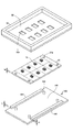
図1は本発明の実施例1になる真空合成樹脂印刷装置130を示す。真空合成樹脂印刷装置130は、ハウジング131の内部に、メタルマスク固定部135と、ステージ140と、ステージ昇降機構150と、スキージ機構160とを備え、ハウジング131の外部に、真空ポンプ170、操作パネル180、制御回路190、駆動回路200,210等を備えた構成である。
FIG. 1 shows a vacuum synthetic
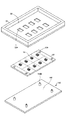
印刷用メタルマスク32は、図2に示すように、金属板であり、複数の印刷用の窓32aを有し、周囲に枠33が固定してある構成であり、枠33をメタルマスク固定部135に固定されて水平に支持してある。
As shown in FIG. 2, the
スキージ機構160はメタルマスク32の上面側に配置してあり、スキージ161をメタルマスク32の上面に押し当てつつ左右に移動させる。
The
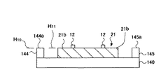
ステージ140はメタルマスク32の下側に配置される。ステージ140は図2に示すように、金属板であり、上面の中央に、集合基板搭載部142を有し、この集合基板搭載部142に集合基板位置決めピン143が固定してあり、集合基板搭載部142の両側に沿って突起部としての金属製で断面が四角で細長い形状の金属ブロック144,145が固定してある。金属ブロック144,145の厚さt1は集合基板21の厚さt0と等しいかこれより若干厚く定めてある。よって、図3に示すように、半導体チップ12が複数整列して実装してある集合基板21がその穴21aを位置決めピン143に嵌合させて集合基板搭載部142に搭載された状態において、金属ブロック144,145の上面144a,145aの高さH10は、集合基板21の上面21bの高さH11と同じ高さ或いはこれよりも0.1mm程度高い高さに位置している。
The
ステージ昇降機構150は、モータ151によって駆動されて、ステージ140を昇降させる。
The
真空合成樹脂印刷装置130には、上昇するステージ140が最適高さに到ったことを知らせる報知装置220が設けてある。報知装置220は、電源221及びランプ222が直列に接続してあり、電源221から延びている電線223の端がステージ140に接続してあり、ランプ222から延びている電線224の端がメタルマスク32に接続してある電気回路である。ランプ222は操作パネル180に設けてある。ステージ140とメタルマスク32とが上記の電気回路中のスイッチとして機能する。
The vacuum synthetic
集合基板21に合成樹脂の印刷を行うには、先ず、低い位置に位置しているステージ140に集合基板21を搭載し、真空ポンプ170を駆動させてハウジング131の内部の空気を排気し、操作パネル180のボタンを操作してモータ151を駆動させてステージ昇降機構150を動作させ、ステージ140を図13(A)に示す状態にまで上昇させる。ステージ140が図13(A)に示す位置に近づくとステージ上昇速度は低速となる。
In order to print the synthetic resin on the
ステージ140が低い位置に位置している間は、報知装置220の電気回路は開いており、ランプ222は消灯状態である。ステージ140が上昇して、金属ブロック144,145がメタルマスク32に接触すると、報知装置220の電気回路が閉じ、ランプ222が点灯する。ランプ222が点灯したときに、作業者は、停止ボタンを操作する。これによって、モータ151が停止しステージ昇降機構150が動作を停止し、ステージ140はそのときの位置に停止し、図13(A)に示すように集合基板21がメタルマスク32の下面に最適に接触した状態となる。即ち、ステージ140の高さは、ランプ222が点灯したことに基づいて決定される。
While the
続いて、スキージ機構160を動作させスキージ161をメタルマスク32の上面に押し当てつつ左右に移動させる。合成樹脂がメタルマスク32の開口内に刷り込むようにして落とし込まれ、合成樹脂部13が全部の半導体チップ12に対して一括して印刷されて全部の半導体チップ12が一括して封止される。
Subsequently, the
ここで、ステージ140を最適位置に停止させるには、作業者はランプ222が点灯したことを確認して停止ボタンを操作するだけでよいため、作業がし易く、時間もかからず、作業性が良い。しかも、作業者の技能の程度に影響されないで、ステージ140を最適位置に停止させることが可能である。
Here, in order to stop the
更には、ステージ140の停止高さ位置のばらつきが少なく、図13(B)、(C)に示す状態が起きにくく、合成樹脂の印刷精度は高くなり、また、メタルマスク32の寿命が無用に短くなってしまうことも起きない。
Furthermore, the variation in the stop height position of the
上記の金属ブロック144,145をメタルマスク32の下面に設けて、上昇してきたステージ140が金属ブロック144,145に接触するようにしてもよい。
The metal blocks 144 and 145 may be provided on the lower surface of the
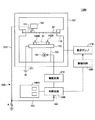
図4は本発明の実施例2になる真空合成樹脂印刷装置130Aを示す。図4中,図1に示す構成部分と同じ部分には同じ符号を付す。真空合成樹脂印刷装置130Aは、図1中の報知装置220に代えて、上昇するステージ140が最適高さに到ったことを検知する検知回路230が設けてあり、この検知回路230からの検知信号が制御回路190Aに供給されて、制御回路190Aが駆動回路210の動作を自動的に停止させる構成である。
FIG. 4 shows a vacuum synthetic
検知回路230は、ステージ140に接続してある電源231と、メタルマスク32と接続してあり他端が抵抗Rを介して接地してある電線232と、抵抗Rの端から引き出されて制御回路190Aの入力ポート191に接続してある電線233とよりなる構成である。ステージ140上の金属ブロック144,145とメタルマスク32とがスイッチとして機能する。
The
操作パネル180Aのボタンを操作すると、制御回路190Aによって駆動回路210が動作され、モータ151が駆動されてステージ昇降機構150が動作され、ステージ140が上昇する。ステージ140が低い位置に位置している間は、上記スイッチは開状態にあり、入力ポート191の電位はLであり、制御回路190Aは駆動回路210を動作状態に保つ。
When the button on the
ステージ140が上昇して、金属ブロック144,145がメタルマスク32に接触すると、検知回路230のスイッチが閉じ、入力ポート191の電位がHとなり、制御回路190Aは駆動回路210の動作を停止させる。これによって、モータ151が停止しステージ昇降機構150が動作を停止し、ステージ140はそのときの位置に停止し、図13(A)に示すように集合基板21がメタルマスク32の下面に最適に接触した状態となる。即ち、ステージ140の高さは、検知回路230の検知動作に基づいて決定される。
When the
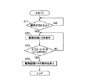
制御回路190Aはマイクロコンピュータで構成してあり、図5に示すように動作する。即ち、操作パネルが操作されたと判断すると、駆動回路210を動作させる(ST1,ST2)。入力ポート191の電位がHではないと判断している間は、駆動回路210を動作させ続け、入力ポート191の電位がHであると判断すると、駆動回路210の動作を停止させる(ST3,ST4)。
The
真空合成樹脂印刷装置130Aによれば、作業者の技能の程度に影響されないで、ステージ140を最適位置に停止させることが可能であり、更には、ステージ140の停止高さ位置のばらつきが少なく、図13(B)、(C)に示す状態が起きにくく、合成樹脂の印刷精度は高くなり、また、メタルマスク32の寿命が無用に短くなってしまうことも起きない。
According to the vacuum synthetic
上記の金属ブロック144,145をメタルマスク32の下面に設けて、上昇してきたステージ140が金属ブロック144,145に接触するようにしてもよい。
The metal blocks 144 and 145 may be provided on the lower surface of the
図6は本発明の実施例3になる真空合成樹脂印刷装置130Bを示す。図6中,図4に示す構成部分と同じ部分には同じ符号を付す。真空合成樹脂印刷装置130Bは、図4に示す真空合成樹脂印刷装置130Aと比較して、ステージ140上の構造が相違している。
FIG. 6 shows a vacuum synthetic
図7に示すように、ステージ140上は、金属ブロック144,145を除去し、位置決めピン143に代えて、位置決めピン143Bを備えた構造である。
As shown in FIG. 7, the
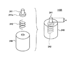
位置決めピン143Bは、図8に示すように、位置決めピン本体240と、ピン241と、圧縮コイルばね242とを組み合わせてなる構造である。位置決めピン本体240は、筒形状であり、図2中の位置決めピン143と同じ径及び高さ寸法を有する。ピン241は、下部にフランジ部241aを有し、位置決めピン本体240の内部に設けてあり、圧縮コイルばね242によって押し上げられて、位置決めピン本体240から上方に突き出している。ピン241は、圧縮コイルばね242を圧縮させて位置決めピン本体240の内部に完全に沈み込むことが可能である。ピン241はそのフランジ部241aが位置決めピン本体240の天板部に当る位置まで押し上げられており、ピン241の位置決めピン本体240の上面から上方に突き出している寸法aは精度良く定まっている。
As shown in FIG. 8, the
ステージ140上の位置決めピン143Bとメタルマスク32とがスイッチとして機能する。制御回路190Bは、検知回路230からの検知信号が制御回路190Bに供給されてから所定時間T1経過した時点で、駆動回路210の動作を自動的に停止させるように動作する。この所定時間T1は、ピン241が位置決めピン本体240から上方に突き出している寸法aとステージ昇降機構150によってステージ140が上昇される最終段階の速度とによって決定され、ステージ140が距離aだけ上昇するに要する時間である。
The positioning pins 143B on the
次に、真空合成樹脂印刷装置130Bの動作について説明する。
Next, the operation of the vacuum synthetic
図9(A)は、集合基板21がその穴21aを位置決めピン143Bに嵌合させてステージ140上に搭載された状態を示す。ピン241は集合基板21よりも上方に突き出している。操作パネル180Bのボタンを操作すると、制御回路190Bによって駆動回路210が動作され、モータ151が駆動されてステージ昇降機構150が動作され、ステージ140が上昇する。ステージ140が低い位置に位置している間は、上記スイッチは開状態にあり、入力ポート191の電位はLであり、制御回路190Bは駆動回路210を動作状態に保つ。
FIG. 9A shows a state in which the
ステージ140が上昇して、図9(B)に示すように、ピン241がメタルマスク32に接触すると、検知回路230のスイッチが閉じ、入力ポート191の電位がHとなり、制御回路190Bはカウントを開始し、駆動回路210は動作を継続し、ステージ昇降機構150は動作し続けてステージ140は低速度で上昇し続ける。このとき、メタルマスク32に当っているピン241は、圧縮コイルばね242を撓ませつつ位置決めピン本体240内に相対的に押し込まれる。
When the
制御回路190Bは、上記のカウントを開始してから所定時間T1経過した時点で、駆動回路210の動作を停止させる。これによって、モータ151が停止しステージ昇降機構150が動作を停止し、ステージ140はそのときの位置に停止し、図9(C)及び図13(A)に示すように集合基板21がメタルマスク32の下面に最適に接触した状態となる。即ち、ステージ140の高さは、検知回路230の検知動作を基準に決定される。
The
制御回路190Bはマイクロコンピュータで構成してあり、図10に示すように動作する。即ち、操作パネルが操作されたと判断すると、駆動回路210を動作させる(ST11,ST12)。入力ポート191の電位がHではないと判断している間は、駆動回路210を動作させ続け、入力ポート191の電位がHであると判断すると、タイマを起動させる(ST14)。時間T1経過してタイムアウトとなると、駆動回路210の動作を停止させる(ST15,ST16)。
The
真空合成樹脂印刷装置130Bによれば、作業者の技能の程度に影響されないで、ステージ140を最適位置に停止させることが可能であり、更には、ステージ140の停止高さ位置のばらつきが少なく、図13(B)、(C)に示す状態が起きにくく、合成樹脂の印刷精度は高くなり、また、メタルマスク32の寿命が無用に短くなってしまうことも起きない。
According to the vacuum synthetic
位置決めピン143Bは、集合基板21の搭載位置を決定する役割とステージ140を最適位置に停止させる役割とを兼ね備えている。よって、ステージ140上には、位置決めピン143B以外に、ステージ140を最適位置に停止させるための他の部品を設ける必要はない。
The positioning pins 143B have both the role of determining the mounting position of the
32 印刷用メタルマスク
130、130A,130B 真空合成樹脂印刷装置
131 ハウジング
135 メタルマスク固定部
140 ステージ
143B 集合基板位置決めピン
144,145 金属ブロック
150 ステージ昇降機構
160 スキージ機構
170 真空ポンプ
190,190A,190B 制御回路
220 報知装置
222 ランプ
230 検知回路
240 位置決めピン本体
241 ピン
242 圧縮コイルばね
32 Metal mask for printing 130, 130A, 130B Vacuum
Claims (4)
上記ステージ又は印刷用メタルマスクに、該被印刷物の厚さに対応した突起部を設け、
該突起部が上記印刷用メタルマスク又はステージに接触したことを検知して、該ステージの印刷時の位置を決定するようにしたことを特徴とする合成樹脂印刷方法。 In the synthetic resin printing method in which the stage moves so as to approach the printing metal mask and stops, and the synthetic resin is printed on the printed material on the stage using the printing metal mask,
Providing a projection corresponding to the thickness of the substrate on the stage or printing metal mask,
A synthetic resin printing method, wherein the projection is detected by contacting the metal mask for printing or the stage, and the position of the stage during printing is determined.
上記ステージ又は印刷用メタルマスクに該被印刷物の厚さに対応した突起部を設けると共に、
該突起部が上記印刷用メタルマスク又はステージに接触したことを報知する報知手段を備えてなり、
該報知手段による報知によって、該ステージの印刷時の位置が決定されるようにしたことを特徴とする合成樹脂印刷装置。 In the synthetic resin printing apparatus for moving the stage so as to approach the printing metal mask and stopping, and printing the synthetic resin on the substrate on the stage using the printing metal mask,
Providing a projection corresponding to the thickness of the substrate on the stage or printing metal mask,
Comprising notifying means for notifying that the protruding portion has contacted the printing metal mask or stage;
A synthetic resin printing apparatus characterized in that a position at the time of printing of the stage is determined by notification by the notification means.
上記ステージ又は印刷用メタルマスクに該被印刷物の厚さに対応した突起部を設けると共に、
該突起部が上記印刷用メタルマスク又はステージに接触したことを検知する検知手段と、
該検知手段の検知動作に応じて、上記ステージ移動手段の動作を停止させる制御手段と
を備えた構成としたことを特徴とする合成樹脂印刷装置。 In the synthetic resin printing apparatus for moving the stage so as to approach the printing metal mask by the stage moving means and stopping, and printing the synthetic resin on the printing material on the stage using the printing metal mask,
Providing a projection corresponding to the thickness of the substrate on the stage or printing metal mask,
Detecting means for detecting that the protrusion has contacted the printing metal mask or stage;
A synthetic resin printing apparatus comprising: a control unit that stops the operation of the stage moving unit according to a detection operation of the detection unit.
上記ステージに、該被印刷物の位置を決めると共に該被印刷物よりも所定寸法突き出しており、沈み可能である構造の被印刷物位置決め用ピンを設けると共に、
該被印刷物位置決め用ピンが上記印刷用メタルマスクに接触したことを検知する検知手段と、
該検知手段が検知動作してから所定の時間経過した時点で上記ステージ移動手段の動作を停止させる制御手段と
を備えた構成としたことを特徴とする合成樹脂印刷装置。 In the synthetic resin printing apparatus for moving the stage so as to approach the printing metal mask by the stage moving means and stopping, and printing the synthetic resin on the printing material on the stage using the printing metal mask,
In the stage, the position of the printed material is determined and a predetermined dimension protrudes from the printed material and is provided with a printed material positioning pin having a structure that can sink,
Detecting means for detecting that the printing object positioning pin is in contact with the printing metal mask;
A synthetic resin printing apparatus comprising: a control unit configured to stop the operation of the stage moving unit when a predetermined time has elapsed after the detection unit performs the detection operation.
Priority Applications (1)
| Application Number | Priority Date | Filing Date | Title |
|---|---|---|---|
| JP2004119019A JP2005297434A (en) | 2004-04-14 | 2004-04-14 | Synthetic resin printing method and apparatus |
Applications Claiming Priority (1)
| Application Number | Priority Date | Filing Date | Title |
|---|---|---|---|
| JP2004119019A JP2005297434A (en) | 2004-04-14 | 2004-04-14 | Synthetic resin printing method and apparatus |
Publications (1)
| Publication Number | Publication Date |
|---|---|
| JP2005297434A true JP2005297434A (en) | 2005-10-27 |
Family
ID=35329561
Family Applications (1)
| Application Number | Title | Priority Date | Filing Date |
|---|---|---|---|
| JP2004119019A Pending JP2005297434A (en) | 2004-04-14 | 2004-04-14 | Synthetic resin printing method and apparatus |
Country Status (1)
| Country | Link |
|---|---|
| JP (1) | JP2005297434A (en) |
Cited By (3)
| Publication number | Priority date | Publication date | Assignee | Title |
|---|---|---|---|---|
| JP2007245435A (en) * | 2006-03-15 | 2007-09-27 | Fuji Mach Mfg Co Ltd | Screen printing method and screen printing apparatus |
| JP2009038177A (en) * | 2007-08-01 | 2009-02-19 | Sanyu Rec Co Ltd | Resin sealing method and resin sealing device |
| WO2019138569A1 (en) * | 2018-01-15 | 2019-07-18 | 株式会社Fuji | Backup block and screen-printing machine |
-
2004
- 2004-04-14 JP JP2004119019A patent/JP2005297434A/en active Pending
Cited By (6)
| Publication number | Priority date | Publication date | Assignee | Title |
|---|---|---|---|---|
| JP2007245435A (en) * | 2006-03-15 | 2007-09-27 | Fuji Mach Mfg Co Ltd | Screen printing method and screen printing apparatus |
| JP2009038177A (en) * | 2007-08-01 | 2009-02-19 | Sanyu Rec Co Ltd | Resin sealing method and resin sealing device |
| WO2019138569A1 (en) * | 2018-01-15 | 2019-07-18 | 株式会社Fuji | Backup block and screen-printing machine |
| JPWO2019138569A1 (en) * | 2018-01-15 | 2020-12-17 | 株式会社Fuji | Backup block and screen printing machine |
| JP7015325B2 (en) | 2018-01-15 | 2022-02-02 | 株式会社Fuji | Backup block and screen printer |
| US11369025B2 (en) | 2018-01-15 | 2022-06-21 | Fuji Corporation | Backup block and screen-printing machine |
Similar Documents
| Publication | Publication Date | Title |
|---|---|---|
| KR920007959B1 (en) | Electromagnetic Base Attachment Drill Unit | |
| CN112616002B (en) | Camera module and electronic equipment | |
| JP2005297434A (en) | Synthetic resin printing method and apparatus | |
| JPH09288956A (en) | Contact unit slide of contactor | |
| JP2000146624A5 (en) | ||
| CN216846624U (en) | Temperature monitoring mechanism in oven | |
| CN114103407B (en) | CCD accurate alignment screen printer | |
| US20090128140A1 (en) | Vehicle switch | |
| JP2009178882A (en) | Screen printing device, operation control method and program | |
| CN1482642A (en) | High frequency relay | |
| CN215727779U (en) | Dustproof construction of section analysis appearance | |
| CN213681168U (en) | Mounting assembly for lighting fixture and press-buckle block | |
| CN209833493U (en) | Backlight structure of reading lamp switch | |
| CN212341386U (en) | Detection device | |
| CN103021696B (en) | Automatic change-over switching device | |
| CN222381028U (en) | Wire pulling and arranging device | |
| JPH10120326A (en) | Elevator brake system | |
| CN112796254B (en) | Anti-collision structure of parking lifting column | |
| CN219683126U (en) | Frictioning mechanism and viscose feeding system | |
| CN210598335U (en) | Intelligence stereo garage lift pine chain detection device and intelligent stereo garage | |
| CN220438467U (en) | Electronic equipment screen lighting function test fixture | |
| CN216960128U (en) | Installation solidification equipment of earphone charging spring sheet | |
| CN218333726U (en) | Wafer loading device and photoetching machine | |
| CN220106295U (en) | Mounting device of mounting plate assembly of dual-power change-over switch | |
| CN220548183U (en) | Mobile phone cover plate adsorption carrier |