JP2005297330A - Valve body, valve device, liquid ejecting apparatus, and cleaning method for liquid ejecting apparatus - Google Patents
Valve body, valve device, liquid ejecting apparatus, and cleaning method for liquid ejecting apparatus Download PDFInfo
- Publication number
- JP2005297330A JP2005297330A JP2004115973A JP2004115973A JP2005297330A JP 2005297330 A JP2005297330 A JP 2005297330A JP 2004115973 A JP2004115973 A JP 2004115973A JP 2004115973 A JP2004115973 A JP 2004115973A JP 2005297330 A JP2005297330 A JP 2005297330A
- Authority
- JP
- Japan
- Prior art keywords
- valve
- valve device
- liquid
- ink
- fluid
- Prior art date
- Legal status (The legal status is an assumption and is not a legal conclusion. Google has not performed a legal analysis and makes no representation as to the accuracy of the status listed.)
- Pending
Links
- 239000007788 liquid Substances 0.000 title claims abstract description 89
- 238000004140 cleaning Methods 0.000 title claims description 15
- 238000000034 method Methods 0.000 title claims description 8
- 238000004891 communication Methods 0.000 claims abstract description 39
- 239000012530 fluid Substances 0.000 claims description 43
- 239000000463 material Substances 0.000 claims description 26
- 238000003860 storage Methods 0.000 claims description 15
- 239000007921 spray Substances 0.000 claims 1
- 238000007789 sealing Methods 0.000 abstract description 28
- 238000004519 manufacturing process Methods 0.000 description 10
- 230000008859 change Effects 0.000 description 4
- 239000002699 waste material Substances 0.000 description 4
- 210000000078 claw Anatomy 0.000 description 2
- 238000010586 diagram Methods 0.000 description 2
- 238000001035 drying Methods 0.000 description 2
- 230000000694 effects Effects 0.000 description 2
- 230000007246 mechanism Effects 0.000 description 2
- 230000004044 response Effects 0.000 description 2
- 239000002904 solvent Substances 0.000 description 2
- 230000002463 transducing effect Effects 0.000 description 2
- 238000000018 DNA microarray Methods 0.000 description 1
- 230000004308 accommodation Effects 0.000 description 1
- 230000002411 adverse Effects 0.000 description 1
- 230000004888 barrier function Effects 0.000 description 1
- 230000015572 biosynthetic process Effects 0.000 description 1
- 230000000903 blocking effect Effects 0.000 description 1
- 239000006103 coloring component Substances 0.000 description 1
- 238000009795 derivation Methods 0.000 description 1
- 239000007772 electrode material Substances 0.000 description 1
- 230000009969 flowable effect Effects 0.000 description 1
- 238000002347 injection Methods 0.000 description 1
- 239000007924 injection Substances 0.000 description 1
- 239000004973 liquid crystal related substance Substances 0.000 description 1
- 230000000149 penetrating effect Effects 0.000 description 1
- 230000009467 reduction Effects 0.000 description 1
- 230000002040 relaxant effect Effects 0.000 description 1
- 239000011347 resin Substances 0.000 description 1
- 229920005989 resin Polymers 0.000 description 1
- 238000007711 solidification Methods 0.000 description 1
- 230000008023 solidification Effects 0.000 description 1
Images


Landscapes
- Ink Jet (AREA)
Abstract
【課題】 小型化を実現することができる弁体、弁装置及び液体噴射装置を提供する。
【解決手段】 プリンタは、加圧ポンプを停止させて第1及び第2のインクカートリッジのインクの供給を停止し、第1及び第2の弁装置を非連通状態とする。次に、キャップ部材によって各ノズルを封止した後に、吸引ポンプを駆動させて、同ノズルに負圧をかける。この負圧は自己封止弁を介して、各バルブ室31の第2の流路36にまで到達する。そしてプリンタは、記録ヘッド、自己封止弁及び第2の流路36に至るまでに負圧が蓄積されると、インクの供給を再開する。第1及び第2の弁装置の各バルブ室31に導入されたインクは、第2の流路36にまで到達した負圧によって吸引されて自己封止弁を介して記録ヘッドに向けて一気に流動する。これによって、自己封止弁内又は記録ヘッド内に侵入した気泡は、このインクの流動に伴ってノズルからキャップ部材に排出される。
【選択図】 図4PROBLEM TO BE SOLVED: To provide a valve body, a valve device, and a liquid ejecting apparatus that can be miniaturized.
The printer stops the pressurizing pump to stop the supply of ink from the first and second ink cartridges, and brings the first and second valve devices into a non-communication state. Next, after each nozzle is sealed with the cap member, the suction pump is driven to apply a negative pressure to the nozzle. This negative pressure reaches the second flow path 36 of each valve chamber 31 via the self-sealing valve. When the negative pressure is accumulated until the printer reaches the recording head, the self-sealing valve, and the second flow path 36, the printer resumes the ink supply. The ink introduced into the valve chambers 31 of the first and second valve devices is sucked by the negative pressure reaching the second flow path 36 and flows all at once toward the recording head via the self-sealing valve. To do. As a result, bubbles that have entered the self-sealing valve or the recording head are discharged from the nozzle to the cap member as the ink flows.
[Selection] Figure 4
Description
本発明は、弁体、弁装置、液体噴射装置及び液体噴射装置のクリーニング方法に関する。 The present invention relates to a valve body, a valve device, a liquid ejecting apparatus, and a cleaning method for the liquid ejecting apparatus.
従来、液体噴射装置としてインクジェット式記録装置が広く知られている。このインクジェット式記録装置では、インク収容体から供給されるインクを、キャリッジに設けられた記録ヘッドのノズルからインク滴として吐出する。そして、このキャリッジを移動させながら記録媒体に向けてインク滴を吐出しドットを形成することによって記録を行うようになっていた。 Conventionally, an ink jet recording apparatus is widely known as a liquid ejecting apparatus. In this ink jet recording apparatus, ink supplied from an ink container is ejected as ink droplets from nozzles of a recording head provided on a carriage. Then, recording is performed by ejecting ink droplets toward the recording medium while moving the carriage to form dots.
このようなインクジェット式記録装置の中には、インク収容体から記録ヘッドに供給されるインクが、同インク供給体側に逆流することを抑制するために逆止弁を設けたものがある。(例えば、特許文献1。)。 Some ink jet recording apparatuses are provided with a check valve in order to prevent the ink supplied from the ink container to the recording head from flowing back to the ink supply side. (For example, Patent Document 1).
特許文献1に記載のインクジェット式記録装置では、キャリッジにインク供給ポンプが備えられていた。このインク供給ポンプは、インク収容体からインクを受けて記録ヘッドに供給する。このインク供給ポンプの本体ケース内には、移動部材が、同本体ケース内を摺動可能となるように嵌挿されていて、同移動部材には、逆止弁が設けられている。この逆止弁は、本体ケースのインク導入口から導入されるインクが、同本体ケースのインク導出口に向けて流動するときのみに開状態となってその流動を許容し、反対にインク導出口からインク導入口に流動(逆流)するときには閉状態となってその逆流を抑制するようになっていた。 In the ink jet recording apparatus described in Patent Document 1, the carriage is provided with an ink supply pump. The ink supply pump receives ink from the ink container and supplies it to the recording head. A moving member is fitted in the main body case of the ink supply pump so as to be slidable in the main body case, and a check valve is provided on the moving member. This check valve is opened only when the ink introduced from the ink introduction port of the main body case flows toward the ink outlet port of the main body case, and allows the flow. When the fluid flows from the ink to the ink inlet (reverse flow), it is in a closed state to suppress the reverse flow.
さらに、インク供給ポンプでは、この移動部材を、本体ケース内にてインク導入口側からインク導出側に向けて摺動させることにより、同インク導入口側に負圧を発生させて、インク収容体からインクを吸引して同本体ケース内に導入するようになっている。そして、記録媒体の記録の際に移動するキャリッジの振動に伴って、同移動体を本体ケース内にて摺動させることでインクを吸引し記録ヘッドに供給するようになっていた。
ところで、一般に、インクジェット式記録装置に用いられるインクは、揮発性を有するインク溶媒に着色成分を溶かすことによって構成されている。従って、ノズルから記録ヘッド内に気泡が浸入すると、同記録ヘッド内にてインク溶媒が蒸発し、インクが増粘してしまうことがあった。これは、ノズルの目詰まりを引き起こし、ドット抜け等の記録ヘッドの吐出不良を引き起こす原因となっていた。このため、記録ヘッドに浸入した気泡を排出させる必要があった。 By the way, in general, ink used in an ink jet recording apparatus is configured by dissolving a coloring component in a volatile ink solvent. Therefore, when bubbles enter the recording head from the nozzle, the ink solvent evaporates in the recording head, and the ink may thicken. This causes clogging of the nozzles and causes a discharge failure of the recording head such as missing dots. For this reason, it is necessary to discharge bubbles that have entered the recording head.
そして、このような問題を解決する方法として、ノズル側から負圧をかけることで、強制的に同ノズルからインクを排出させるいわゆるクリーニングが提案されている。このクリーニングでは、インク収容体からのインクの供給を電磁ソレノイドバルブ等のバルブ装置にて遮断するとともに、記録ヘッドのノズル側から負圧をかける。そして、ノズルにかかる負圧が蓄積された時点で、バルブ装置による遮断を解除することで、ノズルから気泡とともに増粘したインクを一気に吐出させ排出ていた。 As a method for solving such a problem, so-called cleaning in which ink is forcibly discharged from the nozzle by applying a negative pressure from the nozzle side has been proposed. In this cleaning, ink supply from the ink container is shut off by a valve device such as an electromagnetic solenoid valve, and negative pressure is applied from the nozzle side of the recording head. Then, when the negative pressure applied to the nozzle is accumulated, the blocking by the valve device is released, so that the ink thickened with bubbles from the nozzle is ejected at once and discharged.
しかしながら、特許文献1に記載のインクジェット式記録装置のように、インク供給ポンプを備えているものに、さらに電磁ソレノイドバルブ等のバルブ弁装置を備えることは、駆動電源等の部品点数が増加し同インクジェット式記録装置が大型化する虞があった。これは、近年要望されているインクジェット式記録装置の小型化への弊害となっていた。 However, the provision of a valve valve device such as an electromagnetic solenoid valve in addition to an ink supply pump as in the ink jet recording apparatus described in Patent Document 1 increases the number of components such as a drive power source and the like. There is a possibility that the ink jet recording apparatus is increased in size. This has been an adverse effect on the downsizing of the ink jet recording apparatus that has been requested in recent years.
本発明は、上記問題点を解消するためになされたものであって、小型化を実現することができる弁体、弁装置及び液体噴射装置を提供することにある。 The present invention has been made to solve the above-described problems, and it is an object of the present invention to provide a valve body, a valve device, and a liquid ejecting apparatus that can realize downsizing.
本発明の弁体は、本体ケースに形成した凹部をフィルム材にて被覆して流体を収容する流体収容室と、前記流体収容室に流体を導入する導入部と、前記流体収容室から流体を導出する導出部と、前記導入部及び前記導出部に形成した流路の少なくとも一方を開閉することで、同導入部と同導出部との間の流体の流量を調整する開閉手段とを備え、前記フィルム材を介して前記開閉手段を付勢して、前記流路の少なくとも一方を閉路するとともに、前記導入部から前記流体収容室内に導入された流体の圧力が、前記フィルム材に付与されると、同付勢を緩和し、前記流路を開路する付勢手段を備えた。 The valve body of the present invention includes a fluid storage chamber that covers a recess formed in a main body case with a film material to store a fluid, an introduction portion that introduces fluid into the fluid storage chamber, and fluid from the fluid storage chamber. A deriving section for deriving, and an opening / closing means for adjusting the flow rate of the fluid between the introducing section and the deriving section by opening and closing at least one of the flow paths formed in the introducing section and the deriving section, The opening / closing means is urged through the film material to close at least one of the flow paths, and the pressure of the fluid introduced from the introduction portion into the fluid storage chamber is applied to the film material. And an urging means for relaxing the urging force and opening the flow path.
これによれば、弁体は、導入部から流体を導入することによって連通状態となる。また、反対に、この流体の導入を停止することによって、非連通状態となる。即ち、弁体の連通状態及び非連通状態は、この流体の導入によって制御することができる。これによって、弁体は、電磁ソレノイドバルブ等のように駆動電源等を必要としない。この結果、部品点数を低減し小型化を実現することができる。さらに、弁体の製造コストを低減することができる。 According to this, a valve body will be in a communication state by introduce | transducing a fluid from an introducing | transducing part. On the other hand, when the introduction of the fluid is stopped, a non-communication state is established. That is, the communication state and non-communication state of the valve body can be controlled by introducing the fluid. As a result, the valve element does not require a driving power source or the like unlike an electromagnetic solenoid valve. As a result, the number of parts can be reduced and downsizing can be realized. Furthermore, the manufacturing cost of the valve body can be reduced.
本発明の弁装置は、本体ケースの凹部をフィルム材にて被覆して流体を収容する流体収容室と、前記流体収容室に流体を導入する導入部と、前記流体収容室から流体を導出する導出部と、前記導入部及び前記導出部に形成した流路の少なくとも一方を開閉することで、同導入部と同導出部との間の流体の流量を調整する開閉手段と、前記フィルム材を介して前記開閉手段を付勢して、前記流路の少なくとも一方を閉路させる付勢手段とを備えた弁体を、少なくとも2つ以上重ね合わせることによって形成される弁装置であって、前記本体ケースは、前記弁体を重ね合わせた際に、隣接する弁体の付勢手段を支持する。 The valve device according to the present invention includes a fluid storage chamber in which a concave portion of a main body case is covered with a film material to store a fluid, an introduction portion for introducing a fluid into the fluid storage chamber, and a fluid is led out from the fluid storage chamber. An opening / closing means for adjusting a flow rate of fluid between the introduction portion and the lead-out portion by opening / closing at least one of the lead-out portion, the introduction portion, and the flow path formed in the lead-out portion; and the film material. A valve device formed by superimposing at least two valve bodies provided with biasing means for biasing the opening and closing means via the biasing means for closing at least one of the flow paths, The case supports the urging means of the adjacent valve body when the valve bodies are overlapped.
これによれば、弁体は、弁装置を形成した際に、隣接する弁体の付勢手段を支持することができる。これによって、付勢手段を支持するために部品を新たに設ける必要がないので、形成される弁装置の部品点数を低減することができる。この結果、弁装置の小型化及び製造コストの低減を実現することができる。また、この弁装置は、弁体を2つ以上重ねあわせることで形成される。このように、弁装置を、同様に構成された弁体から形成することによって、弁装置の製造コストを低減することができる。 According to this, the valve body can support the biasing means of the adjacent valve body when the valve device is formed. Thereby, since it is not necessary to newly provide parts to support the urging means, it is possible to reduce the number of parts of the formed valve device. As a result, it is possible to reduce the size of the valve device and reduce the manufacturing cost. The valve device is formed by stacking two or more valve bodies. Thus, the manufacturing cost of a valve apparatus can be reduced by forming a valve apparatus from the valve body similarly comprised.
この弁装置の前記付勢手段は、バネ部材であって、前記本体ケースには、同バネ部材を支持するバネ座が形成されている。
これによれば、バネ部材は、隣接する弁体の本体ケースに形成されたバネ座によって支持される。これによって、弁装置を形成する各弁体は、それぞれ隣接する弁体の本体ケースにバネ部材を支持させて、フィルム材を介して開閉手段を付勢し流体の流量を調整することができる。
The biasing means of the valve device is a spring member, and a spring seat for supporting the spring member is formed in the main body case.
According to this, a spring member is supported by the spring seat formed in the main body case of the adjacent valve body. Accordingly, each valve body forming the valve device can adjust the flow rate of the fluid by supporting the spring member on the body case of the adjacent valve body and urging the opening / closing means via the film material.
この弁装置の前記開閉手段は、前記フィルム材に固着された可撓性を有するシール部材であって、同シール部材は、前記導入部及び前記導出部に形成した前記流路の少なくとも一方を開閉して、前記流体の流量を調整する。 The opening / closing means of the valve device is a flexible sealing member fixed to the film material, and the sealing member opens and closes at least one of the flow paths formed in the introduction portion and the outlet portion. Then, the flow rate of the fluid is adjusted.
これによれば、シール部材は、フィルム材を介して付勢手段によって付勢されて、導入部及び導出部に形成した流路の少なくとも一方を開閉することができる。このシール部材は、可撓性を有するので、例えば導入部又は導出部により当接し流路を封止することができる。この結果、シール部材は、より安易に流路を閉路することができる。 According to this, the sealing member is urged by the urging means via the film material, and can open and close at least one of the flow paths formed in the introduction part and the outlet part. Since this seal member has flexibility, it can be in contact with, for example, the introduction portion or the lead-out portion to seal the flow path. As a result, the seal member can close the flow path more easily.
この弁装置の前記フィルム材の表又は裏の少なくとも一方には、前記バネ部材を受け止める受圧板を設けた。
これによれば、このフィルム材には、受圧板を介してバネ部材からの付勢力がより付与される。これによって、フィルム材に固着されたシール部材は、より安易に流路を閉路することができる。この結果、シール部材は、より流体の流量を調整することができる。
A pressure receiving plate for receiving the spring member was provided on at least one of the front and back of the film material of the valve device.
According to this, a biasing force from the spring member is further applied to the film material via the pressure receiving plate. Thereby, the sealing member fixed to the film material can more easily close the flow path. As a result, the seal member can adjust the flow rate of the fluid more.
この弁装置の前記バネ部材は、コイルバネであって、前記本体ケースには、隣接する前記弁体の本体ケースとの間に前記コイルバネを取着するための間隔を保持する間隔保持手段を設けた。 The spring member of the valve device is a coil spring, and the main body case is provided with interval holding means for holding an interval for attaching the coil spring between the main body cases of the adjacent valve bodies. .
これによれば、コイルバネは、各弁体の本体ケース間に形成される間隔に取着される。そして、本体ケースのバネ座に支持されながら、フィルム材を介して、開閉手段を付勢することができる。 According to this, a coil spring is attached to the space | interval formed between the main body cases of each valve body. The opening / closing means can be biased through the film material while being supported by the spring seat of the main body case.
この弁装置は、前記弁体を重ね合わせる際に、各弁体の位置決めをする位置決め手段を設けた。
これによれば、弁装置を形成するときには、各弁体はこの位置決め手段によって位置決めされるので、容易に重ね合わせることができる。この結果、前記弁装置を形成する際の作業性を向上させることができる。
This valve device is provided with positioning means for positioning each valve body when the valve bodies are overlapped.
According to this, when forming the valve device, the valve bodies are positioned by the positioning means, and therefore can be easily overlapped. As a result, workability when forming the valve device can be improved.
この弁装置の前記位置決め手段は、前記本体ケースに設けられた第1の接続部及び第2の接続部であって、同第1の接続部は隣接する弁体の第2の接続部に接続される。
これによれば、隣接する弁体同士は、互いの第1及び第2の接続部を接続することによってそれぞれ位置決めすることができる。
The positioning means of the valve device includes a first connection portion and a second connection portion provided in the main body case, and the first connection portion is connected to a second connection portion of an adjacent valve body. Is done.
According to this, adjacent valve bodies can be positioned by connecting the first and second connecting portions to each other.
この弁装置は、前記弁体を重ね合わせた状態で包括して連結する連結部材を備え、同連結部材は、前記弁装置の端部に位置する弁体の付勢手段を支持する。
これによれば、重ね合わされた弁体は、この連結部材によって連結されることで弁装置を形成する。さらに、この弁装置の端部に位置する弁体の付勢手段は、この連結部材によって支持されることによって、フィルム材を介して開閉手段を付勢することができる。
The valve device includes a connecting member that comprehensively connects the valve bodies in an overlapped state, and the connecting member supports a biasing means for the valve body located at an end of the valve device.
According to this, the overlapped valve body forms a valve device by being connected by this connecting member. Further, the biasing means of the valve body located at the end of the valve device can be biased by the opening and closing means via the film material by being supported by the connecting member.
この弁装置の前記付勢手段は、バネ部材であって、前記連結部材には、前記バネ部材を支持するバネ座が形成されている。
これによれば、弁装置の端部に位置する弁体のバネ部材は、連結部材に形成されたバネ座によって支持される。これによって、この端部に位置する弁体は、連結部材にバネ部材を支持させて、フィルム材を介して開閉手段を付勢し、正確に流体の流量を調整することができる。
The biasing means of the valve device is a spring member, and a spring seat for supporting the spring member is formed on the connecting member.
According to this, the spring member of the valve body located at the end of the valve device is supported by the spring seat formed on the connecting member. As a result, the valve body located at the end can urge the opening / closing means through the film material with the connecting member supporting the spring member, and can accurately adjust the flow rate of the fluid.
この弁装置の前記バネ部材は、コイルバネであって、前記連結部材には、同連結部材と、前記弁体との間に前記コイルバネを取着するための間隔を保持する間隔保持手段を設けた。 The spring member of the valve device is a coil spring, and the connection member is provided with interval holding means for holding an interval for attaching the coil spring between the connection member and the valve body. .
これによれば、コイルバネは、連結部材と、弁装置の端部に位置する弁体の本体ケースとの間に形成される間隔に取着される。そして、コイルバネは、連結部材のバネ座に支持されながら、フィルム材を介して開閉手段を付勢することができる。 According to this, a coil spring is attached to the space | interval formed between a connection member and the main body case of the valve body located in the edge part of a valve apparatus. The coil spring can urge the opening / closing means via the film material while being supported by the spring seat of the connecting member.
本発明の弁装置を備えた液体噴射装置であって、液体を噴射する液体噴射ヘッドと、前記液体を貯留するとともに、前記弁装置を介して前記液体噴射ヘッドに液体を供給する液体収容体とを備えた。 A liquid ejecting apparatus including the valve device of the present invention, a liquid ejecting head that ejects liquid, a liquid container that stores the liquid and supplies the liquid to the liquid ejecting head via the valve device; Equipped with.
これによれば、液体噴射装置は、液体収容体からの液体の供給を停止することで、前記弁装置を非連通状態とすることができる。また、反対に液体収容体からの液体の供給を再開することで、前記弁装置を連通状態とすることができる。即ち、弁装置の連通状態及び非連通状態は、この液体収容体からの液体の供給によって制御することができる。これによって、液体噴射装置は、この弁装置の制御のために、電磁ソレノイドバルブ等のように駆動電源等を必要としないので、部品点数を低減することができる。この結果、液体噴射装置の小型化を実現することができるとともに、製造コストの低減を実現することができる。さらに、液体噴射ヘッドに供給される液体は、弁装置を非連通状態とすることによって、同液体噴射ヘッドから同液体収容体側に向けて逆流することを抑制することができる。これによって、液体噴射ヘッド内から液体が流出し、同液体噴射ヘッド内が乾燥することを低減することができる。 According to this, the liquid ejecting apparatus can bring the valve device into a non-communication state by stopping the supply of the liquid from the liquid container. On the other hand, by restarting the supply of the liquid from the liquid container, the valve device can be brought into a communication state. That is, the communication state and non-communication state of the valve device can be controlled by supplying the liquid from the liquid container. As a result, the liquid ejecting apparatus does not require a drive power source or the like unlike an electromagnetic solenoid valve or the like for controlling the valve device, so that the number of parts can be reduced. As a result, the liquid ejecting apparatus can be downsized and the manufacturing cost can be reduced. Further, the liquid supplied to the liquid ejecting head can be prevented from flowing backward from the liquid ejecting head toward the liquid container by setting the valve device in a non-communication state. Accordingly, it is possible to reduce the outflow of liquid from the liquid ejecting head and the drying of the liquid ejecting head.
本発明の液体噴射装置のクリーニング方法は、本発明の弁装置を備え、液体を噴射する液体噴射ヘッドと、前記液体を貯留するとともに、前記弁装置を介して前記液体噴射ヘッドに液体を供給する液体収容体と、前記液体噴射ヘッドに負圧をかけて同液体噴射ヘッドから前記液体を吸引する吸引手段とを備えた液体噴射装置のクリーニング方法であって、前記液体収容体からの前記液体の供給を停止し、前記弁装置を非連通状態とする第1のステップと、前記第1のステップから前記吸引手段によって液体噴射ヘッドに対して負圧をかけて、同液体噴射ヘッドに同負圧を蓄積する第2のステップと、前記第2のステップから前記液体収容体からの前記液体の供給を再開し、前記弁装置を連通状態として同液体噴射ヘッドから前記液体を噴射させる第3のステップとからなる。 A cleaning method for a liquid ejecting apparatus of the present invention includes the valve apparatus of the present invention, stores a liquid ejecting head that ejects liquid, and supplies the liquid to the liquid ejecting head via the valve apparatus. A cleaning method for a liquid ejecting apparatus, comprising: a liquid container; and suction means for sucking the liquid from the liquid ejecting head by applying a negative pressure to the liquid ejecting head, A first step of stopping supply and bringing the valve device into a non-communication state, and applying a negative pressure to the liquid ejecting head from the first step by the suction means, and applying the same negative pressure to the liquid ejecting head And the supply of the liquid from the liquid container is resumed from the second step, and the liquid is ejected from the liquid ejecting head with the valve device in a communicating state. That consists of the third step.
これによれば、例えば、この液体噴射ヘッドに気泡が浸入している場合であっても、この気泡を、第1から第3のステップによって同液体噴射ヘッドから噴射される液体とともに同液体噴射ヘッド内から排出させることができる。 According to this, for example, even when a bubble has entered the liquid ejecting head, the liquid is ejected together with the liquid ejected from the liquid ejecting head by the first to third steps. It can be discharged from the inside.
以下、本発明を具体化した一実施形態を図1〜図7に従って説明する。
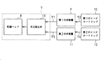
図1は、本実施形態におけるプリンタの概略を説明するための斜視図である。図2は、同プリンタの記録ヘッドへのインクの供給系を説明するためのブロック図である。
Hereinafter, an embodiment embodying the present invention will be described with reference to FIGS.
FIG. 1 is a perspective view for explaining an outline of a printer according to the present embodiment. FIG. 2 is a block diagram for explaining an ink supply system to the recording head of the printer.
図1に示すように、液体噴射装置としてのプリンタ1は、略直方形状のフレーム2を備えている。このフレーム2の上面には、給紙トレイ3が設けられ、さらに、フレーム2の前面には、排紙トレイ4が設けられている。この給紙トレイ3及び排紙トレイ4は、図示しないヒンジ構造によってフレーム2に対して折り畳み収容可能となるように構成されている。
As shown in FIG. 1, a printer 1 as a liquid ejecting apparatus includes a substantially
このフレーム2内には、その長手方向にプラテン5が配設され、このプラテン5上には、図示しない紙送り機構によって、給紙トレイ3からフレーム2内に挿入された記録用紙が給送されるようになっている。そして、この給送された記録用紙は、排紙トレイ4からフレーム2外へ排出されるようになっている。
A
前記フレーム2内には、プラテン5と平行となるようにガイド部材6が架設されている。このガイド部材6には、同ガイド部材6に沿って移動可能なキャリッジ7が挿通支持されている。また、前記フレーム2には、キャリッジモータ(図示しない)が取着され、こ
のキャリッジモータは、一対のプーリ(図示しない)に掛け装されたタイミングベルト(図示しない)を介してキャリッジ7が駆動連結されている。このように構成することによって、キャリッジモータが駆動すると、その駆動力はタイミングベルトを介してキャリッジ7に伝達される。この駆動力を受けてキャリッジ7は、ガイド部材6に案内されプラテン5と平行(主走査方向)に往復移動するようになっている。
A
一方、前記キャリッジ7の下面(プラテン5と対向する面)には、液体噴射ヘッドとしての記録ヘッド8が設けられている。この記録ヘッド8は、前記記録用紙に対向するようにノズル形成面を有し、このノズル形成面には、1列あたりn個(nは自然数)のノズルからなるノズル列(いずれも図示せず)が6列形成されている。本実施例では、説明の便宜上1列あたりn個のノズルからなるノズル列を6列形成したが、この限りではなく1列あたりのノズルの数及びノズル列の数は、適宜変更しても良い。
On the other hand, a
このキャリッジ7は、フレーム2内に設置された第1の弁装置9に対してチューブT1を介して接続されていて、同第1の弁装置9は、フレーム2内に装着された第1のインクカートリッジ10に対してチューブT2を介して接続されている。さらに、キャリッジ7は、フレーム2内に設置された第2の弁装置11に対してチューブT3を介して接続されていて、同第2の弁装置11は、フレーム2内に装着された第2のインクカートリッジ12に対してチューブT4を介して接続されている。
The
図2に示すように、この第1のインクカートリッジ10は、チューブT2を介して第1の弁装置9にインクを供給するようになっている。第1の弁装置9に供給されたインクはチューブT1を介してキャリッジ7に設けた自己封止弁13に供給された後に、同自己封止弁13から記録ヘッド8に供給されるようになっている。また同様に、第2のインクカートリッジ12は、チューブT4を介して第2の弁装置11にインクを供給するようになっている。第2の弁装置11に供給されたインクはチューブT3を介してキャリッジ7の自己封止弁13に供給された後に、同自己封止弁13から記録ヘッド8に供給されるようになっている。
As shown in FIG. 2, the
この自己封止弁13は、記録ヘッド8に適宜インクを供給するためのものであって、同記録ヘッド8からインクが吐出されて同記録ヘッド8内に負圧が発生すると、開状態となって同記録ヘッド8内にインクを導入するようになっている。また反対に、記録ヘッド8内にインクがあって、前記負圧が発生していないときには、閉状態となって同記録ヘッド8内に導入されるインクの量を制限して、インクの過剰導入による各ノズルのインクの漏洩を抑制するようになっている。
The self-sealing
尚、本実施形態の第1のインクカートリッジ10は、ブラック、シアン、マゼンダをそれぞれ貯留するインクパック(図示しない)を備え、又第2のインクカートリッジ12は、イエロー、ライトシアン、ライトマゼンダをそれぞれ貯留するインクパック(図示しない)を備えている。そして、これら各インクパックは、フレーム2内に設けられた加圧ポンプ(図示しない)から、第1及び第2のインクカートリッジ10,12内に供給される加圧空気によって押圧されて、それぞれチューブT2,T4にインクを圧送するようになっている。即ち、第1のインクカートリッジ10からは、ブラック、シアン、マゼンダが、又第2のインクカートリッジ12からは、イエロー、ライトシアン、ライトマゼンダが、それぞれ第1及び第2の弁装置9,11を介して記録ヘッド8に供給されるようになっている。そして、記録ヘッド8に流入したインクは、圧電素子(図示しない)によって加圧されて各ノズルからインク滴としてそれぞれ吐出されることによって、ドットを形成するようになっている。
Note that the
前記プリンタ1では、キャリッジ7を往復移動させながらインク滴を記録用紙に吐出さ
せ印刷するための領域を印刷領域としている。さらに、プリンタ1には、非印刷時にキャリッジ7を退避させてノズルをクリーニングするための非印刷領域が設けられ、この非印刷領域には、図1に示すように、キャップホルダ14が設けられている。
In the printer 1, an area for printing by ejecting ink droplets onto a recording sheet while reciprocating the
キャップホルダ14には、記録ヘッド8のノズル形成面と対向するように、キャップ部材15が設けられている。このキャップ部材15は、記録ヘッド8のノズルから吐出されるインクを受け止めるためのものである。そして、キャップホルダ14は、図示しない駆動機構を介してキャップ部材15を移動させて、同キャップ部材15の可撓性を有する当接部(図示しない)を記録ヘッド8のノズル形成面に密着させることによって、各ノズルを封止するようになっている。このキャップ部材15には、図示しないが、同キャップ部材15内と連通する連通孔を備えた接続部が形成されていて、同接続部には、チューブT5を介して吸引ポンプ16の吸引口が接続されている。この吸引ポンプ16は、チューブT5を介してキャップ部材15内に負圧をかけるためのものであって、駆動することで記録ヘッド8の各ノズルから同キャップ部材15内に吐出されたインクを吸引するようになっている。吸引ポンプ16の排出口(図示しない)には、チューブT6を介して廃インクタンク17が接続されている。この廃インクタンク17は、キャップ部材15から吸引されたインクを貯留するためのタンクである。
A
このように構成することによって、キャップ部材15によるノズルの封止の際に吸引ポンプ16が駆動すると、同ノズルには、キャップ部材15を介して負圧がかかりインクが吸引される。そして、吸引されたインクは、キャップ部材15からチューブT5、吸引ポンプ16、チューブT6を順に流動した後に、廃インクタンク17内に流入し廃インクとして貯留される。
With this configuration, when the
次に、上記した第1及び第2の弁装置9,11の構成を図3〜図7に従って説明する。
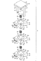
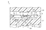
図3は、本実施形態の弁装置の構成を説明するための斜視図である。図4は、図3のA−A線方向の断面図である。図5は、同弁装置の構成を説明するための分解斜視図である。図6及び図7は、それぞれ図3のA−A線方向の部分断面図である。尚、本実施形態の第2の弁装置11は、第1の弁装置9に比べてその構造に差異がなく同様に構成されているため、説明の便宜上、ここでは第1の弁装置9についてのみ説明をして第2の弁装置11については省略する。
Next, the configuration of the first and
FIG. 3 is a perspective view for explaining the configuration of the valve device of the present embodiment. 4 is a cross-sectional view taken along line AA in FIG. FIG. 5 is an exploded perspective view for explaining the configuration of the valve device. 6 and 7 are partial cross-sectional views in the AA line direction of FIG. Note that the second valve device 11 of the present embodiment has the same structure with no difference in structure compared to the
図3及び図4に示すように、第1の弁装置9は、第1〜第3の逆止弁20〜22と、これら第1〜第3の逆止弁20〜22を連結固定する連結部材23とを備えている。この第1〜第3の逆止弁20〜22は、それぞれ同様の構造となっていて、それぞれ略直方形状の本体ケース24、フィルム25、受圧板26、シール部27、コイルバネ28を備えている。
As shown in FIGS. 3 and 4, the
この本体ケース24には、円環状の凹部29が凹設されていて、同凹部29には、その開口部に沿って円環状の溶着部30が立設されている。そして、溶着部30には、フィルム25が凹部29側に撓むように溶着されていて、同凹部29の開口部を被覆し封止することによってバルブ室31を形成している。このフィルム25は、樹脂等のガスバリア性及び可撓性を有する材料から構成されていて、溶着されることで、同フィルム25の中心部が、凹部29の底面29aに対して往復移動が可能となっている。そして、このフィルム25の中心部であって、バルブ室31側には、受圧板26が固着されていて、同受圧板26には、シール部27が固着されている。このシール部27は、ゴム等の可撓性を有する材料から構成されている。そして、このシール部27は、円環状の凹部29に囲まれた内側に円筒状に突出形成された凸部32と相対向するようになっていて、フィルム25がバルブ室31側に撓んでいるときに、同凸部32の上端部と当接するようになっている。
The
一方、本体ケース24には、図3及び図5に示すように、前記チューブT2を接続するための円筒状のインク導入部33及び前記チューブT1を接続するための円筒状のインク導出部34が延出形成されている。このインク導入部33及びインク導出部34は、それぞれの軸心を貫通する連通孔33a,34a(図5参照)を備えている。連通孔33aは、図4に示すように、本体ケース24の凹部29の底面29aに貫通するように形成された第1の流路35と連通し、同第1の流路35を介してバルブ室31に連通するようになっている。また、連通孔34aは、前記凸部32の軸心を貫通するように形成された第2の流路36と連通し、同第2の流路36を介してバルブ室31に連通するようになっている。
On the other hand, as shown in FIGS. 3 and 5, the
このように構成することによって、第1のインクカートリッジ10から供給されるインクは、チューブT2、インク導入部33の連通孔33a、第1の流路35を順に流動した後、バルブ室31に導入される。そして、バルブ室31に導入されたインクは、凸部32に形成された第2の流路36から、インク導出部34の連通孔34a、チューブT1、自己封止弁13を順に流動した後、記録ヘッド8に供給されるようになっている。
With this configuration, the ink supplied from the
また、前記シール部27が凸部32と当接しているときでは、前記第2の流路36は、同シール部27によって封止されて、このインクの流動は遮断された状態(非連通状態)となる。また、シール部27が、凸部32から離間しているときでは、このインクは流動可能な状態(連通状態)となる。
When the
そして、本実実施形態では、このように構成された本体ケース24を、第1〜第3の逆止弁20〜22として3つを重ね合わせることで、第1の弁装置9を構成するようになっている。詳しくは、図5に示すように、本体ケース24の底部24aの4隅には、四角柱状の脚部37が延出形成されている。この脚部37は、本体ケース24を重ね合わせた際に、隣接する本体ケース24との間隔Dを形成するためのものである。さらに、この4つの脚部37の内2つには、図5における下方向に円柱状の係合部38が突出形成されている。この係合部38は、隣接する本体ケース24の上面24bに凹設された嵌合溝39に嵌挿されるようになっている。即ち、第1の逆止弁20の係合部38は、第2の逆止弁21の嵌合溝39に嵌挿され、同第2の逆止弁21の係合部38は、第3の逆止弁22の嵌合溝39に嵌挿される。これによって、第1の逆止弁20の本体ケース24は、第2の逆止弁21の本体ケース24と間隔Dをあけて重なり合って、同第2の逆止弁21のフィルム25を覆うように位置する。同様に、第2の逆止弁21の本体ケース24は、第3の逆止弁22の本体ケース24と間隔Dをあけて重なり合って、同第3の逆止弁22のフィルム25を覆うように位置する。
In the present embodiment, the
他方、前記連結部材23は、蓋部40を備えていて、同蓋部40の両端からは図5における下方向にアーム41,42が延出形成されている。このアーム41,42の長さは、前記第1〜第3の逆止弁20〜22を重ね合わせた状態で包括することができるように設定されている。そして、その先端部には、それぞれ爪部41a,42aが形成されていている。さらに、蓋部40の底部40aの4隅には、第1の逆止弁20の本体ケース24と間隔Dを形成するための四角柱状の脚部43が延出形成されていて、同脚部43のうち2つには、図5における下方向に円柱状の係合部44が突出形成されている。この係合部44は、第1の逆止弁20の嵌合溝39に嵌挿されるようになっている。そして、連結部材23は、第1〜第3の逆止弁20〜22を重ねた状態から、第1の逆止弁20のフィルム25を覆うとともに、アーム41,42の爪部41a,42aを第3の逆止弁22の底部24aに係合させることによって、同第1〜第3の逆止弁を一体に連結固定する。
On the other hand, the connecting
また、図4に示すように、連結部材23の蓋部40の底部40aには円環状のバネ座45が突出形成されている。さらに、第1及び第2の逆止弁20,21の底部24aには、
同じく円環状のバネ座46がそれぞれ突出形成されている。このバネ座45,46は、コイルバネ28の上端部を支持するためのものであって、前記フィルム25の中心に固着された受圧板26と対向するようになっている。そして、バネ座45,46にそれぞれ取着されたコイルバネ28の下端部は、フィルム25を介して受圧板26に支持されるようになっている。これによって、連結部材23の蓋部40と第1の逆止弁20のフィルム25との間には、コイルバネ28が取着される。さらに、第1の逆止弁20の本体ケース24と第2の逆止弁21のフィルム25との間、及び第2の逆止弁21の本体ケース24と第3の逆止弁22のフィルム25との間においても、それぞれコイルバネ28が取着される。
As shown in FIG. 4, an
Similarly, annular spring seats 46 are formed to protrude. The spring seats 45 and 46 are for supporting the upper end portion of the
これによって、第1〜第3の逆止弁20〜22の各受圧板26には、それぞれフィルム25を介してコイルバネ28からの付勢力が加わってバルブ室31側に付勢されるようになっている。そして、この付勢によって受圧板26に固着されているシール部27は、前記凸部32に密着し第2の流路36を封止することで、バルブ室31を非連通状態とすることができる。また、コイルバネ28の付勢力は、シール部27を凸部32に当接させることができるように、受圧板26をバルブ室31側(図5における下方向)に付勢する程度に設定されていて、同バルブ室31側から上方向に所定の力が加わるとフィルム25が撓むように設定されている。尚、本実施形態における所定の力とは、第1及び第2のインクカートリッジ10,12からバルブ室31に導入されるインクの圧力である。
As a result, the
つまり、図6に示すように、バルブ室31内にインクが導入されたことによって、同インクによりフィルム25(受圧板26)が上方向に押圧されると、これに応じてコイルバネ28は撓むので、シール部27は、凸部32から離間してバルブ室31を連通状態とする。一方、図7に示すように、このバルブ室31内のインクが、第2の流路36から導出されて同インクによる受圧板26の押圧が消失されると、シール部27は、凸部32に当接してバルブ室31を非連通状態とする。
That is, as shown in FIG. 6, when ink is introduced into the
つまり、第1〜第3の逆止弁20〜22、即ち第1の弁装置9は、前記加圧ポンプの加圧によって第1のインクカートリッジ10からインクが供給されて、各バルブ室31にインクが導入されると、連通状態となって記録ヘッド8に向けてインクを供給する。この記録ヘッド8に導入されるインクは、上述したように、自己封止弁13によって制限される。従って、加圧ポンプの加圧が継続し、インクの供給が継続されている間は、各バルブ室31にはインクが導入されている状態となっているので、第1の弁装置9は、この連通状態を維持する。
That is, the first to
反対に、この連通状態から加圧ポンプの加圧が停止し、第1のインクカートリッジ10からのインクの供給が停止されると、各バルブ室31内のインクは、チューブT2を介して第1のインクカートリッジ10側に若干逆流する。これによって、各バルブ室31内の各受圧板26の押圧が消失するので、第1の弁装置9は非連通状態となる。また、非連通状態となっている際に、第2の流路36を介して記録ヘッド8側からバルブ室31に逆流しようとするインクの圧力は前記所定の力より小さいので、コイルバネ28はこの圧力に抗して縮まない。これによって、シール部27は凸部32との当接状態を維持できるので、記録ヘッド8側からバルブ室31へのインクの逆流は抑制されるようになっている。
On the contrary, when the pressurization of the pressurizing pump is stopped from this communication state and the supply of ink from the
また、上述したように、吸引ポンプ16により記録ヘッド8のノズルに負圧をかけた場合、記録ヘッド8内のインクは吸引されて前記キャリッジ7内の自己封止弁13は開状態となる。その結果、この第1〜第3の逆止弁20〜22の各バルブ室31内には、その第2の流路36を介してこの負圧がかかる。このとき、シール部27は、この第2の流路36からの負圧によって凸部32に引き付けられて当接するので、第1の弁装置9は非連通状態を維持することができる。
As described above, when a negative pressure is applied to the nozzles of the
次に、上記のように構成した第1及び第2の弁装置9,11を備えたプリンタ1のクリーニング方法としてのクリーニング操作について説明する。
プリンタ1は、ノズルのクリーニングを行う際には、加圧ポンプを停止させて第1及び第2のインクカートリッジ10,12から第1及び第2の弁装置9,11へのインクの供給を停止する。これに応じて、第1及び第2の弁装置9,11の各バルブ室31には、インクが導入されないので同第1及び第2の弁装置9,11は非連通状態となる(第1のステップ)。
Next, a cleaning operation as a cleaning method of the printer 1 including the first and
When cleaning the nozzles, the printer 1 stops the pressurization pump and stops the supply of ink from the first and
次に、プリンタ1は、キャップ部材15の当接部を記録ヘッド8のノズル形成面に当接させて各ノズルを封止した後に、吸引ポンプ16を駆動させて、記録ヘッド8のノズルに負圧をかける。このとき、自己封止弁13は、記録ヘッド8内に負圧がかかったことに応じて連通状態となる。これによって、この負圧は自己封止弁13を介して、第1及び第2の弁装置9,11の各第2の流路36にまで到達する。
Next, the printer 1 abuts the contact portion of the
そして、所定の時間が経過すると、記録ヘッド8内から自己封止弁13内及び第2の流路36に至るまでに負圧が蓄積される(第2のステップ)。プリンタ1は、加圧ポンプを再び駆動して第1及び第2のインクカートリッジ10,12からインクの供給を再開する。これによって、第1及び第2の弁装置9,11の各バルブ室31には、インクが導入されるので、同第1及び第2の弁装置9,11は連通状態となる。このとき、各バルブ室31に導入されるインクは、各第2の流路36にまで到達した負圧によって吸引されて、同第2の流路36、自己封止弁13を介して記録ヘッド8に向けて一気に流動した後、記録ヘッド8のノズルから吐出されてキャップ部材15に受け止められる(第3のステップ)。これによって、プリンタ1は、前記第1〜第3のステップに従ってクリーニング操作を行うことによって、記録ヘッド8内に気泡が侵入している場合であっても、同気泡を、ノズルから吐出されるインクとともにキャップ部材15に排出することができる。
When a predetermined time elapses, negative pressure is accumulated from the inside of the
そして、プリンタ1は、所定の時間が経過すると吸引ポンプ16を停止させた後に、記録ヘッド8からキャップ部材15を離間させノズルの封止を解除してクリーニングを終了する。尚、本実施形態における所定の時間とは、上述したクリーニングを好適に行えるように予め設定された時間である。
Then, the printer 1 stops the
以上、上記した本実施形態によれば、以下の効果を奏する。
(1)本実施形態では、第1の弁装置9を第1のインクカートリッジ10からインクの供給があると連通状態となり、この供給が停止されると非連通状態となるように構成した。さらに、第2の弁装置11も、第1の弁装置9と同様に、第2のインクカートリッジ12からのインクの供給があると連通状態となり、この供給が停止されると非連通状態となるように構成した。つまり、この第1及び第2の弁装置9,11の連通状態又は非連通状態を第1及び第2のインクカートリッジ10,12からのインクの供給によって、制御するようにした。
As mentioned above, according to this embodiment mentioned above, there exist the following effects.
(1) In this embodiment, the
従って、第1及び第2の弁装置9,11を電磁ソレノイドバルブから構成した場合に比べて、駆動電源等の部品点数を低減することができる。この結果、プリンタ1は、小型化及び製造コストの低減を実現することができる。
Therefore, the number of parts such as a drive power source can be reduced as compared with the case where the first and
さらに、第1及び第2の弁装置9,11は、駆動電源を必要としないので、例えば、プリンタ1の未使用時に第1及び第2のインクカートリッジ10,12の交換を行う場合であっても、記録ヘッド8内及び自己封止弁13内のインクが、第1及び第2のインクカートリッジ10,12側に逆流することを低減することができる。従って、記録ヘッド8内及び自己封止弁13内にてインクが乾燥し固化することを抑制することができ、このイン
クの固化に起因するノズルの目詰まり等を抑制することができる。この結果、プリンタ1はノズルから正確にインクを吐出することができる。
(2)本実施形態では、第1の弁装置9を、第1〜第3の逆止弁20〜22として、それぞれ本体ケース24、フィルム25、受圧板26、シール部27、コイルバネ28から構成した。さらに、第2の弁装置11を、第1の弁装置9と同様に構成した。このように同部材から構成することによって、第1及び第2の弁装置9,11の製造コストを低減することができる。
(3)本実施形態では、本体ケース24の底部24aにバネ座45を一体形成した。これによって、新たに部品を設ける必要がなく、隣接する本体ケース24のコイルバネ28の上端部を支持することができる。この結果、第1及び第2の弁装置9,11の部品点数を低減することができるので、同第1及び第2の弁装置9,11の小型化及び製造コストの低減を実現することができる。
(4)本実施形態の連結部材23は、その蓋部40の底部40aに、第1〜第3の逆止弁20〜22を係止した際に第1の逆止弁20のコイルバネ28を支持するバネ座46を形成した。これによって、連結部材23は、新たに部品を設ける必要がなく第1の逆止弁20のコイルバネ28の上端部を支持することができる。この結果、第1〜第3の逆止弁20〜22及び連結部材23から構成される第1の弁装置9と、同第1の弁装置9と同様に構成される第2の弁装置11は、その部品点数を低減することができ、小型化及び製造コストの低減を実現することができる。
(5)本実施形態の第1〜第3の逆止弁20〜22では、各本体ケース24の底部24aに脚部37を形成し、さらに、連結部材23の蓋部40の底部40aに脚部43を形成した。これによって、第1〜第3の逆止弁20〜22及び連結部材23は。互いに間隔Dを開けて重なり合うことができる。これによって、この間隔D内にコイルバネ28を配設することができ、第1〜第3の逆止弁20〜22のレイアウトの自由度を向上させることができる。この結果、第1〜第3の逆止弁20〜22及び連結部材23を備える第1の弁装置9の小型化を実現することができる。さらに、第1の弁装置9と同様に構成された第2の弁装置11の小型化を実現することができる。
(6)本実施形態では、第1〜第3の逆止弁20〜22の脚部37に係合部38を形成し、また連結部材23の脚部43に係合部44を形成した。さらに、第1〜第3の逆止弁20〜22の各本体ケース24の上面24bに、嵌合溝39を凹設して、係合部38,44とそれぞれ係合できるように構成した。これによって、第1〜第3の逆止弁20〜22及び連結部材23を互いに重ね合わせて係合することができ、さらに位置決めすることができるので、第1の弁装置9を形成する際の作業性を向上させることができる。また、第1の弁装置9と、同様に構成される第2の弁装置11を形成する際の作業性も向上させることができる。
Further, since the first and
(2) In this embodiment, the
(3) In this embodiment, the
(4) The connecting
(5) In the first to
(6) In this embodiment, the engaging
尚、発明の実施の形態は、上記各実施形態に限定されるものではなく、以下のように変更してもよい。
・上記実施形態では、フィルム25のバルブ室31側に受圧板26を固着し、コイルバネ28の下端部を、同フィルム25を介して支持するように構成したが、この限りではなく、フィルム25の上面に固着してコイルバネ28の下端部を直接支持するように構成してもよい。
In addition, embodiment of invention is not limited to said each embodiment, You may change as follows.
In the above embodiment, the
・上記実施形態では、フィルム25に受圧板26を介してシール部27を固着したが、この限りではなく、同受圧板26を設けないで、同フィルム25にシール部27を直接固着してもよい。また、受圧板26及びシール部27を設けなくてもよい。このとき、フィルム25を、第2の流路36を封止することができるように適宜変更することが望ましい。
In the above embodiment, the
・上記実施形態では、第1〜第3の逆止弁20〜22を連結部材23によって、一体に
係止することで第1の弁装置9を構成し、第2の弁装置11も同様に構成したが、この限りではなく、第1及び第2の弁装置9,11を一体となるように構成してもよい。このとき、連結部材23の構成を適宜変更することが望ましい。
-In the said embodiment, the
・上記実施形態では、本体ケース24の脚部37に係合部38を形成し、同本体ケース24の嵌合溝39と係合するように構成したが、この限りではなく、例えば、脚部37に嵌合溝39を形成し、同本体ケース24に係合部38を形成して係合可能となるように構成してもよい。
In the above embodiment, the engaging
・上記実施形態では、連結部材23の脚部43に係合部44を形成し、第1の逆止弁20の本体ケース24の嵌合溝39と係合するように構成したが、この限りではなく、例えば、脚部43に嵌合溝39を形成し、同本体ケース24に係合部38を形成して係合可能となるように構成してもよい。
In the above embodiment, the engaging
・上記実施形態の第1〜第3の逆止弁20〜22では、凸部32にシール部27を当接させることによって、第2の流路36を封止しバルブ室31を非連通状態とするように構成したが、この限りではなく、シール部27によって第1の流路35を封止することで同バルブ室31を非連通状態とすることができるように構成してもよい。このとき、第1〜第3の逆止弁20〜22の構成を適宜変更することが望ましい。
In the first to
・上記各実施形態では、液体噴射装置をプリンタ1に具体化したが、この限りではなく、他の液体を噴射する液体噴射装置に具体化するようにしてもよい。例えば、液晶ディスプレイ、ELディスプレイ及び面発光ディスプレイの製造などに用いられる電極材や色材などの液体を噴射する液体噴射装置、バイオチップ製造に用いられる生体有機物を噴射する液体噴射装置、精密ピペットとしての試料噴射装置であってもよい。 In each of the above embodiments, the liquid ejecting apparatus is embodied in the printer 1. However, the present invention is not limited to this, and the liquid ejecting apparatus may be embodied in a liquid ejecting apparatus that ejects another liquid. For example, as a liquid ejecting apparatus for ejecting liquids such as electrode materials and color materials used in the manufacture of liquid crystal displays, EL displays, and surface-emitting displays, as a liquid ejecting apparatus for ejecting bioorganic materials used in biochip manufacturing, and as precision pipettes The sample injection device may be used.
1…液体噴射装置としてのプリンタ、9…弁装置としての第1の弁装置、11…弁装置としての第2の弁装置、10…液体収容体としての第1のインクカートリッジ、12…液体収容体としての第2のインクカートリッジ、16…吸引手段としての吸引ポンプ、20〜22…弁体としての第1〜第3の逆止弁、23…連結部材、24…本体ケース、25…フィルム材、26…受圧板、27…開閉手段及びシール部材としてのシール部、28…付勢手段及びバネ部材としてのコイルバネ、29…凹部、31…流体収容室としてのバルブ室、33a…導入部としての第1の流路、34b…導出部としての第2の流路、37…本体ケースに設けられた間隔保持手段としての脚部、38…位置決め手段及び第1の接続部としての係合部、39…位置決め手段及び第2の接続部としての嵌合溝、43…連結部材に設けられた間隔保持手段としての脚部、45…連結部材に形成されるバネ座、46…本体ケースに形成されるバネ座、D…間隔。 DESCRIPTION OF SYMBOLS 1 ... Printer as a liquid ejecting apparatus, 9 ... 1st valve apparatus as a valve apparatus, 11 ... 2nd valve apparatus as a valve apparatus, 10 ... 1st ink cartridge as a liquid container, 12 ... Liquid accommodation Second ink cartridge as a body, 16... Suction pump as a suction means, 20 to 22... First to third check valves as a valve body, 23... Connecting member, 24. , 26 ... pressure receiving plate, 27 ... sealing part as opening / closing means and sealing member, 28 ... coil spring as urging means and spring member, 29 ... concave part, 31 ... valve chamber as fluid storage chamber, 33a ... as introduction part 1st flow path, 34b ... 2nd flow path as derivation | leading-out part, 37 ... Leg part as space | interval holding means provided in main body case, 38 ... Positioning means and engagement part as 1st connection part, 39 ... Position Fitting groove as means and second connection part, 43... Leg part as interval holding means provided in the connection member, 45... Spring seat formed in the connection member, 46 .. spring seat formed in the body case , D ... interval.
Claims (13)
前記流体収容室に流体を導入する導入部と、
前記流体収容室から流体を導出する導出部と、
前記導入部及び前記導出部に形成した流路の少なくとも一方を開閉することで、同導入部と同導出部との間の流体の流量を調整する開閉手段とを備え、
前記フィルム材を介して前記開閉手段を付勢して、前記流路の少なくとも一方を閉路するとともに、
前記導入部から前記流体収容室内に導入された流体の圧力が、前記フィルム材に付与されると、同付勢を緩和し、前記流路を開路する付勢手段を備えたことを特徴とする弁体。 A fluid storage chamber for storing a fluid by covering the recess formed in the main body case with a film material;
An introduction part for introducing a fluid into the fluid storage chamber;
A deriving unit for deriving a fluid from the fluid storage chamber;
Opening and closing means for adjusting the flow rate of fluid between the introduction part and the lead-out part by opening and closing at least one of the flow paths formed in the introduction part and the lead-out part,
Energizing the opening and closing means through the film material, and closing at least one of the flow paths,
When the pressure of the fluid introduced from the introduction part into the fluid storage chamber is applied to the film material, the film member is provided with a biasing means that relaxes the bias and opens the flow path. Valve body.
前記流体収容室に流体を導入する導入部と、
前記流体収容室から流体を導出する導出部と、
前記導入部及び前記導出部に形成した流路の少なくとも一方を開閉することで、同導入部と同導出部との間の流体の流量を調整する開閉手段と、
前記フィルム材を介して前記開閉手段を付勢して、前記流路の少なくとも一方を閉路させる付勢手段とを備えた弁体を、少なくとも2つ以上重ね合わせることによって形成される弁装置であって、
前記本体ケースは、前記弁体を重ね合わせた際に、隣接する弁体の付勢手段を支持することを特徴とする弁装置。 A fluid storage chamber for storing a fluid by covering the concave portion of the main body case with a film material;
An introduction part for introducing a fluid into the fluid storage chamber;
A deriving unit for deriving a fluid from the fluid storage chamber;
Opening and closing means for adjusting the flow rate of the fluid between the introduction part and the lead-out part by opening and closing at least one of the flow paths formed in the introduction part and the lead-out part;
The valve device is formed by overlapping at least two valve bodies each including biasing means for biasing the opening / closing means via the film material and closing at least one of the flow paths. And
The main body case supports an urging means of an adjacent valve body when the valve bodies are overlapped with each other.
前記付勢手段は、バネ部材であって、前記本体ケースには、同バネ部材を支持するバネ座が形成されていることを特徴とする弁装置。 The valve device according to claim 2,
The urging means is a spring member, and the main body case is formed with a spring seat for supporting the spring member.
前記開閉手段は、前記フィルム材に固着された可撓性を有するシール部材であって、同シール部材は、前記導入部及び前記導出部に形成した前記流路の少なくとも一方を開閉して、前記流体の流量を調整することを特徴とする弁装置。 The valve device according to claim 2 or 3,
The open / close means is a flexible seal member fixed to the film material, and the seal member opens and closes at least one of the flow paths formed in the introduction portion and the lead-out portion, and A valve device for adjusting a flow rate of a fluid.
前記フィルム材の表又は裏の少なくとも一方には、前記バネ部材を受け止める受圧板を設けたことを特徴とする弁装置。 The valve device according to claim 4,
A valve device, wherein a pressure receiving plate for receiving the spring member is provided on at least one of the front and back of the film material.
前記バネ部材は、コイルバネであって、前記本体ケースには、隣接する前記弁体の本体ケースとの間に前記コイルバネを取着するための間隔を保持する間隔保持手段を設けたことを特徴とする弁装置。 The valve device according to any one of claims 3 to 5,
The spring member is a coil spring, and the main body case is provided with interval holding means for holding an interval for attaching the coil spring between the main body cases of the adjacent valve bodies. Valve device to do.
前記弁体を重ね合わせる際に、各弁体の位置決めをする位置決め手段を設けたことを特徴とする弁装置。 The valve device according to any one of claims 2 to 6,
A valve device comprising a positioning means for positioning each valve body when the valve bodies are overlapped.
前記位置決め手段は、前記本体ケースに設けられた第1の接続部及び第2の接続部であって、同第1の接続部は隣接する弁体の第2の接続部に接続されることを特徴とする弁装置。 The valve device according to claim 7,
The positioning means is a first connecting portion and a second connecting portion provided in the main body case, and the first connecting portion is connected to a second connecting portion of an adjacent valve body. Characteristic valve device.
前記弁体を重ね合わせた状態で包括して連結する連結部材を備え、
同連結部材は、前記弁装置の端部に位置する弁体の付勢手段を支持することを特徴とする弁装置。 The valve device according to any one of claims 2 to 8,
Comprising a connecting member for comprehensively connecting the valve bodies in an overlapped state,
The connecting member supports a biasing means of a valve body located at an end of the valve device.
前記付勢手段は、バネ部材であって、前記連結部材には、前記バネ部材を支持するバネ座が形成されていることを特徴とする弁装置。 The valve device according to claim 9,
The urging means is a spring member, and the connecting member is formed with a spring seat for supporting the spring member.
前記バネ部材は、コイルバネであって、
前記連結部材には、同連結部材と、前記弁体との間に前記コイルバネを取着するための間隔を保持する間隔保持手段を設けたことを特徴とする弁装置。 The valve device according to claim 10,
The spring member is a coil spring,
The valve device according to claim 1, wherein the connecting member is provided with an interval holding means for holding an interval for attaching the coil spring between the connecting member and the valve body.
液体を噴射する液体噴射ヘッドと、
前記液体を貯留するとともに、前記弁装置を介して前記液体噴射ヘッドに液体を供給する液体収容体とを備えたことを特徴とする液体噴射装置。 A liquid ejecting apparatus comprising the valve device according to any one of claims 2 to 11,
A liquid ejecting head for ejecting liquid;
A liquid ejecting apparatus comprising: a liquid container that stores the liquid and supplies the liquid to the liquid ejecting head via the valve device.
液体を噴射する液体噴射ヘッドと、
前記液体を貯留するとともに、前記弁装置を介して前記液体噴射ヘッドに液体を供給する液体収容体と、
前記液体噴射ヘッドに負圧をかけて同液体噴射ヘッドから前記液体を吸引する吸引手段とを備えた液体噴射装置のクリーニング方法であって、
前記液体収容体からの前記液体の供給を停止し、前記弁装置を非連通状態とする第1のステップと、
前記第1のステップから前記吸引手段によって液体噴射ヘッドに対して負圧をかけて、同液体噴射ヘッドに同負圧を蓄積する第2のステップと、
前記第2のステップから前記液体収容体からの前記液体の供給を再開し、前記弁装置を連通状態として同液体噴射ヘッドから前記液体を噴射させる第3のステップと
からなることを特徴とする液体噴射装置のクリーニング方法。 A valve device according to any one of claims 2 to 11, comprising:
A liquid ejecting head for ejecting liquid;
A liquid container that stores the liquid and supplies the liquid to the liquid ejecting head via the valve device;
A cleaning method for a liquid ejecting apparatus, comprising: suction means for sucking the liquid from the liquid ejecting head by applying a negative pressure to the liquid ejecting head;
A first step of stopping the supply of the liquid from the liquid container and bringing the valve device into a non-communication state;
A second step of applying a negative pressure to the liquid jet head by the suction means from the first step and accumulating the negative pressure in the liquid jet head;
The liquid comprises: a third step of resuming the supply of the liquid from the liquid container from the second step and ejecting the liquid from the liquid ejecting head with the valve device in a communicating state. Cleaning method for spray device.
Priority Applications (1)
| Application Number | Priority Date | Filing Date | Title |
|---|---|---|---|
| JP2004115973A JP2005297330A (en) | 2004-04-09 | 2004-04-09 | Valve body, valve device, liquid ejecting apparatus, and cleaning method for liquid ejecting apparatus |
Applications Claiming Priority (1)
| Application Number | Priority Date | Filing Date | Title |
|---|---|---|---|
| JP2004115973A JP2005297330A (en) | 2004-04-09 | 2004-04-09 | Valve body, valve device, liquid ejecting apparatus, and cleaning method for liquid ejecting apparatus |
Publications (1)
| Publication Number | Publication Date |
|---|---|
| JP2005297330A true JP2005297330A (en) | 2005-10-27 |
Family
ID=35329472
Family Applications (1)
| Application Number | Title | Priority Date | Filing Date |
|---|---|---|---|
| JP2004115973A Pending JP2005297330A (en) | 2004-04-09 | 2004-04-09 | Valve body, valve device, liquid ejecting apparatus, and cleaning method for liquid ejecting apparatus |
Country Status (1)
| Country | Link |
|---|---|
| JP (1) | JP2005297330A (en) |
Cited By (5)
| Publication number | Priority date | Publication date | Assignee | Title |
|---|---|---|---|---|
| JP2007210299A (en) * | 2006-02-13 | 2007-08-23 | Seiko Epson Corp | Valve device and liquid injection device |
| JP2008044253A (en) * | 2006-08-17 | 2008-02-28 | Seiko Epson Corp | Ink supply mechanism and recording apparatus including the same |
| JP2010274470A (en) * | 2009-05-27 | 2010-12-09 | Seiko Epson Corp | Self-sealing valve, liquid ejecting apparatus including the same, electronic device, and liquid filling method |
| US8197040B2 (en) | 2008-07-23 | 2012-06-12 | Seiko Epson Corporation | Liquid supply device and liquid ejecting apparatus |
| CN114103472A (en) * | 2021-12-10 | 2022-03-01 | 苏州希盟科技股份有限公司 | Ink supply system |
-
2004
- 2004-04-09 JP JP2004115973A patent/JP2005297330A/en active Pending
Cited By (5)
| Publication number | Priority date | Publication date | Assignee | Title |
|---|---|---|---|---|
| JP2007210299A (en) * | 2006-02-13 | 2007-08-23 | Seiko Epson Corp | Valve device and liquid injection device |
| JP2008044253A (en) * | 2006-08-17 | 2008-02-28 | Seiko Epson Corp | Ink supply mechanism and recording apparatus including the same |
| US8197040B2 (en) | 2008-07-23 | 2012-06-12 | Seiko Epson Corporation | Liquid supply device and liquid ejecting apparatus |
| JP2010274470A (en) * | 2009-05-27 | 2010-12-09 | Seiko Epson Corp | Self-sealing valve, liquid ejecting apparatus including the same, electronic device, and liquid filling method |
| CN114103472A (en) * | 2021-12-10 | 2022-03-01 | 苏州希盟科技股份有限公司 | Ink supply system |
Similar Documents
| Publication | Publication Date | Title |
|---|---|---|
| CN100364773C (en) | Method for producing a liquid container and liquid container | |
| US8915580B2 (en) | Liquid supplying apparatus and liquid ejecting apparatus | |
| US7384133B2 (en) | Liquid container capable of maintaining airtightness | |
| US20120182363A1 (en) | Flow path member, liquid ejecting head, and liquid ejecting apparatus | |
| WO2005061235A1 (en) | Valve device, pressure-reducing valve, carriage, liquid- jetting device, and valve device-producing method | |
| JP2007260947A (en) | Liquid supply device and liquid ejection device | |
| JP6821983B2 (en) | Liquid injection device | |
| US8746840B2 (en) | Maintenance device, fluid ejecting apparatus and maintenance method | |
| JP2010221491A (en) | Liquid supply device, liquid ejection device | |
| US20180292017A1 (en) | Flexible membrane mechanism, flow path member, liquid ejecting apparatus, and control method of flexible membrane | |
| JP2010208049A (en) | Fluid ejecting apparatus and valve unit | |
| US20200094570A1 (en) | Liquid ejecting apparatus and maintenance method of liquid ejecting apparatus | |
| JP2005297330A (en) | Valve body, valve device, liquid ejecting apparatus, and cleaning method for liquid ejecting apparatus | |
| US10029471B2 (en) | Liquid ejecting apparatus and method for controlling liquid ejecting apparatus | |
| JP2007260948A (en) | Liquid supply apparatus, liquid supply apparatus manufacturing method, and liquid ejecting apparatus | |
| JP4645070B2 (en) | Valve device and liquid injection device | |
| JP2007260949A (en) | Liquid supply device and liquid ejection device | |
| US7422308B2 (en) | Liquid ejection apparatus | |
| JP4296954B2 (en) | Circulation pump for liquid discharge device | |
| JP4915515B2 (en) | Liquid ejector | |
| JP5071196B2 (en) | Fluid ejection device and maintenance method for fluid ejection device | |
| JP2008238414A (en) | Liquid jet head | |
| JP4453364B2 (en) | Valve device and liquid injection device | |
| JP2009154299A (en) | Fluid ejection device and maintenance method for fluid ejection device | |
| JP2005343123A (en) | Pressure reducing valve, carriage and liquid ejecting apparatus |