JP2005297088A - Method and apparatus for marking in knurl pattern area - Google Patents
Method and apparatus for marking in knurl pattern area Download PDFInfo
- Publication number
- JP2005297088A JP2005297088A JP2004113109A JP2004113109A JP2005297088A JP 2005297088 A JP2005297088 A JP 2005297088A JP 2004113109 A JP2004113109 A JP 2004113109A JP 2004113109 A JP2004113109 A JP 2004113109A JP 2005297088 A JP2005297088 A JP 2005297088A
- Authority
- JP
- Japan
- Prior art keywords
- workpiece
- peripheral surface
- outer peripheral
- knurled
- pattern
- Prior art date
- Legal status (The legal status is an assumption and is not a legal conclusion. Google has not performed a legal analysis and makes no representation as to the accuracy of the status listed.)
- Granted
Links
Images



Landscapes
- Shaping Of Tube Ends By Bending Or Straightening (AREA)
- Shaping Metal By Deep-Drawing, Or The Like (AREA)
- Image Generation (AREA)
- Moulds For Moulding Plastics Or The Like (AREA)
Abstract
【課題】円柱状の被加工物の外周面にローレット模様を形成すると同時に、ローレット模様域内にこの模様がない無模様部分を設けると共に、この無模様部分に商標や商品番号、図柄などを刻印表示する方法及びその装置を提供する。
【解決手段】この丸形ダイスを回転動しつつ前記被加工物方向に押圧動することにより、前記被加工物1の外周面1aに網目、平目等のローレット模様を形成するローレット加工装置であって、しかも前記各丸形ダイスの外周面には、前記被加工物の外周面上の所定個所を前記ローレット模様がない無模様部1bにすることとなる前記ローレット目の省略部が設けられ、丸形ダイスの前記無模様部に配設した前記刻印版により、前記被加工物の外周面に、前記ローレット模様を形成すると共に、このローレット模様域内に、前記商標、商品番号、図柄等Cを刻印する。
【選択図】図5An object of the present invention is to form a knurled pattern on the outer peripheral surface of a cylindrical workpiece, and at the same time to provide a non-patterned part without this pattern in the knurled pattern area, and to display a trademark, a product number, a design, etc. on the non-patterned part And a method thereof.
A knurling apparatus for forming a knurled pattern such as a mesh or a flat pattern on an outer peripheral surface 1a of the workpiece 1 by rotating the round die in the direction of the workpiece while rotating. In addition, on the outer peripheral surface of each of the round dies, there is provided an omission portion of the knurled eye that makes the predetermined portion on the outer peripheral surface of the workpiece a non-patterned portion 1b without the knurled pattern, The knurled pattern is formed on the outer peripheral surface of the workpiece by the engraving plate disposed in the non-patterned portion of the round die, and the trademark, product number, design, etc. C are placed in the knurled pattern area. Engrave.
[Selection] Figure 5
Description
本発明は、締付け工具の円柱状把持部周面に滑り止めとして形成するローレット模様など、円柱状の被加工物の外周面にローレット加工を行なうもので、詳しくは、被加工物の外周面にローレット加工すると共に、ローレット模様域内にこのローレット模様が無い部分を設け、この無模様部に商標、品番や図柄などを刻印表示する方法及びその装置に関するものである。 The present invention performs knurling on the outer peripheral surface of a cylindrical workpiece such as a knurled pattern formed as a non-slip on the peripheral surface of the cylindrical gripping portion of the tightening tool, and more specifically, on the outer peripheral surface of the workpiece. The present invention relates to a method and an apparatus for performing knurling, providing a portion having no knurled pattern in the knurled pattern area, and displaying a mark, a product number, a pattern, and the like on the non-patterned portion.
締付け工具の円柱状把持部周面に滑り止めとして形成された網目状や平目状のローレット模様のごとく、円柱状の被加工物の外周面にローレット模様を加工する手段は、外周面に多条溝状のローレット目が周設された一対の丸形ダイスが回転軸を平行にした状態で配設されており、この両丸形ダイス間に被加工物を配置して、丸形ダイスを回転動すると共に、被加工物方向に押圧動することにより、被加工物の外周面にローレット模様を形成する公知の押転造による手段のほか、切削式手段などがある(参考として特許文献1、特許文献2、非特許文献3)。
There are many means for processing a knurled pattern on the outer peripheral surface of a cylindrical workpiece, such as a mesh-like or flat knurled pattern formed as a non-slip on the peripheral surface of the cylindrical gripping tool. A pair of round dies with groove-shaped knurls are arranged with the rotation axis in parallel, and the work piece is placed between the round dies to rotate the round dies. In addition to a known roll-forming means for forming a knurled pattern on the outer peripheral surface of the workpiece by moving in the direction of the workpiece while moving, there is a cutting-type means (for example,
締付け工具の円柱状把持部などに形成されたローレット模様は、網目(あや目とも称される)や平目などの目の種類や、粗目、中目、細目など目の粗密による態様の違いはあるが、概ね所定の加工域全面にわたって施されている。 The knurled pattern formed on the cylindrical gripping part of the tightening tool has different types depending on the type of eyes such as meshes (also referred to as aya) or flat eyes, and the density of the eyes such as coarse, medium, and fine. Is applied over the entire surface of the predetermined processing area.
本発明は、円柱状の被加工物の外周面にローレット模様を形成すると同時に、ローレット模様域内にこの模様がない無模様部分を設けると共に、この無模様部分に商標や商品番号、図柄などを刻印表示する方法及びその装置を提供するものである。 In the present invention, a knurled pattern is formed on the outer peripheral surface of a cylindrical workpiece, and at the same time, a non-patterned portion without the pattern is provided in the knurled pattern region, and a trademark, a product number, a design, etc. are imprinted on the non-patterned portion. A display method and an apparatus thereof are provided.
上記ローレット模様域内に刻印表示する方法は、外周面に多条溝状のローレット目が周設された一対の丸形ダイスが、回転軸を平行に配設されており、前記両丸形ダイスの間に円柱状の被加工物を配置して、この丸形ダイスを回転動しつつ前記被加工物方向に押圧動することにより、前記被加工物の外周面に網目、平目等のローレット模様を形成するローレット加工装置であって、しかも前記各丸形ダイスの外周面には、前記被加工物の外周面上の所定個所を前記ローレット模様がない無模様部にすることとなる前記ローレット目の省略部が設けられ、この省略部は、前記無模様部に、商標、商品番号、図柄など刻印表示する取外し可能な刻印板の配設手段を備えており、前記ローレット加工時における両丸形ダイスと被加工物の周面接触回転動にあって、前記被加工物の所定個所と前記各丸形ダイスの無模様部を合致させるこの両丸形ダイスの同期回転制御手段と、一方の丸形ダイスの前記無模様部に配設した前記刻印版により、前記被加工物の外周面に、前記ローレット模様を形成すると共に、このローレット模様域内に、前記商標、商品番号、図柄等を刻印することを特徴とするもので、その装置は、前記ローレット加工装置において、前記各丸形ダイスの外周面には、前記被加工物の外周面上の所定個所を前記ローレット模様がない無模様部にすることとなる前記ローレット目の省略部が設けられていると共に、この省略部は、前記無模様部に、商標、商品番号、図柄など刻印表示する取外し可能な刻印板の配設手段を備えており、しかも前記ローレット加工時における両丸形ダイスと被加工物の周面接触回転動にあって、前記被加工物の所定個所と前記各丸形ダイスの無模様部を合致させる、この両丸形ダイスの同期回転制御手段を備えているもので、更に前記装置のローレット目の省略部は、各丸形ダイスの外周面に穴を凹設すること及び、前記穴は、刻印版の嵌脱固定手段を備えていることを特徴とするものである。 In the method of marking and displaying in the knurled pattern area, a pair of round dies each having a multi-groove knurl around the outer peripheral surface are arranged in parallel with the rotation axis. By placing a cylindrical work piece between them and rotating the circular die while pressing it in the direction of the work piece, a knurled pattern such as a mesh or a flat pattern is formed on the outer peripheral surface of the work piece. In the knurling device to be formed, and on the outer peripheral surface of each of the round dies, a predetermined portion on the outer peripheral surface of the workpiece is formed as a non-patterned portion without the knurled pattern. An omission part is provided, and the omission part is provided with means for disposing a removable engraving plate on the non-patterned part to display a mark, a product number, a design, etc. And contact surface of workpiece A synchronous rotation control means for the two round dies that matches a predetermined portion of the workpiece and the non-patterned portion of each of the circular dies, and the non-patterned portion of one of the round dies. The knurling plate forms the knurled pattern on the outer peripheral surface of the workpiece, and the trademark, the product number, the design, etc. are imprinted in the knurled pattern area. In the knurl processing device, the knurl-shaped omission portion that makes a predetermined portion on the outer peripheral surface of the workpiece a non-patterned portion without the knurled pattern on the outer peripheral surface of each round die. The omission part is provided with means for disposing a removable engraving plate that displays a mark, a product number, a design, etc. on the non-patterned part, and both the knurling process A rotating control means for synchronous rotation of the round dies, which is in contact with the peripheral surface of the die and the workpiece, and matches a predetermined portion of the workpiece with a non-patterned portion of each of the round dies. Further, the knurled omission part of the apparatus is characterized in that a hole is provided in the outer peripheral surface of each round die, and the hole is provided with a fitting / detaching fixing means for the stamped plate. To do.
本発明における装置によれば、ローレット加工時における両丸形ダイスと被加工面の周面接触回転動にあって、両丸形ダイスの同期回転に伴ない、被加工物の外周面上の所定個所と合致する各丸形ダイスの外周面上の部位に、前記所定個所をローレット模様がない無模様部にすることとなるローレット目の省略部が設けられており、そしてこの省略部は、商標、商品番号や図柄などの刻印版が配設可能に構成され、一方の丸形ダイスに刻印版を配設固定して被加工物を加工すると、被加工物の外周面にローレット模様を形成すると共に、このローレット模様域内に商標などを刻印表示することができるのみか、図柄表示も可能であり、更に刻印版を取外した状態で加工することにより、ローレット模様域内に無模様個所が表出され、これが柄ともなるものであり、しかも所望の形状、大きさ、配置の刻印表示や無模様の形成も可能となるものである。 According to the apparatus of the present invention, both circular dies and the peripheral surface contact rotational movement of the workpiece surface during knurling, and the predetermined rotation on the outer peripheral surface of the workpiece is accompanied by the synchronous rotation of the double circular dies. A portion on the outer peripheral surface of each round die that matches the portion is provided with a knurled omission portion that makes the predetermined portion a non-patterned portion having no knurled pattern, and this omission portion is a trademark. , The product can be provided with a stamp such as a product number or design, and when the workpiece is processed with the stamp plate placed and fixed on one round die, a knurled pattern is formed on the outer peripheral surface of the workpiece. At the same time, it is only possible to display a trademark or the like in the knurled pattern area, or it is also possible to display a pattern. Further, by processing with the stamped plate removed, a blank area is displayed in the knurled pattern area. This is the pattern Are those also, moreover desired shape, size, but also enables formation of marking the display and no pattern of arrangement.
図は本発明に係るローレット模様域内に刻印表示する方法及びその装置の実施例を示すもので、以下各図に基づき説明する。 FIG. 1 shows an embodiment of a method and apparatus for marking and displaying in a knurled pattern area according to the present invention, and will be described below with reference to the drawings.
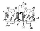
この実施例におけるローレット加工装置は、締付け工具の把持部など円柱状の被加工物1の外周面にローレット模様を形成するもので、外周面に多条溝状のローレット目Aが周設された一対の丸形ダイス2,3と、この両丸形ダイス2,3間に配設された被加工物1の支持台4とで概略構成されており、前記一対の丸形ダイス2,3は、互いの回転軸心2a,3aを同一線上に配置させた態様で平行に配設され、支持台4上に載置した被加工物1の中心を両丸形ダイス2,3の軸心2a,3aと同一線上に配列させた状態で、この丸形ダイス2,3を回転動すると共に、被加工物1方向に押圧動することにより、互いの周面が接触しながら回転動する過程において被加工物1の外周面にローレット加工するもので、ここでは、各丸形ダイス2,3の外周面に多数の斜目条溝によるローレット目Aが周設されており、これにより被加工物1の外周面1aには、網目(あや目とも称される)ローレット模様Bが形成される(図1、図2)。
The knurl processing apparatus in this embodiment forms a knurl pattern on the outer peripheral surface of a
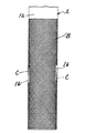
そしてこのローレット加工装置にあっては、被加工物1の外周面1aに、前記のごとくローレット模様Bを形成すると同時に、このローレット模様B域内の所定の個所に、ローレット模様Bがない無模様部1bを設けると共に、この無模様部1bに商標、品番や図柄などCを刻印加工するもので、この実施例では、被加工物1の外周面1aにおける円周上等位置となる2個所に前記刻印加工をするものである。
In the knurling apparatus, the knurled pattern B is formed on the outer peripheral surface 1a of the
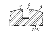
しかして、各丸形ダイス2,3には、被加工物1の円周寸法の2分の1の寸法Dをもって各丸形ダイス2,3の円周を等分割した外周面上の各部位、換言すれば、この丸形ダイス2,3の回転軸心2a,3aを中心として等円弧角度となる外周面上の各部位に、方形の穴5が凹設されており、これにより各丸形ダイス2,3は、ローレット目Aの周設域内に、このローレット目Aが省略された省略部2b,3bが形成される。
Thus, each of the
更にこの丸形ダイス2,3の一方端面には、各穴5方向に有底の挿入孔2c,3cが穿設され、挿入孔2c,3cと各穴5との間にネジ孔2d,3dが設けられており、一方の丸形ダイス2の各穴5には、商標や品番、図柄などの刻印版6が、印面をローレット目A面と同面とした状態で嵌め込まれ、挿入孔2c,3cから挿入した止めネジ7によりネジ孔2d,3dを介して固定されてなるもので(図3、4)、この両丸形ダイス2、3は、加工時にあって各丸形ダイス2,3に凹設された互いの穴5が同回転角度を維持しつつ回転動するように同期回転制御される。
Further, one end face of each of the round dies 2 and 3 is provided with bottomed
そして、支持台4に被加工物1を載置して両丸形ダイス2,3を同期回転動すると共に、被加工物1方向に押圧動することにより、各丸形ダイス2,3に周設されたローレット目Aにより被加工物1の外周面1aにローレット模様B(この例では網目)が形成されると共に、一方の丸形ダイス2の穴5に嵌合固定された刻印版6により、ローレット模様B域内の円周上の2個所に商標、品番や図柄などが刻印されるもので(図5)、この際両丸形ダイス2,3は同期回転されているので、刻印個所は他方の丸形ダイス3の穴5に合致して潰されることなく刻設される。
Then, the
すなわち、直径30mmの被加工物1の外周面1aにおける円周上の等位置となる2個所に、直径120mmの丸形ダイス2,3で刻印加工をする例にあっては、丸形ダイス2,3の回転軸心2a,3aを中心として等円弧角45°となる外周面上の各部位(円弧寸法47.1mm)8個所に方形の穴5を設けることとなる(図1、2)。
That is, in an example in which two round dies 2 and 3 having a diameter of 120 mm are engraved at two positions on the outer circumferential surface 1a of the
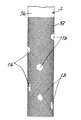
勿論刻印個所数や位置及び刻印形状すなわち丸形ダイス2,3に凹設された穴5の個数、位置、形状は任意であり、また刻印を要しない場合は、各穴5に嵌合固定された刻印版6を取り外すことにより、ローレット目Aが省略された穴5部分(省略部2b,3b)がローレット模様B域内において無模様部1bとして表出され、この穴5(省略部2b,3b)の形状、大きさや配置を考慮することにより、これがローレット模様B域における柄ともなるもので(図7)、これは、穴5を凹設することなく、丸形ダイス2,3に周設されたローレット目Aの所望個所を所望形状に省略(削除)することによっても可能である。
Of course, the number and position of the stamped parts and the stamped shape, that is, the number, position and shape of the
前記のごとくこの実施例のローレット加工装置によれば、ローレット加工時における両丸形ダイス2,3と被加工面1の周面接触回転動にあって、両丸形ダイス2,3の同期回転に伴ない、被加工物1の外周面1a上の所定個所と合致する各丸形ダイス2,3の外周面上の部位に、前記所定個所をローレット模様がない無模様部1bにすることとなると共に、ローレット目を省略(削除)した省略部2a,3aとなる穴5が凹設されており、そしてこの省略部2a,3aである穴5は、商標、商品番号や図柄などの刻印版6が配設可能に構成され、一方の丸形ダイス2の穴5に刻印版6を配設固定して被加工物1を加工するものであるから、被加工物の外周面にローレット模様を形成すると共に、このローレット模様域内に商標などを刻印表示することができるのみか、図柄表示も可能であり、更に刻印版を取外した状態で加工することにより、ローレット模様域内に無模様個所が表出され、これが柄ともなるものであり、しかも所望の形状、大きさ、配置の刻印表示や無模様の形成も可能となるものである。
As described above, according to the knurl processing apparatus of this embodiment, both the round dies 2 and 3 and the
1 被加工物
1a 外周面
1b 無模様部
2,3 丸形ダイス
2a,3a 回転軸心
2b,3b 省略部
2c,3c 挿入孔
2d,3d ネジ孔
4 支持台
5 穴
6 刻印版
7 止めネジ
A ローレット目
B ローレット模様
C 商標,品番,図柄など
DESCRIPTION OF
Claims (4)
前記各丸形ダイスの外周面には、前記被加工物の外周面上の所定個所を前記ローレット模様がない無模様部にすることとなる前記ローレット目の省略部が設けられていると共に、この省略部は、前記無模様部に、商標、商品番号、図柄など刻印表示する取外し可能な刻印板の配設手段を備えており、しかも前記ローレット加工時における両丸形ダイスと被加工物の周面接触回転動にあって、前記被加工物の所定個所と前記各丸形ダイスの無模様部を合致させる、この両丸形ダイスの同期回転制御手段を備えていることを特徴とするローレット模様域内に刻印する装置。 A pair of round dies with multi-grooved knurls on the outer peripheral surface are arranged in parallel with the rotation axis, and a cylindrical workpiece is placed between the round dies. In the knurling apparatus for forming a knurled pattern such as a mesh or a flat pattern on the outer peripheral surface of the workpiece by rotating and pressing the round die in the direction of the workpiece,
On the outer peripheral surface of each of the round dies, there is provided an omission portion of the knurled eye that makes a predetermined portion on the outer peripheral surface of the workpiece a non-patterned portion without the knurled pattern. The abbreviated portion is provided with means for disposing a removable engraving plate on the non-patterned portion, such as a trademark, a product number, and a design, and the round dies and the work piece around the knurl are processed. A knurled pattern comprising a rotary rotation control means for both circular dies, which is in surface contact rotational movement and matches a predetermined portion of the workpiece with a non-patterned portion of each of the circular dies. A device that stamps in the area.
The apparatus for marking in a knurled pattern according to claim 2 or 3, wherein the hole is provided with a fitting / removing fixing means for the stamped plate.
Priority Applications (3)
| Application Number | Priority Date | Filing Date | Title |
|---|---|---|---|
| JP2004113109A JP4744094B2 (en) | 2004-04-07 | 2004-04-07 | A device that displays inscriptions in the knurled pattern area |
| TW93118229A TWI310731B (en) | 2004-04-07 | 2004-06-24 | Device and method for display of marking in the knurled pattern region |
| CNB2004100624105A CN100425390C (en) | 2004-04-07 | 2004-07-02 | Apparatus and method for making pressed marks in zone of knurling patterns |
Applications Claiming Priority (1)
| Application Number | Priority Date | Filing Date | Title |
|---|---|---|---|
| JP2004113109A JP4744094B2 (en) | 2004-04-07 | 2004-04-07 | A device that displays inscriptions in the knurled pattern area |
Publications (2)
| Publication Number | Publication Date |
|---|---|
| JP2005297088A true JP2005297088A (en) | 2005-10-27 |
| JP4744094B2 JP4744094B2 (en) | 2011-08-10 |
Family
ID=35067028
Family Applications (1)
| Application Number | Title | Priority Date | Filing Date |
|---|---|---|---|
| JP2004113109A Expired - Fee Related JP4744094B2 (en) | 2004-04-07 | 2004-04-07 | A device that displays inscriptions in the knurled pattern area |
Country Status (3)
| Country | Link |
|---|---|
| JP (1) | JP4744094B2 (en) |
| CN (1) | CN100425390C (en) |
| TW (1) | TWI310731B (en) |
Cited By (2)
| Publication number | Priority date | Publication date | Assignee | Title |
|---|---|---|---|---|
| JP2009195965A (en) * | 2008-02-25 | 2009-09-03 | Nissan Motor Co Ltd | Apparatus for working fine recessed parts |
| CN103770549A (en) * | 2012-10-25 | 2014-05-07 | 上海万盛保温容器有限公司 | Flat sheet rolling fabrication technology of raised pattern of iron-clad barrel of thermally insulated container |
Family Cites Families (5)
| Publication number | Priority date | Publication date | Assignee | Title |
|---|---|---|---|---|
| CN2094415U (en) * | 1990-11-13 | 1992-01-29 | 航空航天工业部兰州飞控仪器总厂 | Knurling apparatus |
| CN2123397U (en) * | 1992-04-22 | 1992-12-02 | 高航 | Knurling and hobbing machine |
| CN2329462Y (en) * | 1998-02-16 | 1999-07-21 | 洪水龙 | Metal tube embossing machine |
| JP2000084703A (en) * | 1998-09-11 | 2000-03-28 | Koji Ikehara | Die, processing method, and device for knurling process of bar material or pipe material |
| JP4473441B2 (en) * | 2000-11-06 | 2010-06-02 | 克巳 浅野 | Knurling method |
-
2004
- 2004-04-07 JP JP2004113109A patent/JP4744094B2/en not_active Expired - Fee Related
- 2004-06-24 TW TW93118229A patent/TWI310731B/en not_active IP Right Cessation
- 2004-07-02 CN CNB2004100624105A patent/CN100425390C/en not_active Expired - Fee Related
Cited By (2)
| Publication number | Priority date | Publication date | Assignee | Title |
|---|---|---|---|---|
| JP2009195965A (en) * | 2008-02-25 | 2009-09-03 | Nissan Motor Co Ltd | Apparatus for working fine recessed parts |
| CN103770549A (en) * | 2012-10-25 | 2014-05-07 | 上海万盛保温容器有限公司 | Flat sheet rolling fabrication technology of raised pattern of iron-clad barrel of thermally insulated container |
Also Published As
| Publication number | Publication date |
|---|---|
| JP4744094B2 (en) | 2011-08-10 |
| TWI310731B (en) | 2009-06-11 |
| CN100425390C (en) | 2008-10-15 |
| TW200533506A (en) | 2005-10-16 |
| CN1680069A (en) | 2005-10-12 |
Similar Documents
| Publication | Publication Date | Title |
|---|---|---|
| JP2005525937A5 (en) | ||
| JP2013056407A (en) | Pipe marking machine | |
| JP2008030108A (en) | Workpiece support device in laser processing machine | |
| JP4744094B2 (en) | A device that displays inscriptions in the knurled pattern area | |
| US20090078132A1 (en) | Method and apparatus for tool bit marking | |
| CN108569056A (en) | Imprinting apparatus | |
| JPH07144233A (en) | Working device | |
| US6745451B1 (en) | Adapter for machine for manufacturing buttons and method | |
| DK2024149T3 (en) | Apparatus for rotary punching of die cutters with defined geometry and size of a planar structure and its use | |
| JPH0847729A (en) | Method for punching internal circumferential part and external circumferential part | |
| US2386296A (en) | Swaging apparatus | |
| AU2001288138A1 (en) | Method and forming machine for deforming a hollow workpiece | |
| JPH0751227Y2 (en) | Dimensioning stopper | |
| JPH05169787A (en) | Marking device | |
| JPH08276235A (en) | Roll forming device for pin part with roll die | |
| KR20240005463A (en) | Device and method for manufacturing pin for punching of heading machine | |
| JP2706427B2 (en) | Engraving manufacturing equipment | |
| JP2008094065A (en) | Metallic article with knurled cylindrical surface and device for engraving figure/letter on cylindrical surface | |
| KR102592910B1 (en) | Manufacturing method of punching metal cylinder suitable for medium-quantity production | |
| JPH0434947B2 (en) | ||
| JP2846029B2 (en) | Rolling die and processing method using the die | |
| JP6444780B2 (en) | Circular saw waist insertion device and circular saw waist insertion method | |
| JP2007015016A (en) | Method for manufacturing metal plate having cambered hole | |
| US457150A (en) | Art of ornamenting watch-cases | |
| JPH0618657Y2 (en) | Mold equipment |
Legal Events
| Date | Code | Title | Description |
|---|---|---|---|
| A621 | Written request for application examination |
Free format text: JAPANESE INTERMEDIATE CODE: A621 Effective date: 20051130 |
|
| A131 | Notification of reasons for refusal |
Free format text: JAPANESE INTERMEDIATE CODE: A131 Effective date: 20090203 |
|
| A521 | Written amendment |
Free format text: JAPANESE INTERMEDIATE CODE: A523 Effective date: 20090401 |
|
| A02 | Decision of refusal |
Free format text: JAPANESE INTERMEDIATE CODE: A02 Effective date: 20090707 |
|
| A521 | Written amendment |
Free format text: JAPANESE INTERMEDIATE CODE: A523 Effective date: 20101029 |
|
| A01 | Written decision to grant a patent or to grant a registration (utility model) |
Free format text: JAPANESE INTERMEDIATE CODE: A01 |
|
| A61 | First payment of annual fees (during grant procedure) |
Free format text: JAPANESE INTERMEDIATE CODE: A61 Effective date: 20110510 |
|
| FPAY | Renewal fee payment (event date is renewal date of database) |
Free format text: PAYMENT UNTIL: 20140520 Year of fee payment: 3 |
|
| R150 | Certificate of patent or registration of utility model |
Free format text: JAPANESE INTERMEDIATE CODE: R150 Ref document number: 4744094 Country of ref document: JP Free format text: JAPANESE INTERMEDIATE CODE: R150 |
|
| R250 | Receipt of annual fees |
Free format text: JAPANESE INTERMEDIATE CODE: R250 |
|
| R250 | Receipt of annual fees |
Free format text: JAPANESE INTERMEDIATE CODE: R250 |
|
| R250 | Receipt of annual fees |
Free format text: JAPANESE INTERMEDIATE CODE: R250 |
|
| R250 | Receipt of annual fees |
Free format text: JAPANESE INTERMEDIATE CODE: R250 |
|
| R250 | Receipt of annual fees |
Free format text: JAPANESE INTERMEDIATE CODE: R250 |
|
| R250 | Receipt of annual fees |
Free format text: JAPANESE INTERMEDIATE CODE: R250 |
|
| LAPS | Cancellation because of no payment of annual fees |