JP2005297028A - Bending apparatus and its method - Google Patents
Bending apparatus and its method Download PDFInfo
- Publication number
- JP2005297028A JP2005297028A JP2004118481A JP2004118481A JP2005297028A JP 2005297028 A JP2005297028 A JP 2005297028A JP 2004118481 A JP2004118481 A JP 2004118481A JP 2004118481 A JP2004118481 A JP 2004118481A JP 2005297028 A JP2005297028 A JP 2005297028A
- Authority
- JP
- Japan
- Prior art keywords
- die
- bending
- workpiece
- relational expression
- pair
- Prior art date
- Legal status (The legal status is an assumption and is not a legal conclusion. Google has not performed a legal analysis and makes no representation as to the accuracy of the status listed.)
- Pending
Links
- 238000005452 bending Methods 0.000 title claims abstract description 80
- 238000000034 method Methods 0.000 title claims abstract description 27
- 230000009191 jumping Effects 0.000 claims description 13
- 238000003754 machining Methods 0.000 claims description 6
- 238000001514 detection method Methods 0.000 claims description 3
- 238000003825 pressing Methods 0.000 claims description 2
- 238000003672 processing method Methods 0.000 claims 1
- 238000004364 calculation method Methods 0.000 abstract description 8
- 230000037303 wrinkles Effects 0.000 description 9
- 239000012530 fluid Substances 0.000 description 6
- 230000001174 ascending effect Effects 0.000 description 3
- 239000000463 material Substances 0.000 description 2
- 230000007423 decrease Effects 0.000 description 1
- 230000001419 dependent effect Effects 0.000 description 1
- 230000000994 depressogenic effect Effects 0.000 description 1
- 238000010586 diagram Methods 0.000 description 1
- 230000000694 effects Effects 0.000 description 1
- 239000004973 liquid crystal related substance Substances 0.000 description 1
- 239000002184 metal Substances 0.000 description 1
- 230000000630 rising effect Effects 0.000 description 1
- 238000004088 simulation Methods 0.000 description 1
Images


Landscapes
- Bending Of Plates, Rods, And Pipes (AREA)
Abstract
Description
本発明は、曲げ加工の際にワークとダイ間の相対位置変化であるすべりを無くすことにより、該ワークにおけるすべり疵の発生を阻止し、高品質な製品加工を可能とする曲げ加工装置及びその方法に関する。 The present invention provides a bending apparatus capable of preventing high-quality product processing by preventing slippage in the work by eliminating slippage, which is a relative position change between the work and the die during bending. Regarding the method.
従来より、曲げ加工装置としては、例えば実用新登録第3007920号公報に開示されているように、ダイ50(本願の図10)の肩部に回転自在なローラ51が設けられている装置がある。
Conventionally, as a bending apparatus, for example, as disclosed in Japanese Utility Model Registration No. 3007920, there is an apparatus in which a
このローラ51は、曲げ加工時には、ワーク52と線接触し、パンチの下降に伴って、ワーク52が矢印方向に移動すると、該ローラ51も、前記ワーク52と同期して矢印方向に同じ速度で回転するので、該ワーク52とローラ51間には、両者の相対位置変化であるすべりは無く、このため、すべりによる疵はワーク52には発生しないという効果がある。
しかし、前記した従来技術においては、実際には、曲げ加工時に、ワーク52側からの荷重により、該ワーク52とローラ51間には、大きな摩擦力が発生する。
However, in the prior art described above, actually, a large frictional force is generated between the
そのため、ローラ51は、ワーク52と同期して同じ速度で回転することができず、両者間にすべりが発生することにより、該ワーク52には、すべりのために疵が生じてしまう。
Therefore, the
その結果、高品質な製品を加工することはできない。 As a result, high quality products cannot be processed.
本発明の目的は、曲げ加工の際にワークとダイ間の相対位置変化であるすべりを無くすことにより、該ワークにおけるすべり疵の発生を阻止し、高品質な製品加工を可能とする曲げ加工装置及びその方法を提供する。 An object of the present invention is to eliminate a slip which is a relative position change between a workpiece and a die during bending, thereby preventing the occurrence of slip wrinkles in the workpiece and enabling high quality product processing. And a method thereof.
上記課題を解決するために、本発明は、
請求項1に記載したように、各曲げ工程ごとに、加工条件に基づいて、パンチストロークとダイV幅寸法との相対関係式を算出する相対関係式算出手段20Eと、該相対関係式とパンチストローク検出値に基づいて、加工中のダイDのV幅寸法を可変制御するV幅寸法可変制御手段20Gを有することを特徴とする曲げ加工装置、
請求項3に記載したように、
上記請求項1記載の曲げ加工装置を使用する曲げ加工方法であって、
(1)各曲げ工程ごとに、加工条件に基づいて、パンチストロークとダイV幅寸法との相対関係式を算出し、
(2)該相対関係式を算出後、加工中は、パンチストロークを検出し、該パンチストローク検出値と前記相対関係式に基づいて、ダイDのV幅寸法を可変制御することを特徴とする曲げ加工方法、
請求項4に記載したように、固定ダイ14の中央部に、テーパ状の側面部16Bを有するセンタダイ16を上方に付勢した状態で設けると共に、該センタダイ16の両側の固定ダイ14側に、ワークWの跳ね上がり軌跡Kに合致したガイド部14Cを設け、該センタダイ16のテーパ状側面部16Cと固定ダイ14のガイド部14C間に、ワークWの跳ね上がり軌跡Kに合致した形状の一対の移動ダイ15A、15Bを挟持し、ワークWに押圧されたセンタダイ16の下降に伴って、前記一対の移動ダイ15A、15Bが該ワークWに当接した状態で上昇しながら旋回可能としたことを特徴とする曲げ加工装置、及び
請求項6に記載したように、
上記請求項4記載の曲げ加工装置を使用する曲げ加工方法であって、
(1)センタダイ16と一対の移動ダイ15A、15Bと固定ダイ14上に、ワークWを載せ、
(2)その後、該ワークWでセンタダイ16を押圧することにより、該センタダイ16を下降させ、
(3)該下降するセンタダイ16により、一対の移動ダイ15A、15Bを押し上げ、
(4)該一対の移動ダイ15A、15Bを、固定ダイ14側のガイド部14Cに沿ってワークWに当接した状態で上昇させながら旋回させることを特徴とする曲げ加工方法という技術的手段を講じている。
In order to solve the above problems, the present invention provides:
The relative relational expression calculating means 20E for calculating the relative relational expression between the punch stroke and the die V width dimension on the basis of the machining conditions for each bending step, and the relative relational expression and the punch A bending apparatus characterized by having V width dimension variable control means 20G for variably controlling the V width dimension of the die D being processed based on the stroke detection value;
As described in
A bending method using the bending apparatus according to
(1) For each bending step, a relative relational expression between the punch stroke and the die V width dimension is calculated based on the processing conditions,
(2) After calculating the relative relational expression, a punch stroke is detected during processing, and the V width dimension of the die D is variably controlled based on the detected punch stroke value and the relative relational expression. Bending method,
As described in
A bending method using the bending apparatus according to
(1) Place the workpiece W on the
(2) Thereafter, the center die 16 is lowered by pressing the center die 16 with the workpiece W,
(3) A pair of moving
(4) A technical means called a bending method, characterized in that the pair of
上記本発明の構成によれば、例えばワークWの実際の挙動(図2)を元に算出された相対関係式(図3)に基づき、加工中には、この相対関係式と検出したパンチストロークにより、一対の旋回ダイ5A、5Bを旋回させることができるので、加工中のワークWに追従して、ダイDのV幅の可変制御が可能となり、それにより、曲げ加工の際にワークとダイ間のすべりが無くなり、すべり疵の発生が阻止される。 According to the configuration of the present invention described above, for example, based on the relative relational expression (FIG. 3) calculated based on the actual behavior of the workpiece W (FIG. 2), this relative relational expression and the detected punch stroke are processed during machining. Thus, the pair of swiveling dies 5A and 5B can be swung, so that the V width of the die D can be variably controlled following the work W being processed. There is no slip in between, and the occurrence of slip wrinkles is prevented.
従って、本発明によれば、曲げ加工の際にワークとダイ間の相対位置変化であるすべりを無くすことにより、該ワークにおけるすべり疵の発生を阻止し、高品質な製品加工を可能とする曲げ加工装置及びその方法を提供することができる。 Therefore, according to the present invention, by eliminating the slip that is the relative position change between the workpiece and the die during the bending process, the generation of a slip wrinkle in the workpiece is prevented, and the bending that enables high-quality product processing. A processing apparatus and method thereof can be provided.
以下、本発明を、実施例により添付図面を参照して、説明する。
図1は本発明の全体図である。
Hereinafter, the present invention will be described by way of example with reference to the accompanying drawings.
FIG. 1 is an overall view of the present invention.
図1に示す曲げ加工装置は、例えば上部テーブル1をラムとする下降式のプレスブレーキである。 The bending apparatus shown in FIG. 1 is a descending press brake having an upper table 1 as a ram, for example.
このプレスブレーキは、機械本体の両側に側板30を有し、該側板30の上下部に取り付けられた上部テーブル1と下部テーブル2を有し、該上下テーブル1、2には、金型を構成するパンチPとダイDが装着され、該パンチPとダイDの協働によりワークWを曲げ加工するようになっている。
This press brake has
上記ダイDは、その上のワークWとの間にすべりを無くし、すべり疵の発生を阻止するように、V幅が可変となっている。 The die D has a variable V width so that no slip occurs between the die D and the workpiece W on the die D, and the occurrence of slip wrinkles is prevented.
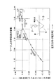
即ち、図2は、ダイD上にワークWを載せた状態で、パンチPが下降し該ワークWに接触したときからの(ピンチングポイント)、該ワークW上であってダイDのV溝中心Cに関して右側の或る特定点の挙動を示す図である。 That is, FIG. 2 shows a state where the punch P descends and comes into contact with the workpiece W with the workpiece W placed on the die D (pinching point). 6 is a diagram illustrating the behavior of a certain point on the right side with respect to C. FIG.
図示するように、特定点は、加工開始から初期の間は、V溝から遠ざかる方向(右方向)に移動し(図2の○印、(1)→(2))、その後、V溝に近付く方向(左方向)へ移動し(図2の●印、(3))、更に、V溝に沿ってV溝下方へ引き込まれるように移動する(図2の●印、(4)→(5))。 As shown in the drawing, the specific point moves in the direction away from the V groove (right direction) during the initial period from the start of machining (marked with a circle in FIG. 2, (1) → (2)), and then into the V groove. It moves in the approaching direction (left direction) (● mark in FIG. 2, (3)), and further moves so as to be drawn downward along the V groove (● mark in FIG. 2, (4) → ( 5)).
本発明は、このような曲げ加工時における、ワークW上の特定点の挙動に着眼し、該特定点の左右方向(V幅方向)の動きに追従するように、ダイDのV幅を移動制御することにより、ワークWとダイDとの相対位置変化(すべり)を無くすこととした。 The present invention focuses on the behavior of a specific point on the workpiece W during such bending, and moves the V width of the die D so as to follow the movement of the specific point in the horizontal direction (V width direction). By controlling, the relative position change (slip) between the workpiece W and the die D was eliminated.
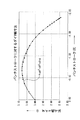
そのために、パンチストロークを独立変数(X)とし、該パンチストロークに対するダイV幅寸法を従属変数(Y)とする両者の相対関係式を算出する(図3)。 For this purpose, a relative relational expression is calculated with the punch stroke as an independent variable (X) and the die V width dimension with respect to the punch stroke as a dependent variable (Y) (FIG. 3).
上記相対関係式を、例えば次式で表す。
Y=aX3 +bX 2+cX+d・・・・(1)
The relative relational expression is represented by the following expression, for example.
Y = aX 3 + bX 2 + cX + d (1)
上記(1)式において、各係数a、b、c、dは、加工条件(ワークWの材質、ダイDのV幅、ダイDの肩部アール、パンチPの先端アール)により異なる。 In the above equation (1), the coefficients a, b, c, and d differ depending on the processing conditions (the material of the workpiece W, the V width of the die D, the shoulder radius of the die D, and the tip radius of the punch P).
具体的には、曲げ工程ごとに、加工条件に基づいて、上記(1)式の各係数a、b、c、dが決定され、それにより、この相対関係式が加工前のシミュレーションにより算出される(図6のステップ103)。
Specifically, for each bending step, the coefficients a, b, c, and d in the above equation (1) are determined based on the processing conditions, and this relative relational expression is calculated by a simulation before processing. (
この相対関係式を算出後は、ラム1を下降することにより(図6のステップ104)、曲げ加工を開始してから、ラム(パンチ)ストロークを、既存のラム位置検出手段6(図1)(例えばリニアスケール、エンコーダなど)により検出し(図6のステップ105)、ピンチングポイント後は、該検出値と前記相対関係式に基づいて、ダイDのV幅を調整することにより(図6のステップ106)、ワークWとダイD間のすべりを無くし、すべり疵の発生を阻止する。
After calculating the relative relational expression, the
図4、図5は、ダイDのV幅調整機構の例を示す。 4 and 5 show examples of the V width adjusting mechanism of the die D. FIG.
図4において、下部テーブル2上には、U字型のダイホルダ4を介して、一対のダイ5A、5Bが旋回自在に設けられている。
In FIG. 4, a pair of
上記旋回ダイ5A、5Bは、L字型のアームにより構成され、前記ダイホルダ4の軸受け9に回転自在に支承された共通の軸8に対して、ヒンジ結合している。
The turning
また、上記旋回ダイ5A、5Bには、前記ダイホルダ4側に設けられた2つ宛のアクチュエータ10A、10B及び11A、11B(例えば流体シリンダ、圧電素子、モータ・ボールねじ・ナット機構など)がそれぞれ結合している。
The swiveling dies 5A and 5B are provided with two
この構成により、後述するNC装置20(図1)のV幅寸法可変制御手段20Gを介して前記アクチュエータ10A(図4)、10B及び11A、11Bを作動すれば、旋回ダイ5A、5Bが旋回することにより、V幅を調整することができる。
With this configuration, when the
例えば、アクチュエータ10A、10B及び11A、11Bが流体シリンダの場合には、上部流体シリンダ10A、11Aのピストンロッドを引き込み、下部流体シリンダ10B、11Bのピストンロッドを押し出せば、右側ダイ5Aが時計方向に、左側ダイ5Bが反時計方向にそれぞれ旋回することにより、V幅を拡大することができる。
For example, when the
また、例えば、前記の場合に、上部流体シリンダ10A、11Aのピストンロッドを押し出し、下部流体シリンダ10B、11Bのピストンロッドを引き込めば、右側ダイ5Aが反時計方向に、左側ダイ5Bが時計方向にそれぞれ旋回することにより、V幅を縮小することができる。
Further, for example, in the above case, if the piston rods of the
図5は、ダイDのV幅調整機構の他の例を示し、図4と異なるのは、旋回ダイ5A、5BがS字型であり、該S字型旋回ダイ5A、5Bの下端に、1つ宛のアクチュエータ12、13が結合している点である。
FIG. 5 shows another example of the V width adjusting mechanism of the die D. The difference from FIG. 4 is that the turning dies 5A and 5B are S-shaped, and the lower ends of the S-shaped turning dies 5A and 5B are That is, the
この構成により、同様にV幅寸法可変制御手段20G(図1)を介して前記アクチュエータ12(図5)、13を作動すれば、各旋回ダイ5A、5Bが旋回することにより、V幅を調整することができる。 With this configuration, if the actuators 12 (FIG. 5) and 13 are similarly operated via the V width dimension variable control means 20G (FIG. 1), the turning dies 5A and 5B are turned to adjust the V width. can do.
例えば、アクチュエータ12、13がモータ・ボールねじ・ナット機構で構成され、各ナット12A、13Aに旋回ダイ5B、5Aがヒンジ結合しているものとする。
For example, it is assumed that the
この場合には、ボールねじ12B、13Bを回転して、ナット12A、13Aを離反させれば、ダイ5Aが時計方向に、ダイ5Bが反時計方向にそれぞれ旋回することにより、V幅を拡大することができる。
In this case, if the ball screws 12B and 13B are rotated to separate the nuts 12A and 13A, the
また、例えば、前記の場合に、ボールねじ12B、13Bを回転して、ナット12A、13Aを接近させれば、ダイ5Aが反時計方向に、ダイ5Bが時計方向それぞれ旋回することにより、V幅を縮小することができる。
Also, for example, in the above case, if the ball screws 12B and 13B are rotated to bring the nuts 12A and 13A closer, the
このような構成を有するプレスブレーキのNC装置20は(図1)、CPU20Aと、入出力手段20Bと、記憶手段20Cと、曲げ順等算出手段20Dと、相対関係式算出手段20Eと、ラム駆動制御手段20Fと、V幅寸法可変制御手段20Gにより構成されている。
The press
CPU20Aは、本発明を実施するための動作手順(例えば図6に相当)に従って、曲げ順等算出手段20D、相対関係式算出手段20Eなど図1に示す装置全体を統括制御する。
The
入出力手段20Bは、例えば前記上部テーブル1に設けられた操作盤(図示省略)であって、キーボードなどの入力手段と液晶画面などの出力手段で構成され、加工対象であるワークWの製品情報、例えばCAD情報を入力し、その結果は画面で確認できるようになっている。 The input / output means 20B is, for example, an operation panel (not shown) provided on the upper table 1, and includes input means such as a keyboard and output means such as a liquid crystal screen, and product information of the workpiece W to be processed. For example, CAD information is input, and the result can be confirmed on the screen.
この場合、CAD情報は、ワークの曲げ角度、曲げ長さ、板厚、材質、フランジ高さなど、また、ワークの展開図、立体姿図などにより構成されている。 In this case, the CAD information is composed of a workpiece bending angle, bending length, plate thickness, material, flange height, and the like, as well as a development view and a three-dimensional view of the workpiece.
記憶手段24Cは、例えば前記入出力手段20Bを介して入力されたCAD情報を記憶しておき、また、相対関係式算出手段20Eが算出した相対関係式(図3)を記憶しておく。
The storage unit 24C stores, for example, CAD information input through the input /
曲げ順等算出手段20Dは(図1)、前記入出力手段24Bを介して入力された製品情報に基づいて、曲げ順を算出すると共に、曲げ工程ごとに使用される金型P、D(金型レイアウトを含む)、更には、D値、L値などを算出する。 The bending order calculation means 20D (FIG. 1) calculates the bending order based on the product information input via the input / output means 24B, and uses the molds P and D (metal molds) used for each bending process. In addition, a D value, an L value, and the like are calculated.
相対関係式算出手段20Eは、各曲げ工程ごとに、加工条件に基づいて、前記した(1)式の各係数を決定することにより、相対関係式を算出する。 The relative relational expression calculating means 20E calculates the relative relational expression by determining each coefficient of the above-described formula (1) based on the machining conditions for each bending step.
ラム駆動制御手段20Fは(図1)、前記相対関係式算出手段20Eを介して相対関係式を算出した後(図6のステップ103)、例えば作業者がダイD上にワークWを戴置して突当(図示省略)に突き当て、フットペダル(図示省略)を踏んだときに、ラム駆動源3(図1)を作動させ、ラム1を下降させる(図6のステップ104)。
The ram drive control means 20F (FIG. 1) calculates the relative relational expression via the relative relational expression calculation means 20E (
V幅寸法可変制御手段20Gは(図1)、パンチPがワークWに接触した後(ピンチングポイント後)、リニアスケール6を介して検出したラムストローク検出値と前記相対関係式に基づいて、ダイDのV幅を調整する(図6のステップ105→ステップ106)。
The V width dimension variable control means 20G (FIG. 1) is based on the ram stroke detection value detected via the
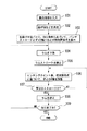
以下、上記構成を有する本発明の動作を図6に基づいて説明する。
A.相対関係式を算出するまでの動作。
図6のステップ101において、製品情報を入力し、ステップ102において、曲げ順などを算出し、ステップ103において、各曲げ工程ごとに、加工条件に基づいて、パンチストロークとダイV幅寸法との相対関係式を算出する。
The operation of the present invention having the above configuration will be described below with reference to FIG.
A. The operation until the relative relational expression is calculated.
In
即ち、入出力手段24B(図1)を介して製品情報が入力されると、CPU24Aは、曲げ順等算出手段20Dと、相対関係式算出手段20Eを制御し、曲げ順を算出させると共に、曲げ工程ごとの金型、D値、L値などを算出させ、更には、曲げ工程ごとに、加工条件に基づいて、前記(1)式における各係数を決定することにより、相対関係式を算出させる。 That is, when product information is input via the input / output means 24B (FIG. 1), the CPU 24A controls the bending order calculation means 20D and the relative relational expression calculation means 20E to calculate the bending order and the bending order. A die, D value, L value, etc. for each process are calculated, and further, a relative relational expression is calculated for each bending process by determining each coefficient in the equation (1) based on the processing conditions. .
その後、CPU24Aは、記憶手段24Cを制御し、前記算出された相対関係式を予め記憶させる。 Thereafter, the CPU 24A controls the storage unit 24C to store the calculated relative relational expression in advance.
B.曲げ加工動作。
図6のステップ104において、ラム1を下降させ、ステップ105において、ラムストロークを検出し、ステップ106において、ピンチングポイント後、相対関係式に基づいて、ダイDのV幅を調整する
B. Bending operation.
In
即ち、前記ステップ103において、相対関係式が算出されたことを検知したCPU24Aは(図1)、ラム駆動制御手段20Fを介してラム1を下降させ、ラム1下降後は、リニアスケール6を介してラム(パンチ)ストロークを検出させ、これにより、ピンチングポイント後は、V幅寸法可変制御手段20Gを介して、上記ラム(パンチ)ストロークの該検出値と前記相対関係式に基づいて、ダイDのV幅を調整させる。
That is, in
これにより、本発明によれば、既述したように、ワークWとダイD間のすべりを無くし、すべり疵の発生を阻止する。 As a result, according to the present invention, as described above, the slip between the workpiece W and the die D is eliminated, and the occurrence of slip wrinkles is prevented.
このV幅の調整は、ラム1が所定のストロークに到達するまで行われ(図6のステップ107のNO)、所定のストロークに到達後は(図6のステップ107のYES)、CPU24Aは(図1)、ラム駆動制御手段20Fを介してラム1を停止させ、例えば最初の曲げ工程の加工は終了する。
The adjustment of the V width is performed until the
更に、加工を継続する場合には(図6のステップ109のNO)、前記ステップ104に戻って同じ動作を繰り返し、全ての曲げ工程について前記ステップ104〜ステップ108の動作が終わったときに、全加工が完了し(図6のステップ109のYES)、動作は停止する。
Further, when processing is continued (NO in
既述した第1実施例においては、ワークWの曲げ角度における最終ストロークは、金型の初期V幅を元に算出しているが、本発明では、前記したように、ピンチングポイント後のラム1の下降に従ってダイDのV幅が連続的に変化するので、加工中の角度をリアルタイムに検出できる曲げ角度センサを設置することにより、曲げ角度を直接に検出することが、角度精度を向上させるためには好ましい。
In the first embodiment described above, the final stroke at the bending angle of the workpiece W is calculated based on the initial V width of the mold, but in the present invention, as described above, the
例えば、既存の曲げ角度センサ29を(図1)(特開2000−51951に開示)、ダイD近傍に設置し、ワークWの曲げ角度が、スプリングバック(ほぼ1°)を考慮した目標角度89°になった時点でラム1のストロークを終了させる(このようにすれば、曲げ角度に対するストロークを算出する必要はない)。
For example, an existing bending angle sensor 29 (FIG. 1) (disclosed in Japanese Patent Laid-Open No. 2000-51951) is installed in the vicinity of the die D, and the bending angle of the workpiece W is a target angle 89 considering spring back (approximately 1 °). The stroke of the
図7〜図9は、本発明の第2実施例を示す図であり、前記第1実施例(図2〜図6)とは、ワークWとダイD間のすべりを無くし、すべり疵の発生を阻止する点では、共通するが、アクチュエータを設けることなく、ピンチングポイント後のワークWの跳ね上がり軌跡K(図7)に追従すべく、固定ダイ14(図8)の両側に一対の移動ダイ15A、15Bを設けると共に、中央部には、ばね付勢されたセンタダイ16を設けた点が異なる。
7 to 9 are views showing a second embodiment of the present invention. The first embodiment (FIGS. 2 to 6) is different from the first embodiment (FIGS. 2 to 6) in that the slip between the workpiece W and the die D is eliminated, and the occurrence of slip wrinkles occurs. In common, the pair of moving dies 15A are provided on both sides of the fixed die 14 (FIG. 8) so as to follow the jumping locus K (FIG. 7) of the workpiece W after the pinching point without providing an actuator. 15B, and a
即ち、図7は、ダイD上にワークWを載せた状態で、パンチPが下降し該ワークWに接触したときからの(ピンチングポイント)、ダイDのV溝中心Cに関して右側における該ワークW端部の跳ね上がり軌跡Kを示す図である。 That is, FIG. 7 shows the state of the workpiece W on the right side with respect to the center C of the V groove of the die D after the punch P descends and contacts the workpiece W with the workpiece W placed on the die D (pinching point). It is a figure which shows the jump locus | trajectory K of an edge part.
図示するように、ワークW端部は、曲げ加工の進行と共に、円弧状の軌跡Kを描きながら上方に跳ね上がっている。 As shown in the drawing, the end portion of the workpiece W jumps upward while drawing an arc-shaped locus K as the bending process proceeds.
本発明は、このような曲げ加工時における、ワークW端部の跳ね上がり軌跡Kに着眼し、該跳ね上がり軌跡Kに合致した旋回しながら上昇する移動ダイ15A、15Bを設けることにより、ワークWとダイDとの相対位置変化(すべり)を無くすこととした。 The present invention focuses on the jumping locus K at the end of the workpiece W at the time of such bending, and by providing the moving dies 15A and 15B that rise while turning in accordance with the rising locus K, the workpiece W and the die are provided. The relative position change (slip) with D was eliminated.
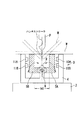
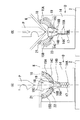
図8は、ダイ構造の例を示し、下部テーブル2上には、固定ダイ14を介して、前記した一対の移動ダイ15A、15Bと、中央部のセンタダイ16がそれぞれ設けられている。
FIG. 8 shows an example of the die structure. On the lower table 2, the pair of moving dies 15 </ b> A and 15 </ b> B and the center die 16 at the center are provided via the fixed
上記固定ダイ14(図8(A))の中央部には、垂直状空洞部14Aとテーパ状空洞部14Bが連続して形成され、曲げ加工の進行と共に(図8(B))下降するセンタダイ16の垂直状側面部16Aとテーパ状側面部16Bが、それぞれ前記空洞部14Aと14Bに進入するようになっている。
A
また、固定ダイ14側の上記テーパ状空洞部14Bに連続して形成された上方の空洞部は、一対の移動ダイ15A、15Bを案内する円弧状のガイド部14Cとなっている。
The upper cavity formed continuously with the
前記固定ダイ14の垂直状空洞部14Aの底面には、弾性部材17、例えばコイルばねの下端が当接し、該コイルばね17の上端には、既述したセンタダイ16の下端が当接することにより、該センタダイ16が上方に付勢されている。
An
この構成により、センタダイ16の上面と、固定ダイ14の上面と、後述する一対の移動ダイ15A、15Bの上面とは、同一水平面上に配置され、図8(A)に示すように、各上面上に加工前にワークWを載せて突当(図示省略)に突き当て該ワークWを位置決めすることができる。
With this configuration, the upper surface of the center die 16, the upper surface of the fixed
上記センタダイ16は(図8(A))、間隔が最も小さい両側の垂直状側面部16Aと、該垂直状側面部16Aに連続して間隔が徐々に大きくなっている両側のテーパ状側面部16Bと、該テーパ状側面部16Bに連続して間隔が最も大きい両側の垂直状側面部16Cにより構成され、全体としてほぼT字型に形成されている。
The center die 16 (FIG. 8 (A)) includes a vertical
このセンタダイ16と、前記固定ダイ14のガイド部14C間には、図示するように、一対の移動ダイ15A、15Bが挟持されている。 A pair of movable dies 15A and 15B are sandwiched between the center die 16 and the guide portion 14C of the fixed die 14 as shown in the figure.
上記一対の移動ダイ15A、15Bは、前記した円弧状のワークW跳ね上がり軌跡K(図7)に合致した形状を有し、例えば右側の移動ダイ15Aは、該跳ね上がり軌跡Kとほぼ同じ円弧形状を有している。 The pair of moving dies 15A and 15B has a shape that matches the arc-shaped workpiece W jumping locus K (FIG. 7). For example, the right moving die 15A has an arc shape that is substantially the same as the jumping locus K. Have.
これにより、ピンチングポイント後(図8(B))、パンチPによりワークWが曲げられて該ワークWが跳ね上がっても、一対の移動ダイ15A、15Bは、その上端側が、該跳ね上がるワークWの下面に追従して上昇しながら旋回する。 Thus, even after the pinching point (FIG. 8B), even if the workpiece W is bent by the punch P and the workpiece W jumps up, the pair of moving dies 15A and 15B has the upper end side of the lower surface of the workpiece W jumping up. Turn while following up.
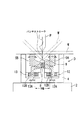
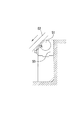
更に,一対の移動ダイ15A、15Bのそれぞれの上端と下端には、当接部材18と19、21と22が設けられており、該一対の移動ダイ15A、15BのワークWとセンタダイ16に対する追従動作が円滑に行われると共に、該ワークWとセンタダイ16に対する線接触状態が保持されるようになっている。
Furthermore,
例えば、右側の移動ダイ15Aに関して説明すれば、図9に示すように、上端と下端には、全体として樋状の形状を有し、横断面形状が半円形の当接部材18と19が、例えば回転自在に設けられている。
For example, with respect to the right moving die 15A, as shown in FIG. 9, the
この構成により、曲げ加工の進行と共に(図8(A)→図8(B))、前記一対の移動ダイ15A、15Bは、上端がワークWの下面、下端がセンタダイ16のテーパ状側面部16Bと垂直状側面部16Cに対する線接触状態を常に保持できるようになり、特に曲げ加工の際のワークWとダイD間の相対位置変化であるすべりが、より一層無くなる。
With this configuration, as the bending process proceeds (FIG. 8 (A) → FIG. 8 (B)), the pair of moving dies 15A and 15B has an upper end on the lower surface of the workpiece W and a lower end on the tapered
以下、前記構成を有する本発明の動作を図8に基づいて説明する。 The operation of the present invention having the above configuration will be described below with reference to FIG.
先ず、図8(A)に示すように、上方に付勢されたセンタダイ16と、該センタダイ16と固定ダイ14間に挟持された移動ダイ15A、15B、及び固定ダイ14の上に、図示するように、ワークWを載せて位置決めする。
First, as shown in FIG. 8A, the center die 16 biased upward, the moving dies 15A and 15B sandwiched between the center die 16 and the fixed
このときには、前記移動ダイ15A、15Bは、その上端がワークWの下面に、下端がセンタダイ16のテーパ状側面部16Bにそれぞれ当接している。
At this time, the upper ends of the moving dies 15A and 15B are in contact with the lower surface of the workpiece W and the lower ends thereof are in contact with the tapered
また、この場合、前記した上端の当接部材18と21、下端の当接部材19と22が、それぞれ向きを変えることにより、前者がワークWの下面と、後者がセンタダイ16のテーパ状側面部16Bとに線接触している。
Further, in this case, the upper
この状態で、図8(B)に示すように、パンチPを下降させワークWと接触させることにより(ピンチングポイント)曲げ加工が開始され、図示するように、該ワークWは跳ね上がる。 In this state, as shown in FIG. 8B, bending is started by lowering the punch P and bringing it into contact with the workpiece W (pinching point), and the workpiece W jumps up as shown.
そのとき、パンチPに押圧されたワークWの下面中央が、センタダイ16を押圧するので、該センタダイ16は、コイルばね17の復元力Fに抗して下降する。
At this time, the center of the lower surface of the work W pressed by the punch P presses the center die 16, and the center die 16 descends against the restoring force F of the
これにより、下降するセンタダイ16のテーパ状側面部16Bが(図8(A))それに当接している移動ダイ15A、15Bの下端を押し上げるので、該移動ダイ15A、15Bは、円弧状のガイド部14Cに沿って上昇しながら旋回運動を開始する。
Thereby, the taper-shaped
既述したように、移動ダイ15A、15Bは、ワークW跳ね上がり軌跡Kの(図7)円弧に対応しているので、ワークWが跳ね上がっても、該跳ね上がり軌跡Kに合致した上昇旋回運動を継続し、その間、移動ダイ15A、15Bの上端の当接部材18と21は、それぞれ向きを変えることにより、跳ね上がるワークWの下面と線接触し、また、下端の当接部材19と22も、それぞれ向きを変えることにより、センタダイ16のテーパ状側面部16B、更にはその上の垂直状側面部16Cと線接触している。
As described above, since the moving dies 15A and 15B correspond to the arc of the workpiece W jumping locus K (FIG. 7), even if the workpiece W jumps up, the ascending turning motion that matches the jumping locus K is continued. In the meantime, the
このようにして曲げ加工が進行し、ワークW下面中央で押圧されたセンタダイ16が下降を継続すると、そのテーパ状側面部16Bと垂直状側面部16Aも下降して固定ダイ14側のテーパ状空洞部14B(図8(B))と垂直状空洞部14Aに進入する。
When the bending process proceeds in this way and the center die 16 pressed at the center of the lower surface of the workpiece W continues to descend, the tapered
そして、センタダイ16が、完全に固定ダイ14側のテーパ状空洞部14Bと垂直状空洞部14Aに進入した時点で、パンチPが、所定のストロークを終了して曲げ加工は完了し、この時点で、該センタダイ16の上の垂直状側面部16Cに、一対の移動ダイ15A、15Bの下端が当接し、跳ね上がったワークWの下面には、該一対の移動ダイ15A、15Bの上端が当接している。
When the center die 16 completely enters the tapered
上記したように、本発明によれば、ワークWの跳ね上がり軌跡Kに合致して上昇旋回運動可能な一対の移動ダイ15A、15Bを設けたことにより、同様に、曲げ加工の際にワークWとダイD間の相対位置変化であるすべりを無くすことにより、該ワークにおけるすべり疵の発生を阻止し、高品質な製品加工を可能とすることができる。 As described above, according to the present invention, by providing the pair of moving dies 15A and 15B that can move up and turn in accordance with the jumping locus K of the workpiece W, similarly, the workpiece W and the workpiece W are bent during bending. By eliminating the slip, which is a relative position change between the dies D, it is possible to prevent the occurrence of slip wrinkles in the workpiece and enable high-quality product processing.
本発明は、曲げ加工の際にワークとダイ間の相対位置変化であるすべりを無くすことにより、該ワークにおけるすべり疵の発生を阻止し、高品質な製品加工を可能とする曲げ加工装置及びその方法に利用可能であり、具体的には、下降式プレスブレーキのみならず上昇式プレスブレーキにも利用可能であり、更には、ワーク上の特定点の挙動に追従してV幅を可変制御するダイにも、また、ワーク端部の跳ね上がり軌跡に合致して上昇旋回可能な移動ダイにも利用可能である。 The present invention provides a bending apparatus capable of preventing high-quality product processing by preventing slippage in the work by eliminating slippage, which is a relative position change between the work and the die during bending. It can be used for a method, specifically, it can be used not only for a descending press brake but also for an ascending press brake. Further, the V width is variably controlled following the behavior of a specific point on the workpiece. The present invention can also be used for a die and a movable die that can turn up and down in accordance with a jumping locus of a workpiece end.
1 上部テーブル
2 下部テーブル
3 ラム1の駆動源
4 ダイホルダ
5A 5B ダイ片
6 リニアスケール
8 軸
9 軸受け
10A、10B、11A、11B、12、13 アクチュエータ
14 固定ダイ
15A、15B 移動ダイ
16 センタダイ
17 コイルばね
18、19、21、22 当接部材
20 NC装置
20A CPU
20B 入出力手段
20C 記憶手段
20D 曲げ順等算出手段
20E 相対関係式算出手段
20F ラム駆動制御手段
20G V幅寸法可変制御手段
29 曲げ角度センサ
30 側板
D ダイ
P パンチ
W ワーク
DESCRIPTION OF
20B Input / output means 20C Storage means 20D Bending order etc. calculating means 20E Relative relational expression calculating means 20F Ram drive control means 20G V width dimension variable control means 29
Claims (6)
該相対関係式とパンチストローク検出値に基づいて、加工中のダイのV幅寸法を可変制御するV幅寸法可変制御手段を有することを特徴とする曲げ加工装置。 A relative relational expression calculating means for calculating a relative relational expression between the punch stroke and the die V width dimension on the basis of the processing conditions for each bending step;
A bending apparatus comprising: a V width dimension variable control means for variably controlling a V width dimension of a die being processed based on the relative relational expression and a punch stroke detection value.
(1)各曲げ工程ごとに、加工条件に基づいて、パンチストロークとダイV幅寸法との相対関係式を算出し、
(2)該相対関係式を算出後、加工中は、パンチストロークを検出し、該パンチストローク検出値と前記相対関係式に基づいて、ダイのV幅寸法を可変制御することを特徴とする曲げ加工方法。 A bending method using the bending apparatus according to claim 1,
(1) For each bending step, a relative relational expression between the punch stroke and the die V width dimension is calculated based on the processing conditions,
(2) After calculating the relative relational expression, a punch stroke is detected during machining, and the V width dimension of the die is variably controlled based on the detected punch stroke value and the relative relational expression. Processing method.
(1)センタダイと一対の移動ダイと固定ダイ上に、ワークWを載せ、
(2)その後、該ワークでセンタダイを押圧することにより、該センタダイを下降させ、
(3)該下降するセンタダイにより、一対の移動ダイを押し上げ、
(4)該一対の移動ダイを、固定ダイ側のガイド部に沿ってワークに当接した状態で上昇させながら旋回させることを特徴とする曲げ加工方法。 A bending method using the bending apparatus according to claim 4,
(1) Place the workpiece W on the center die, the pair of moving dies and the fixed die,
(2) Then, the center die is lowered by pressing the center die with the workpiece,
(3) A pair of moving dies are pushed up by the descending center die,
(4) A bending method characterized in that the pair of moving dies are swung while being raised in a state of being in contact with the work along the guide portion on the fixed die side.
Priority Applications (1)
| Application Number | Priority Date | Filing Date | Title |
|---|---|---|---|
| JP2004118481A JP2005297028A (en) | 2004-04-14 | 2004-04-14 | Bending apparatus and its method |
Applications Claiming Priority (1)
| Application Number | Priority Date | Filing Date | Title |
|---|---|---|---|
| JP2004118481A JP2005297028A (en) | 2004-04-14 | 2004-04-14 | Bending apparatus and its method |
Publications (1)
| Publication Number | Publication Date |
|---|---|
| JP2005297028A true JP2005297028A (en) | 2005-10-27 |
Family
ID=35329205
Family Applications (1)
| Application Number | Title | Priority Date | Filing Date |
|---|---|---|---|
| JP2004118481A Pending JP2005297028A (en) | 2004-04-14 | 2004-04-14 | Bending apparatus and its method |
Country Status (1)
| Country | Link |
|---|---|
| JP (1) | JP2005297028A (en) |
Cited By (2)
| Publication number | Priority date | Publication date | Assignee | Title |
|---|---|---|---|---|
| KR101036007B1 (en) | 2008-12-08 | 2011-05-23 | 김재문 | Multifunction Bending Machine and Multifunction Bending Die Assembly |
| JP2019531194A (en) * | 2016-10-21 | 2019-10-31 | ロッレリ・ソチエタ・ペル・アツィオーニROLLERI S.p.A. | Adjustable die for press brake |
-
2004
- 2004-04-14 JP JP2004118481A patent/JP2005297028A/en active Pending
Cited By (3)
| Publication number | Priority date | Publication date | Assignee | Title |
|---|---|---|---|---|
| KR101036007B1 (en) | 2008-12-08 | 2011-05-23 | 김재문 | Multifunction Bending Machine and Multifunction Bending Die Assembly |
| JP2019531194A (en) * | 2016-10-21 | 2019-10-31 | ロッレリ・ソチエタ・ペル・アツィオーニROLLERI S.p.A. | Adjustable die for press brake |
| JP7092379B2 (en) | 2016-10-21 | 2022-06-28 | ロッレリ・ソチエタ・ペル・アツィオーニ | Adjustable die for press brake |
Similar Documents
| Publication | Publication Date | Title |
|---|---|---|
| CN1181332C (en) | Thin plate forming method and device with variable blank holder force and variable stamping speed | |
| CN104128396B (en) | Workpiece straightener and aligning method thereof | |
| JP2006007296A (en) | Device for controlling press-forging machine by servomotor | |
| CN204018439U (en) | A kind of shell shaper of R bending structure | |
| JP6868248B2 (en) | How to set transfer parameters for the strip-shaped work transfer device and the strip-shaped work transfer device of the press machine | |
| KR102495176B1 (en) | Incremental forming apparatus | |
| JP2003311496A (en) | Die height adjustment device for press machine | |
| WO2001003864A1 (en) | Sheet metal bending system comprising press brake and sheet metal support device, control data creating method therefor, and computer-readable storage medium where the control data is stored | |
| JP2005297028A (en) | Bending apparatus and its method | |
| JP2010162558A (en) | Bending machine | |
| JP6401620B2 (en) | Bending method, back gauge device, and press brake | |
| JP4865489B2 (en) | Molding speed determination method | |
| JP2013081979A (en) | Press machine and method for estimating wrinkle suppressing force | |
| JP3870262B2 (en) | Spinning method and apparatus | |
| JP7574017B2 (en) | Hydraulic press, hydraulic press control device and program | |
| CN115044957B (en) | A press roller device with adjustable pressure | |
| KR102585151B1 (en) | Incremental forming apparatus | |
| JP3692261B2 (en) | Bottom dead center correction device by servo press load | |
| JP2016137497A (en) | Press device, control unit of the same, and control method of the same | |
| JPH0239610Y2 (en) | ||
| JP2014079797A (en) | Press brake and bending method of work | |
| JP4329095B2 (en) | Bending machine | |
| JPH07164091A (en) | Hydraulic servo control type bottom knockout device | |
| JP5407129B2 (en) | Die cushion device control method and die cushion device | |
| JP2000158197A (en) | Stroke setting method and peripheral device control method for direct acting press |