JP2005296980A - Sand mold for casting - Google Patents
Sand mold for casting Download PDFInfo
- Publication number
- JP2005296980A JP2005296980A JP2004114236A JP2004114236A JP2005296980A JP 2005296980 A JP2005296980 A JP 2005296980A JP 2004114236 A JP2004114236 A JP 2004114236A JP 2004114236 A JP2004114236 A JP 2004114236A JP 2005296980 A JP2005296980 A JP 2005296980A
- Authority
- JP
- Japan
- Prior art keywords
- mold
- casting
- sand
- sand mold
- copper
- Prior art date
- Legal status (The legal status is an assumption and is not a legal conclusion. Google has not performed a legal analysis and makes no representation as to the accuracy of the status listed.)
- Pending
Links
Images


Landscapes
- Mold Materials And Core Materials (AREA)
Abstract
【課題】 冷却速度が速く、安価で、軽量な鋳造用砂型を提供するものである。
【解決手段】 本発明に係る鋳造用砂型10は、砂型鋳造法に用いる鋳型であり、砂型のキャビティ13を取り囲むように、かつ、鋳型面5f,6fに臨んで、銅粒45で構成される銅鋳型部15a,15bを設けたものである。
【選択図】 図1
PROBLEM TO BE SOLVED: To provide a casting sand mold having a high cooling rate, low cost and light weight.
A sand mold for casting 10 according to the present invention is a mold used in a sand mold casting method, and is composed of copper grains 45 so as to surround a cavity 13 of the sand mold and face mold surfaces 5f and 6f. Copper mold parts 15a and 15b are provided.
[Selection] Figure 1
Description
本発明は、砂型鋳造法に用いる砂型に関するものである。 The present invention relates to a sand mold used in a sand mold casting method.
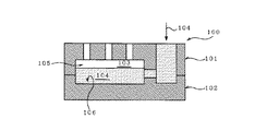
鋳造工法の一つである砂型鋳造法は、図10に示すように、上型(砂型)101と下型(砂型)102とを組み合わせてなる鋳型100を用いて鋳造を行う。この時、上型101と下型102の各窪み部105,106で囲まれた空間が、最終製品とほぼ同形状のキャビティ103を形成する。このキャビティ103内に金属溶湯104を注湯し、その金属溶湯104を凝固させた後、上型101と下型102の砂落としを行うことで、鋳造体、結果として鋳造製品(図示せず)が得られる。
As shown in FIG. 10, a sand mold casting method, which is one of the casting methods, performs casting using a
鋳造体の強度を向上させる1つの方法として、金属溶湯の冷却速度を高めて鋳造体の鋳造組織を微細化するというものがある。この方法は、冷却速度が速い金型鋳造法に好適である。ところが、金型鋳造法は、鋳型の製造費が高価であり、かつ、一旦鋳型(金型)を作製すると、型変更が困難であることから、大量生産品には適しているものの、試作品や少量生産品にはコスト的に見合わない。 One method for improving the strength of the cast body is to increase the cooling rate of the molten metal to refine the cast structure of the cast body. This method is suitable for a die casting method having a high cooling rate. However, the mold casting method is suitable for mass-produced products because the mold manufacturing cost is expensive and it is difficult to change the mold once the mold (mold) is manufactured. And it is not worth the cost for low-volume products.
これに対して、砂型鋳造法は、鋳型の製造費が安価であり、かつ、型の変更も容易であることから、試作品や少量生産品に適した鋳造方法である。ところが、砂型鋳造法における金属溶湯の冷却速度は、鋳物砂の熱伝導率に依存しており、冷却速度が極めて遅い。このため、砂型鋳造法においては、冷却速度の向上が各種試みられてきた。 On the other hand, the sand mold casting method is a casting method suitable for prototypes and low-volume products because the mold manufacturing cost is low and the mold can be easily changed. However, the cooling rate of the molten metal in the sand casting method depends on the thermal conductivity of the foundry sand, and the cooling rate is extremely slow. For this reason, various attempts have been made to improve the cooling rate in the sand casting method.
例えば、鋳型の冷却を促進したい部位に、冷し金を埋込んだり、強磁性体で構成される粒状吸熱体を磁着させたりした鋳造用砂型がある(特許文献1参照)。また、熱伝導率の良好な鋳物砂を用いて構成した鋳造用砂型がある(例えば、特許文献2〜5参照)。 For example, there is a sand mold for casting in which cooling metal is embedded in a portion where cooling of the mold is desired to be promoted or a granular endothermic body made of a ferromagnetic material is magnetized (see Patent Document 1). Moreover, there exists a sand mold for casting comprised using casting sand with favorable thermal conductivity (for example, refer patent documents 2-5).
ところで、前述した冷し金を埋込んだり、粒状吸熱体を磁着させるという手法を、鋳型の広い範囲にわたって適用する場合、金型鋳造法と同様に鋳型の製造費が高価になるという問題があった。 By the way, when the above-described method of embedding the cooling metal or magnetizing the granular endothermic material is applied over a wide range of the mold, there is a problem that the manufacturing cost of the mold becomes high like the mold casting method. there were.
また、熱伝導率の良好な鋳物砂で鋳造用砂型を構成する場合においても、鋳造用砂型全体を鋳物砂で構成していることから、鋳型の製造費が高価になるという問題があった。更に、この場合、鋳型の重量増を招いてしまい、結果的に、鋳造時における人力での鋳型のハンドリングが悪くなってしまうという問題があった。 Further, even when the casting sand mold is made of casting sand having a good thermal conductivity, there is a problem that the manufacturing cost of the mold becomes expensive because the entire casting sand mold is made of casting sand. Further, in this case, there is a problem that the weight of the mold is increased, and as a result, the handling of the mold by manpower at the time of casting is deteriorated.
以上の事情を考慮して創案された本発明の目的は、冷却速度が速く、安価で、軽量な鋳造用砂型を提供することにある。 An object of the present invention, which was created in view of the above circumstances, is to provide a casting sand mold that has a high cooling rate, is inexpensive, and is lightweight.
上記目的を達成すべく本発明に係る鋳造用砂型は、砂型鋳造法に用いる鋳型であり、砂型のキャビティを取り囲むように、かつ、鋳型面に臨んで、銅粒で構成される銅鋳型部を設けたものである。 The casting sand mold according to the present invention to achieve the above object is a mold used in the sand casting method, and a copper mold portion composed of copper grains is formed so as to surround the cavity of the sand mold and face the mold surface. It is provided.
ここで、銅鋳型部を構成する銅粒の平均粒径が0.2〜0.5mmであることが好ましい。銅鋳型部の、キャビティ取り囲み厚さが30〜50mmであることが好ましい。砂型は、少なくとも2つの砂型部材を組み合わせてなるものであってもよい。 Here, it is preferable that the average particle diameter of the copper grain which comprises a copper casting_mold | template part is 0.2-0.5 mm. It is preferable that the cavity surrounding thickness of the copper mold part is 30 to 50 mm. The sand mold may be a combination of at least two sand mold members.
一方、本発明に係る鋳造用砂型の製造方法は、
型枠内に最終製品とほぼ同形状の木型を配置するステップA、
型枠内に銅粒を装填して木型を覆うように銅粒層を形成するステップB、
型枠内に鋳物砂を充填して砂型本体部を構成する鋳物砂層を形成するステップC、
及び木型を取り除くステップD、
を有するものである。
On the other hand, the method for producing a casting sand mold according to the present invention is as follows.
Step A in which a wooden pattern having the same shape as the final product is placed in the mold,
Step B of forming a copper grain layer so as to cover the wooden mold by loading copper grains in the mold,
Step C for forming a casting sand layer constituting the sand mold main body by filling the mold with casting sand,
And step D to remove the mold.
It is what has.
ここで、ステップBが、
型枠内に、木型を取り囲む内枠を配置するステップB1、
その内枠内に銅粒を装填して木型を覆うように銅粒層を形成するステップB2、
を備えていてもよい。
Here, step B is
Step B1 of arranging an inner frame surrounding the wooden pattern in the mold frame,
Step B2 of forming a copper grain layer so as to cover the wooden mold by loading copper grains in the inner frame;
May be provided.
ステップBは、更に、
ステップB2の後に銅粒層を粘結剤を用いて固化させるステップB3、
を備えている。
Step B further includes
Step B3 for solidifying the copper particle layer with a binder after Step B2,
It has.
また、ステップBは、更に、
ステップB3の後に内枠を取り除くステップB4、
を備えている。
Step B further includes
Step B4 for removing the inner frame after Step B3,
It has.
また、木型が少なくとも2つの木型部材で構成され、各木型部材を用いて砂型部材を形成し、各砂型部材を組み合わせて砂型を形成するようにしてもよい。 Alternatively, the wooden mold may be composed of at least two wooden mold members, each wooden mold member may be used to form a sand mold member, and each sand mold member may be combined to form a sand mold.
他方、本発明に係る鋳造製品は、上述した鋳造用砂型のキャビティ内に金属溶湯を注湯し、その金属溶湯を凝固させてなるものである。 On the other hand, the cast product according to the present invention is obtained by pouring a molten metal into the above-described cavity of the casting sand mold and solidifying the molten metal.
本発明によれば、金型と同程度の冷却速度を有する鋳造用砂型を得ることができるという優れた効果を発揮する。 According to this invention, the outstanding effect that the sand mold for casting which has a cooling rate comparable as a metal mold | die can be obtained is exhibited.
以下、本発明の好適一実施の形態を添付図面に基づいて説明する。 DESCRIPTION OF EXEMPLARY EMBODIMENTS Hereinafter, a preferred embodiment of the invention will be described with reference to the accompanying drawings.
本発明の好適一実施の形態に係る鋳造用砂型の横断面図を図1に示す。 FIG. 1 shows a cross-sectional view of a casting sand mold according to a preferred embodiment of the present invention.
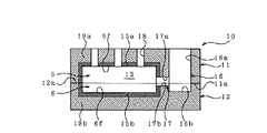
図1に示すように、本実施の形態に係る鋳造用砂型10は、上型(砂型)11の合わせ面11a及び下型(砂型)12の各合わせ面11a,12aを重ね合わせ、組み合わせたものである。
As shown in FIG. 1, a
上型11及び下型12の各合わせ面11a,12aには、それぞれ凹状の窪み部5,6が形成され、各窪み部5,6の表面が鋳型面5f,6fとなる。上型11及び下型12の各窪み部5,6が、それぞれ上型キャビティ及び下型キャビティを形成する。上型キャビティ(窪み部)5と下型キャビティ(窪み部)6とで囲まれた空間が、最終製品とほぼ同形状のキャビティ13を形成する。
Recessed
上型キャビティ5(又は下型キャビティ6)を取り囲むように、かつ、上型11の鋳型面5f(又は下型12の鋳型面6f)に臨んで、銅粒で構成される層状の銅鋳型部15a(又は15b)が設けられる。上型11(又は下型12)における銅鋳型部15a(又は15b)を除いた残部が、砂型本体部19a(又は19b)となる。
A layered copper mold part composed of copper grains so as to surround the upper mold cavity 5 (or the lower mold cavity 6) and face the
上型11には、上型11の垂直方向(図1中では上下方向)に貫通する貫通穴16aと溝17aとが設けられる。また、下型12には、穴16b及び溝17bが設けられる。上型11と下型12とを組み合わせることで、貫通穴16aと穴16bが重なって湯口16が形成され、溝17aと溝17bが重なって湯道17が形成される。キャビティ13は、湯道17、湯口16を介して、鋳型10の外面と連通される。さらに、上型11には、鋳型面5fと上型11の外面とを連通させるガス抜き穴18が形成される。
The
湯口16及び湯道17の内、湯道17におけるキャビティ13側端部(図1中では左端部)のみが銅鋳型部15(銅鋳型部15a,15b)で取り囲まれ、その他の部分は砂型本体部19a,19bで取り囲まれる。
Of the
ここで、図1に示した鋳造用砂型10のキャビティ13と、図10に示した鋳造用砂型100のキャビティ103の容積を同じ(又はほぼ同じ)とした場合、鋳造用砂型10における湯口16及び湯道17は、鋳造用砂型100のそれと比較して、十分に大きな断面積、好ましくは約3倍の断面積となるように形成される。
Here, when the volume of the
銅鋳型部15を構成する銅粒の平均粒径は、熱伝導効率、ガス抜け性を考慮して、例えば0.2〜0.5mmとされる。銅鋳型部15によるキャビティ13の取り囲み厚さは、キャビティ13の大きさ(容積)に応じて適宜変更されるものであり、例えば30〜50mmとされる。
The average particle diameter of the copper grains constituting the copper mold part 15 is set to, for example, 0.2 to 0.5 mm in consideration of the heat conduction efficiency and the gas release property. The surrounding thickness of the
銅粒としては、冷却速度を重視する場合、純銅や熱伝導率の高いCu合金が好ましく、銅粒の耐久性を重視する場合、耐熱性の高いCu合金が好ましい。また、銅粒は、鋳造製品の機械的特性や外観などに悪影響を及ぼす元素を含んでいない(又はその含有量が極めて少ない)ことが重要である。 As the copper particles, pure copper or a Cu alloy having high thermal conductivity is preferable when importance is attached to the cooling rate, and Cu alloy having high heat resistance is preferable when importance is attached to durability of the copper particles. In addition, it is important that the copper grains do not contain (or have a very small content of) elements that adversely affect the mechanical properties and appearance of the cast product.
次に、本実施の形態に係る鋳造用砂型10の製造方法を、添付図面に基づいて説明する。
Next, the manufacturing method of the
先ず、図1に示した上型11を製造する。図4(a)、図4(b)に示すように、矩形状の型枠41を準備する。この型枠41は、定盤42上に載置される。
First, the
型枠41内に、最終製品とほぼ同形状の木型43を配置する(ステップA)。同様にして、図1に示した湯口16、湯道17、及びガス抜き穴18を形成するための、湯口中子46、湯道中子47、及びガス抜き中子48が、型枠41内に配置される。
A
次に、型枠41内に銅粒45を装填し、木型43を覆うように銅粒層を形成する(ステップB)。より具体的には、型枠41内に、木型43を取り囲むように内枠44を配置する(ステップB1)。その後、内枠44内に銅粒45を装填して木型43を覆うように銅粒層を形成する(ステップB2)。その後、粘結剤により、銅粒層を固化させる(ステップB3)。その後、銅粒層を固化させてなる銅固化体45a(図5(a)、図5(b)参照)から、内枠44を取り除く(ステップB4)。この銅固化体45aが、図1に示した銅鋳型部15aを構成する。
Next, the
次に、図5(a)、図5(b)に示すように、型枠41内に鋳物砂51を充填し、鋳物砂層を形成する(ステップC)。その後、粘結剤により、この鋳物砂層を固化させる。自硬性の粘結剤を用いた場合、そのままの状態で固化が生じる。また、CO2法などのガスタイプの粘結剤を用いた場合、CO2などのガスを吹き込むことで固化が生じる。鋳物砂層を固化させてなる砂固化体51aが、図1に示した砂型本体部19aを構成する。
Next, as shown in FIGS. 5A and 5B, the
次に、型枠41内の銅固化体45a及び砂固化体51aから、木型43を取り除く(ステップD)。この木型43を取り除いた部分が、上型キャビティ5となる。同様にして、型枠41内の銅固化体45a及び砂固化体51aから、湯口中子46、湯道中子47、及びガス抜き中子48を取り除く。これらを取り除いた部分が、それぞれ湯口16、道17、及びガス抜き穴18となる。
Next, the
以上の手順により、図1に示した上型11が得られる。また、木型、湯口中子、湯道中子の形状が異なり、かつ、ガス抜き中子を用いない以外は、上型11の作製手順と同様にして、図1に示した下型12が得られる。
By the above procedure, the
このようにして得られた上型11と下型12の各合わせ面11a,12aを重ね合わせ、組み合わせることで、鋳造用砂型10が得られる。
The casting
次に、本実施の形態に係る鋳造用砂型10を用いた鋳造方法及びその作用を、添付図面に基づいて説明する。
Next, a casting method using the casting
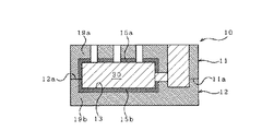
図2に示すように、鋳造用砂型10の湯口16から金属溶湯14が注湯される。金属溶湯14は、湯道17を介してキャビティ13内に充填される。この時、金属溶湯14の注湯に伴って発生したガスGは、ガス抜き穴18から排出される。
As shown in FIG. 2,
金属溶湯14が湯口16及び湯道17を通過し、キャビティ13に達すると、熱伝導率の高い銅鋳型部15a,15bに接触される。これによって、金属溶湯14が急冷される。冷却速度は、例えば、1.0℃/sec以上、好ましくは2.0℃/sec以上とされる。
When the
この急冷によって、金属溶湯14の湯流れ性の悪化が予測される。そこで、湯口16についてはその全長を、湯道17についてはその大部分を、砂固化体51a内部に形成している(砂型本体部19a,19bで取り囲んでいる)。また、湯口16及び湯道17の断面積は、図10に示した従来の鋳造用砂型100における湯口及び湯道のそれよりも十分に大きく形成している。よって、金属溶湯14が湯口16及び湯道17を通過する際に、注湯時の温度をほぼ保つことができ、また、十分な流速、流量を確保することができる。
Due to this rapid cooling, deterioration of the hot metal flow property of the
このように金属溶湯14がキャビティ13内で急速に冷却され、凝固することで、図3に示すように、微細な鋳造組織の鋳造体30が得られる。その後、上型11と下型12の砂落としを行うことで、鋳造体30が分離、回収される。回収された鋳造体30に後処理(砂落し、酸洗い、熱処理など)を施すことで、鋳造製品(図示せず)が得られる。砂落としによって、銅鋳型部15a,15bはブロック状に破砕され、銅粒として回収される。回収された銅粒は、再生処理を施すことで図4(a)、図4(b)に示した銅粒45となり、繰り返し利用される。
In this way, the
本実施の形態に係る鋳造用砂型10は、鋳造時における冷却速度を速めることで、鋳造組織の微細化を図り、強度向上を達成可能な鋳造用金属(又は合金)に全て適用可能である。例えば、鋳造用砂型10は、Al又はAl合金、Mg又はMg合金、鋳鉄合金などの鋳型として適用され、特に、急冷凝固により特性が大幅に向上されるMg又はMg合金に好適である。
The casting
金属溶湯14として、Al合金(AC4C合金)を用いた場合、鋳造体30における鋳造組織の微細化程度を、DAS(Dendrite Arm Spacing)値を用いて表現すると、例えば、鋳造体30のDAS値は40μm未満、好ましくは30μm未満とされる。また、この場合、鋳造組織の微細化程度を、引張強度を用いて表現すると、例えば、鋳造体30の引張強度は300MPa以上、好ましくは320MPa以上とされる。
When an Al alloy (AC4C alloy) is used as the
以上に示したように、本実施の形態に係る鋳造用砂型10では、銅粒45は、鋳造用砂型10の一部である銅鋳型部15a,15bに使用されているだけであり、鋳造用砂型10全体に占める使用割合は少ない。よって、熱伝導率の良好な鋳物砂を用いて鋳型全体を構成した従来の鋳造用砂型と比較して、本実施の形態に係る鋳造用砂型10は、銅粒45の使用割合が大幅に少なくて済む。
As described above, in the casting
ここで、鋳造体30が試作品や少量生産品である場合、コスト的にオートメーション化が困難であることから、必然的に人力による作業が多くなる。鋳型全体を銅粒45で構成すると、鋳型の大幅な重量増を招いてしまい、結果的に人力によるハンドリングが困難となってしまう。しかし、本実施の形態に係る鋳造用砂型10では、銅粒45で構成した銅鋳型部15a,15bは、キャビティ13の周辺部のみに限定的に配置されているだけであり、鋳型の重量増を最小限に抑えることができる。
Here, when the
また、本実施の形態に係る鋳造用砂型10は、砂型でありながら金型と同程度の冷却速度を有しており、かつ、銅粒45の使用割合が少ないことから安価に製造することができる。
Further, the casting
さらに、本実施の形態に係る鋳造用砂型10は、冷却速度を金型と同程度に高めながら、製品形状の変更に対する対応性が良好であるといった砂型の利点はそのまま活かすことができる。
Furthermore, the casting
また、本実施の形態に係る鋳造用砂型10は、銅粒45の使用割合が少ないことから、銅粒45の再生量も少なくて済み、再生コストの低減を図ることができる。結果的に、鋳造体30の製造コストの低減を図ることができる。
Further, since the casting
本実施の形態に係る鋳造用砂型10を用いて製造した鋳造製品(鋳造体30)は、軽量、薄肉、高強度な鋳造製品、例えば自動車部品に適用可能であり、特に、内燃機関用のシリンダブロック(又はピストン)、シリンダヘッド、タービン、油圧シリンダボディ等に好適である。
The cast product (cast body 30) manufactured using the casting
次に、本発明の他の実施の形態を添付図面に基づいて説明する。 Next, another embodiment of the present invention will be described with reference to the accompanying drawings.
前実施の形態に係る鋳造用砂型10においては、鋳型が2つの砂型部材(図1中では上型11と下型12)で構成される場合について説明を行ったが、特にこれに限定するものではない。例えば、目的とする鋳造製品の形状が複雑な場合、上型と下型の2分割構造では対応できない場合がある。よって、この場合、鋳造用砂型のキャビティを形成するための木型を3分割以上の寄せ型(割り型)とし、各分割型ごとに砂型部材を作製する。そして、少なくとも3つの砂型部材を組み合わせることで、鋳型が得られる。
In the casting
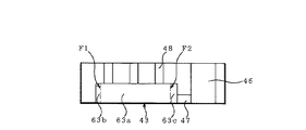
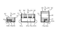
具体的には、図4(a)に示した上型11を形成するための木型43、湯口中子46、湯道中子47、及びガス抜き中子48の内、木型43が、図6に示すように、分割面F1,F2により分割可能な3分割構造とされる。つまり、木型43が分割体(木型部材)63a,63b,63cで構成される。
Specifically, among the
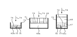
この場合、図7に示すように、分割体63aとガス抜き中子48は、図6に示した状態のまま、型枠71内に配置される。その後、型枠71内に銅粒74を装填し、分割体63aを覆うように銅粒層が形成される。
In this case, as shown in FIG. 7, the
また、図7に示すように、分割体63bは、分割面F1を下にした状態で型枠72内に配置される。その後、型枠72内に銅粒74を装填し、分割体63bを覆うように銅粒層が形成される。この時、型枠72内に仕切り板75を配置し、型枠72の内面における斜線領域76に銅粒74が装填されないようにする。または、仕切り板75を配置せず、型枠72の内面全体に銅粒74を装填するようにしてもよい。
Moreover, as shown in FIG. 7, the
さらに、図7に示すように、分割体63c、湯口中子46、及び湯道中子47は、分割体63cの分割面F2を下にした状態で型枠73内に配置される。その後、型枠73内に銅粒74を装填し、分割体63cを覆うように銅粒層が形成される。この時、型枠73内に仕切り板77を配置し、型枠73の内面における斜線領域78に銅粒74が装填されないようにする。または、仕切り板77を配置せず、型枠73の内面全体に銅粒74を装填するようにしてもよい。
Further, as shown in FIG. 7, the divided
その後、各型枠71,72,73内の銅粒層を、粘結剤により固化させ、銅固化体74a(図8参照)を形成する。
Thereafter, the copper particle layer in each of the
次に、図8に示すように、型枠71内に鋳物砂84を充填し、銅粒層の上に鋳物砂層が形成される。これによって、上型本体部(砂型部材)81が形成される。また、図8に示すように、型枠72内に鋳物砂84を充填し、銅粒層の上に鋳物砂層が形成される。これによって、第1寄せ型(砂型部材)82が形成される。さらに、図8に示すように、型枠73内に鋳物砂84を充填し、銅粒層の上に鋳物砂層が形成される。これによって、第2寄せ型(砂型部材)83が形成される。
Next, as shown in FIG. 8, the
その後、各型枠71,72,73内の鋳物砂層を、粘結剤により固化させ、砂固化体84a(図9参照)を形成する。
Thereafter, the foundry sand layer in each of the
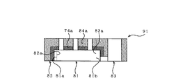
次に、図9に示すように、上型本体部81の合わせ面81aと第1寄せ型82の合わせ面82a、及び上型本体部81の合わせ面81bと第2寄せ型83の合わせ面83aを重ね合わせ、組み合わせる。これにより、3分割構造の上型91が得られる。上型91における銅固化体74a、砂固化体84aが、それぞれ図1に示した上型11における銅鋳型部15a、砂型本体部19aに相当する。
Next, as shown in FIG. 9, the
以上のようにして得られた上型91を、図1に示した下型12、又は上型91の作製手順と同様にして作製した下型(図示せず)と重ね合わせ、組み合わせることで、少なくとも4つの砂型部材で構成される鋳造用砂型が得られる。
By superposing and combining the
以上、本発明は、上述した実施の形態に限定されるものではなく、他にも種々のものが想定されることは言うまでもない。 As described above, the present invention is not limited to the above-described embodiment, and it goes without saying that various other things are assumed.
次に、本発明について、実施例に基づいて説明するが、本発明はこの実施例に限定されるものではない。 Next, although this invention is demonstrated based on an Example, this invention is not limited to this Example.
本発明の鋳造用砂型(図1に示した鋳造用砂型10を参照)と従来の鋳造用砂型(図10に示した鋳造用砂型100を参照)を用い、それぞれAl合金(AC4C合金)製の鋳造製品を作製した。
The casting sand mold of the present invention (see the casting
各鋳造製品の鋳造工程において、Al合金溶湯の凝固時の冷却速度を、熱電対を用いて実測した。その結果、従来の鋳造用砂型の冷却速度が0.4℃/secであったのに対し、本発明の鋳造用砂型の冷却速度は2.6℃/secであった。このことから、本発明の鋳造用砂型を用いて鋳造を行うことで、鋳造時の冷却速度を大幅に向上できることが確認された。 In the casting process of each cast product, the cooling rate during solidification of the Al alloy molten metal was measured using a thermocouple. As a result, the cooling rate of the conventional casting sand mold was 0.4 ° C./sec, whereas the cooling rate of the casting sand mold of the present invention was 2.6 ° C./sec. From this, it was confirmed that the cooling rate at the time of casting can be significantly improved by casting using the casting sand mold of the present invention.
また、各鋳造製品について、DAS値による鋳造組織の大きさを測定した。その結果、従来の鋳造用砂型を用いて作製した鋳造製品のDAS値が約50μmであったのに対し、本発明の鋳造用砂型を用いて作製した鋳造製品のDAS値は約25μmであった。このことから、本発明の鋳造用砂型を用いて鋳造を行うことで、鋳造製品の鋳造組織が微細化されることが確認された。 For each cast product, the size of the cast structure was measured according to the DAS value. As a result, the DAS value of the casting product produced using the conventional casting sand mold was about 50 μm, whereas the DAS value of the casting product produced using the casting sand mold of the present invention was about 25 μm. . From this, it was confirmed that the cast structure of the cast product is refined by casting using the casting sand mold of the present invention.
さらに、各鋳造製品について、引張強度を測定した。その結果、従来の鋳造用砂型を用いて作製した鋳造製品の引張強度が295MPaであったのに対し、本発明の鋳造用砂型を用いて作製した鋳造製品の引張強度は328MPaであった。このことから、本発明の鋳造用砂型を用いて鋳造を行うことで、鋳造製品の引張強度が約10%以上も向上することが確認された。 Further, the tensile strength was measured for each cast product. As a result, the tensile strength of the casting product produced using the conventional casting sand mold was 295 MPa, whereas the tensile strength of the casting product produced using the casting sand mold of the present invention was 328 MPa. From this, it was confirmed that the tensile strength of the cast product is improved by about 10% or more by performing casting using the sand mold for casting of the present invention.
5f,6f 鋳型面
10 鋳造用砂型
13 キャビティ
15a,15b 銅鋳型部
45 銅粒
5f, 6f
Claims (10)
型枠内に最終製品とほぼ同形状の木型を配置するステップA、
型枠内に銅粒を装填して木型を覆うように銅粒層を形成するステップB、
型枠内に鋳物砂を充填して砂型本体部を構成する鋳物砂層を形成するステップC、
及び木型を取り除くステップD、
を有することを特徴とする鋳造用砂型の製造方法。 In the method for producing a sand mold for casting used in the sand mold casting method,
Step A in which a wooden pattern having the same shape as the final product is placed in the mold,
Step B of forming a copper grain layer so as to cover the wooden mold by loading copper grains in the mold,
Step C for forming a casting sand layer constituting the sand mold main body by filling the mold with casting sand,
And step D to remove the mold.
A method for producing a sand mold for casting, comprising:
上記型枠内に、木型を取り囲む内枠を配置するステップB1、
その内枠内に銅粒を装填して木型を覆うように銅粒層を形成するステップB2、
を備えた請求項5記載の鋳造用砂型の製造方法。 Step B above
Step B1 of arranging an inner frame surrounding the wooden mold in the mold frame,
Step B2 of forming a copper grain layer so as to cover the wooden mold by loading copper grains in the inner frame;
A method for producing a sand mold for casting according to claim 5, comprising:
上記ステップB2の後に上記銅粒層を粘結剤を用いて固化させるステップB3、
を備えた請求項5又は6記載の鋳造用砂型の製造方法。 Step B above further includes
Step B3 for solidifying the copper grain layer with a binder after Step B2;
A method for producing a sand mold for casting according to claim 5 or 6.
上記ステップB3の後に上記内枠を取り除くステップB4、
を備えた請求項6又は7記載の鋳造用砂型の製造方法。 Step B above further includes
Step B4 for removing the inner frame after Step B3,
A method for producing a sand mold for casting according to claim 6 or 7, comprising:
5. A casting product, wherein molten metal is poured into a cavity of the sand mold for casting according to any one of claims 1 to 4, and the molten metal is solidified.
Priority Applications (1)
| Application Number | Priority Date | Filing Date | Title |
|---|---|---|---|
| JP2004114236A JP2005296980A (en) | 2004-04-08 | 2004-04-08 | Sand mold for casting |
Applications Claiming Priority (1)
| Application Number | Priority Date | Filing Date | Title |
|---|---|---|---|
| JP2004114236A JP2005296980A (en) | 2004-04-08 | 2004-04-08 | Sand mold for casting |
Publications (1)
| Publication Number | Publication Date |
|---|---|
| JP2005296980A true JP2005296980A (en) | 2005-10-27 |
Family
ID=35329161
Family Applications (1)
| Application Number | Title | Priority Date | Filing Date |
|---|---|---|---|
| JP2004114236A Pending JP2005296980A (en) | 2004-04-08 | 2004-04-08 | Sand mold for casting |
Country Status (1)
| Country | Link |
|---|---|
| JP (1) | JP2005296980A (en) |
Cited By (2)
| Publication number | Priority date | Publication date | Assignee | Title |
|---|---|---|---|---|
| JP2013141697A (en) * | 2012-01-12 | 2013-07-22 | Mitsubishi Heavy Ind Ltd | Sand mold casting device and sand mold casting method |
| CN114833312A (en) * | 2022-05-08 | 2022-08-02 | 广西嘉树州驰数据科技有限责任公司 | Aluminum bar casting system and method |
-
2004
- 2004-04-08 JP JP2004114236A patent/JP2005296980A/en active Pending
Cited By (3)
| Publication number | Priority date | Publication date | Assignee | Title |
|---|---|---|---|---|
| JP2013141697A (en) * | 2012-01-12 | 2013-07-22 | Mitsubishi Heavy Ind Ltd | Sand mold casting device and sand mold casting method |
| CN114833312A (en) * | 2022-05-08 | 2022-08-02 | 广西嘉树州驰数据科技有限责任公司 | Aluminum bar casting system and method |
| CN114833312B (en) * | 2022-05-08 | 2024-04-09 | 江西广硕金属制品有限公司 | Aluminum bar casting system and method |
Similar Documents
| Publication | Publication Date | Title |
|---|---|---|
| CN101406932B (en) | Precision-investment casting method | |
| CN100381230C (en) | Method for producing light-alloy casting | |
| CN104999051A (en) | Low-pressure casting method for automobile motor casing and motor casing structure | |
| CN101928872B (en) | Production method of low-magnetism iron casting | |
| CN107971464B (en) | Mould for producing double-screw extruder barrel bushing | |
| JP5339764B2 (en) | Casting method | |
| CN1066361C (en) | Method for casting scroll | |
| CN113547100A (en) | Method for manufacturing bimetal composite component | |
| KR20120042652A (en) | Sand casting a diesel piston with an as-cast, reentrant combustion bowl | |
| JP2004058098A (en) | Metallic mold for casting | |
| US10898948B2 (en) | Method of manufacturing metal castings | |
| JP2005296980A (en) | Sand mold for casting | |
| JP4170793B2 (en) | Compound mold manufacturing method | |
| US20050016710A1 (en) | Chill blocks and methods for manufacturing chill blocks | |
| JP5726985B2 (en) | Mold for casting | |
| JP6917964B2 (en) | Aluminum alloy casting and its manufacturing method | |
| JP2005271006A (en) | Mold for casting and manufacturing method thereof | |
| JPH0399767A (en) | Method for manufacturing internal chilling piping in casting metallic mold | |
| JP7456587B1 (en) | Mold and its manufacturing method | |
| JP2008260048A (en) | Casting method | |
| CN217701297U (en) | Die casting die for producing high-air-tightness disc brake oil pump | |
| JPS6072639A (en) | Production of piston | |
| JP2005021962A (en) | Mold manufacturing method, mold and casting | |
| US10960464B2 (en) | Method of casting heterogeneous materials and a casting product manufactured thereby | |
| JPH07178531A (en) | Casting method and casting device for disc material for forging in road wheel |