JP2005296961A - Solder dissolver - Google Patents
Solder dissolver Download PDFInfo
- Publication number
- JP2005296961A JP2005296961A JP2004112674A JP2004112674A JP2005296961A JP 2005296961 A JP2005296961 A JP 2005296961A JP 2004112674 A JP2004112674 A JP 2004112674A JP 2004112674 A JP2004112674 A JP 2004112674A JP 2005296961 A JP2005296961 A JP 2005296961A
- Authority
- JP
- Japan
- Prior art keywords
- solder
- temperature
- container
- melting
- melting container
- Prior art date
- Legal status (The legal status is an assumption and is not a legal conclusion. Google has not performed a legal analysis and makes no representation as to the accuracy of the status listed.)
- Pending
Links
Images


Landscapes
- General Induction Heating (AREA)
Abstract
【課題】 容器内の突沸現象を防ぎつつ、短時間で半田を溶解させることができ、しかも容器の交換を容易に行う。
【解決手段】 溶解容器11を本体1から着脱自在とすることで、溶解容器11を容易に交換することが可能となる。また、加熱手段としての誘導加熱コイル27は、誘導加熱により半田10を溶解させる加熱部としての側周方向コイル27aと底面コイル27bを、溶解容器11の側面と底面に配置して構成される。これにより、溶解容器11内の半田10に対する温度ムラを防いで、溶解容器11の底面方向のみならず側面方向からも半田10を均一に溶解させて、突沸現象を確実に防ぐことができる。
【選択図】 図1PROBLEM TO BE SOLVED: To dissolve solder in a short time while preventing a bumping phenomenon in a container and to easily replace the container.
By making the dissolution container 11 detachable from the main body 1, the dissolution container 11 can be easily replaced. The induction heating coil 27 as a heating means is configured by arranging a side circumferential coil 27a and a bottom coil 27b as heating portions for melting the solder 10 by induction heating on the side surface and the bottom surface of the melting container 11. Accordingly, temperature unevenness with respect to the solder 10 in the melting container 11 can be prevented, and the solder 10 can be uniformly melted not only from the bottom surface direction but also from the side surface direction, thereby reliably preventing the bumping phenomenon.
[Selection] Figure 1
Description
本発明は、プリント基板に実装した部品の半田付け等に使用される半田溶解器に関する。 The present invention relates to a solder dissolver used for soldering components mounted on a printed circuit board.
各種電子機器の主要部を構成する回路部品をプリント基板へ実装する工程において、該回路部品の半田付けには一般的にフロー半田付けが行われる。これは、加熱手段としてのヒータにより溶解容器(半田槽ともいう)内に投入又は貯蔵した半田を溶解させ、該溶解半田にプリント基板の半田付け面を接触させることにより、プリント基板に装着した回路部品を一括して半田付けするものである。半田溶解器は主に前記フロー半田付けに使用され、加熱手段により半田を溶解するためのものである。 In the process of mounting circuit components constituting the main part of various electronic devices on a printed circuit board, flow soldering is generally performed for soldering the circuit components. This is a circuit mounted on a printed circuit board by melting the solder put in or stored in a melting container (also referred to as a solder tank) by a heater as a heating means, and bringing the soldered surface of the printed circuit board into contact with the molten solder. Parts are soldered together. The solder dissolver is mainly used for the flow soldering and is for melting the solder by a heating means.
図4はこのような従来の半田溶解器における一部切欠き断面図を示したものであるが、同図において、11は内部で半田10を溶解するための有底円筒状の溶解容器であり、12は例えばシーズヒータからなる加熱手段としてのヒータである。溶解容器11内にある固形の半田10は、溶解容器11の底部に設けられたヒータ12により加熱・溶解され、液状の半田10となる。この溶解した半田10は、ヒータ12により加熱されるが、その際、溶解容器11を介在して間接的に加熱されることとなる。
FIG. 4 is a partially cutaway sectional view of such a conventional solder dissolver. In FIG. 4, 11 is a bottomed cylindrical melting container for melting the
32は運転スイッチを兼ねた回動可能な調節用スイッチである。この調節用スイッチ32に対応して、本体1の正面には図示しないが例えば0から6までの目盛りがあり、この0から6までの目盛りには予め設定温度と、設定温度に応じたヒータ出力が割り付けてある。6を最高温度(最大出力)として、以下数字が少なくなるに従って設定温度(ヒータ12出力)が低くなり、0でオフ状態すなわち出力停止状態となる。
そして、運転開始時において、溶解容器11内に予め半田が凝固した状態にある時は、溶解容器11の温度立ち上がりを急にするために、調節用スイッチ32を最大出力である6に設定する。これは、最初から所望の温度に設定すると出力が低く、溶解容器11内の半田が溶解するまでに多くの時間を要することとなるため、運転開始時における出力を最大出力にして該時間を短縮しようという意図である。そして、半田10の温度が上昇し、ある程度半田10が溶解したら所望の温度に設定し直す。このようにすることで、最初から所望の温度に設定する場合と比べて比較的短い時間で、所望の半田温度を得ることができる。
When the solder is solidified in advance in the
また、同様の周知技術として、例えば特許文献1に開示されるような半田付け装置が知られている。ここでは、溶解容器としてのタンクと、タンクの底部に設けられた加熱手段としてのヒータとにより半田溶解器の主要部を構成し、タンク内に貯蔵された半田をヒータで加熱,溶融するようにしている。
このような従来の半田溶解器では、まず安全面における問題があった。これは加熱手段としてのヒータ12が溶解容器11の下部に一体に組み込まれていることに起因する。半田10を溶解する場合には、ヒータ12の熱が溶解容器11のみならず、ヒータ12周辺にある半田溶解器の本体1(機器外郭面)にまで伝播し高温となる。したがって、作業者が周囲で半田付け等の作業を行う際に、高温の機器外郭面に接触する虞れがあった。その上、ヒータ12は溶解容器11の下側にのみ設けられていることから、該ヒータ12の加熱能力を大きくすると、溶解容器11の底面側の半田が先に溶解し、溶解した半田10の上部に固形した半田10が蓋をした状態となる。このような状態は、固形した半田10の隙間から溶解した半田10が吹き上がる好ましくない突沸現象を招く。
Such a conventional solder dissolver has a safety problem. This is due to the fact that the
次に、使用上における問題として、加熱手段としては電熱線などからなるヒータ12が使用されるが、ヒータ12の能力が一定で運転開始から半田10が使用可能な状態になるまで、すなわち半田10が溶解するまでに多くの時間を要していた。また上述したように、運転開始時には立ち上がり時間を短くすべく、設定温度を所望の温度より高めに設定する強運転を行ない、半田10が溶解してから始めて所望の温度に設定し直すという方法が採られる。したがって、二度三度と温度設定をする必要があり作業性が悪かった。加えて、ヒータ12の定格にも左右されるが、ヒータ12に対する細かい温度コントロールが困難なため、溶解容器11内における半田温度の正確性がないという問題もあった。
Next, as a problem in use, the
また、長期使用による溶解容器11の劣化、例えば穴あき等により溶解容器11に不具合が起きた場合、溶解容器11が本体1から着脱できない構成となっているため、その交換が困難であった。以上のように従来の半田溶解器は種々の問題を有していた。
In addition, when the
そこで本発明は上記問題点に鑑み、容器内の突沸現象を防ぎつつ、短時間で半田を溶解させることができ、しかも容器の交換を容易に行うことができる半田溶解器を提供することを目的とする。 Therefore, in view of the above problems, the present invention has an object to provide a solder dissolver that can dissolve solder in a short time while preventing bumping phenomenon in the container, and can easily replace the container. And
また本発明の第2の目的は、途中で温度設定を変えなくても、短時間で半田を溶解させることができ、しかも容器内の半田に対して細かい温度コントロールが可能になる半田溶解器を提供することにある。 A second object of the present invention is to provide a solder dissolver that can dissolve solder in a short time without changing the temperature setting in the middle, and that enables fine temperature control over the solder in the container. It is to provide.
本発明の請求項1では、容器を着脱自在の構成としている。したがって、長期使用による容器の劣化が起きた場合でも、容器を容易に交換することが可能となる。また、容器又は半田は加熱手段により誘導加熱されるものであるため、従来の電熱ヒータによるものよりも短時間で容器内の半田を溶解できる。しかも、加熱手段を構成する加熱部は容器の側面と底面などの外側から誘導加熱することができるため、容器内の半田に対する温度ムラを防いで、容器の底面方向のみならず側面方向からも半田を均一に溶解させて、突沸現象を確実に防ぐことができる。 In claim 1 of the present invention, the container is configured to be detachable. Therefore, even when the container deteriorates due to long-term use, the container can be easily replaced. Further, since the container or the solder is heated by induction by the heating means, the solder in the container can be dissolved in a shorter time than that by the conventional electric heater. In addition, since the heating part constituting the heating means can be induction-heated from the outside such as the side and bottom of the container, temperature unevenness with respect to the solder in the container is prevented, and the solder is not only from the bottom of the container but also from the side. Can be dissolved uniformly to prevent the bumping phenomenon.
本発明の請求項2では、容器又は半田が加熱手段により誘導加熱されるため、従来の電熱ヒータによるものよりも短時間で容器内の半田を溶解できる。また、設定された温度と容器内の温度との差に応じて、加熱手段の加熱出力が可変されるため、運転途中で二度三度と温度設定をし直さなくても、容器内の半田を短時間で溶解できると共に、使用中に半田の補充を行なった場合も、加熱出力が直ぐに追従して容器内の温度低下を極力防ぐことができる。すなわち、加熱手段の出力を自動的に変えることができ、運転開始から半田作業が可能になるまでの時間が大幅に短縮されるため、工場内などで始業前や休憩時間中に設定温度を変更しながら通電を行なう必要がなくなり、使いやすくなる上に省エネルギー(省エネ)を達成できる。さらに、反応性の良い誘導加熱を使用して半田を直接加熱するため、細かい温度コントロールが可能となり、容器内の半田温度を正確に制御することができる。 According to the second aspect of the present invention, since the container or the solder is induction-heated by the heating means, the solder in the container can be dissolved in a shorter time than that by the conventional electric heater. In addition, since the heating output of the heating means is varied according to the difference between the set temperature and the temperature in the container, the solder in the container can be used without having to set the temperature again and again during the operation. Can be dissolved in a short time, and even when the solder is replenished during use, the heating output immediately follows and the temperature drop in the container can be prevented as much as possible. In other words, the output of the heating means can be changed automatically, and the time from the start of operation to the time when soldering can be performed is greatly reduced, so the set temperature can be changed before the start of work or during breaks in the factory. However, it is not necessary to energize, making it easy to use and energy saving. Furthermore, since the solder is directly heated using induction heating with good reactivity, fine temperature control is possible, and the solder temperature in the container can be accurately controlled.
本発明は、以上説明したようなものであるから、以下に記載されるような効果を奏する。 Since the present invention is as described above, the following effects can be obtained.
請求項1における発明では容器内の突沸現象を防ぎつつ、短時間で半田を溶解させることができ、しかも容器の交換を容易に行うことができる。 According to the first aspect of the present invention, the solder can be dissolved in a short time while preventing the bumping phenomenon in the container, and the container can be easily replaced.
請求項2における発明では、途中で温度設定を変えなくても、短時間で半田を溶解させることができ、しかも容器内の半田に対して細かい温度コントロールが可能になる。さらに、工場などでは使いやすさを向上できると共に省エネルギーを達成できる。 According to the second aspect of the present invention, the solder can be dissolved in a short time without changing the temperature setting on the way, and fine temperature control is possible for the solder in the container. In addition, ease of use can be improved and energy saving can be achieved in factories and the like.
以下、添付図面を参照しながら、本発明における半田溶解器の好ましい実施例を、その使用方法と共に説明する。なお、以下の実施例において、従来例と同一箇所には同一符号を付し、共通する部分の説明は重複するため極力省略する。 Hereinafter, a preferred embodiment of a solder dissolver according to the present invention will be described together with its usage method with reference to the accompanying drawings. In the following embodiments, the same portions as those in the conventional example are denoted by the same reference numerals, and the description of the common parts will be omitted as much as possible.
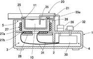
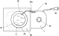
半田溶解器の外観をあらわす図1及び図2において、1は機器外郭部材としての本体であって、この本体1の内部は、間仕切り2により加熱室3と制御室4に左右方向に2分されており、加熱室3の高さは制御室4に比べて高く、段差状になっている。加熱室3の上方には開口部5が形成されており、該開口部5を覆う形で四角く形成された板状のトレイ20が取り付け固定されている。トレイ20は溶解半田が空気に触れることで生成される酸化皮膜すなわち半田屑を一次的に乗せるためのものであるため、耐熱性のある素材、例えば金属板を使用するのが好ましい。また、トレイ20に乗せた半田屑がこぼれ落ちないように、トレイ20の端部は一側を除いて上方向に壁面が形成されている。
In FIG. 1 and FIG. 2 showing the external appearance of the solder dissolver, 1 is a main body as a device outer member, and the inside of the main body 1 is divided into a
11は内部で半田10を溶解するための有底円筒状の容器たる溶解容器であり、この溶解容器11の上部開口部の周囲にはフランジ25が形成されている。溶解容器11内には、投入された半田10が半田溶解器の運転,停止の度に溶解,凝固を繰り返した状態で保持される。21はトレイ20の略中央に形成された開口穴であり、この開口穴21はフランジ25の外周径よりも小さく、開口穴21を通して加熱室3に溶解容器11を着脱自在に収容することができるようになっている。
A
前記加熱室3の上部には、溶解容器11が本体1の加熱室3に収容された状態において、溶解容器11の側面及び底面全体を覆い、溶解容器11を着脱自在に載置する断熱材26が取り付け固定される。該断熱材26は、溶解容器11の熱が本体1へ伝播するのを遮断している。断熱材26を溶解容器11自体に設置しても、同様の効果を得られることは言うまでもない。そして、溶解容器11の外側には、断熱材26を介して、加熱手段としての誘導加熱コイル27と、フェライトコア28が配置されている。誘導加熱コイル27は、溶解容器11の側面を取り巻くように配置された側周方向コイル27aと、溶解容器11の底面に対向して配置された底面コイル27bにより構成される。溶解容器11はそれ自体が磁性材料で形成されるか、さもなければ非磁性材料である容器母材の外面に磁性材料を接合して形成され、加熱部としての側周方向コイル27a及び底面コイル27bからの交番磁界により、該磁性材料にジュール熱が発生して溶解容器11を電磁誘導加熱し、この溶解容器11内に投入された半田10を溶解する構成となっている。
In the state where the melting
一方、本体1の制御室4には、誘導加熱コイル27を制御するための制御装置30が配置されており、電線31により誘導加熱コイル27と電気的に接続されている。制御装置30の上方には、調節用スイッチ32が本体1の上外面より突出する形で回動可能に設けられており、この調節用スイッチ32で設定された温度情報は、制御装置30にて判別され、溶解容器11内に投入された半田10の温度制御に使用される。溶解容器11内には、半田10の温度を測定するための例えばサーミスタなどの温度センサーからなる温度検出装置35が、溶解容器11内部側面に沿うように挿入されている。35aは、本体1上に配置された着脱自在の接続器36を介して、温度検出装置35と制御装置30とを電気的に接続するための信号線を内包する温度センサー接続部であり、トレイ20の端部に設けたスリット状の切り欠き20aに掛止されている。40は制御装置30に電源を供給するための電源コードであり、本実施例では、先端部分に商用電源コンセントに接続するためのプラグが装着されている。もちろん、制御装置30への電源供給は商用電源に限らず、各種電源を使用することが可能であることは言うまでもない。
On the other hand, a
次に、上記構成についてその作用を説明する。まず電源コード40を商用電源に接続し、調節用スイッチ32によって溶解容器11内に投入された半田10の温度を所望の設定温度にセットする。調節用スイッチ32は回転式、スライド式、ボタン式何れでも良いが、本実施例では回転式であり、従来例で示したような電源のオン/オフと半田10の温度設定を兼用するものとする。調節用スイッチ32の操作によって半田溶解器の電源がオンすると、制御装置30により誘導加熱コイル27の側周方向コイル27a及び底面コイル27bが通電され、溶解容器11の側周面及び底面の二面から誘導加熱によって溶解容器11及び半田10を加熱する。
Next, the operation of the above configuration will be described. First, the
使用初期においては、溶解容器11内は空の為、側周方向コイル27a及び底面コイル27bからの交番磁界によって溶解容器11自体が発熱する。ここで誘導加熱され高温となった溶解容器11に半田10を投入すると、溶解容器11に接する面から徐々に溶解し始め、溶解を始めた半田10は溶解容器11内底面に均一に行き渡る。このとき、半田10自体も誘導加熱によって加熱されることとなる。
In the initial stage of use, the melting
一方、溶解容器11内に冷えて凝固した半田10を再度使用する場合は、同様に電源コード40を商用電源に接続し、調節用スイッチ32を操作して所望の設定温度にセットする。これにより、側周方向コイル27aと底面コイル27bの各々から交番磁界が発生し、溶解容器11は側面と底面の両方から誘導加熱される。それに伴って、溶解容器11の内部にある半田10も、側面と底面の両方から溶融し始め、溶解容器11内の半田10による突沸現象を抑制することができる。
On the other hand, when the
上述したように、溶解容器11は誘導加熱コイル27により電磁誘導加熱されるが、これは同じ出力の電熱ヒータよりも熱効率がよく、溶解容器11及びその内部の半田10を速やかに温度上昇させることができる。
As described above, the melting
溶解した半田10の温度は温度検出装置35により検出され、該温度検出装置35からの検出温度情報は電気信号として温度センサー接続部35a及び接続器36を介して制御装置30に伝達される。制御装置30は温度検出装置35から伝達された検出温度と、調節スイッチ32で設定された前記設定温度の差を検出し、前記検出温度を設定温度に合致させるべく、誘導加熱コイル27に送る出力を変化させる。
The temperature of the melted
ここで、本実施例における制御装置30の制御動作を、図3を参照しながら以下に示す。同図は時間変化に対する前記温度検出装置35からの検出温度T2の変化を示したものである。また、T0は前記設定温度、T1はT0より所定の温度分低い温度を持つ制御変更点温度であり、T0の変更に応じてT1も変更(T0−T1は一定)される。
Here, the control operation of the
制御装置30では、以下に与えられる制御条件に従って、誘導加熱コイル27に送る出力を変化させる。T2≦T1の場合は大出力となり、T0>T2>T1かつT0−T2>(T0−T1)/2の場合は中出力となり、T0>T2>T1かつT0−T2<(T0−T1)/2の場合は小出力となり、T0<T2の場合は出力OFFである。これらの条件は、大出力の時はT0−T2≧T0−T1、中出力の時はT0−T1>T0−T2>(T0−T1)/2、小出力の時は0≦T0−T2<(T0−T1)/2、出力OFFの時はT0−T2<0とも表すことができ、いずれも設定温度T0と検出温度T2の差T0−T2と、一乃至複数の判定値との関係から、誘導加熱コイル27の加熱出力を変化させるものであるということがわかる。
In the
以下、具体的な数値を用い、上記温度制御について説明する。ここでは、溶解容器11内に予め凝固した半田10が貯蔵されている場合についての説明とする。また、設定温度T0を300℃、制御変更点温度T1を260℃とし、検出温度T2の運転開始時の温度を常温20℃とする。まず、運転開始時においては検出温度T2は20℃のため、T2≦T1となり、誘導加熱コイル27の出力は大出力となる。すると、溶解容器11及び半田10は誘導加熱により強発熱し、図3に示すように検出温度T2は時間経過とともに上昇してゆく。半田10の温度すなわち検出温度T2が半田10の融点(一般的な半田は約180℃)付近になると半田10は溶解容器11に接する側周面及び底面から徐々に溶解し始め、やがて半田10全部が溶解し、液状の溶解半田となる。
Hereinafter, the temperature control will be described using specific numerical values. Here, the case where the
その後、検出温度T2が制御変更点温度T1=260℃を超えると、設定温度T0と検出温度T2の差は、T0−T2<40℃となる。また、判定値は(T0−T1)/2=(300℃−260℃)/2=20℃であるため、このときT0>T2>T1かつT0-T2>(T0-T1)/2の条件を満たすこととなり、誘導加熱コイル27の出力はそれまでより小さくなって中出力となる。
Thereafter, when the detected temperature T2 exceeds the control change point temperature T1 = 260 ° C., the difference between the set temperature T0 and the detected temperature T2 becomes T0−T2 <40 ° C. Since the judgment value is (T0−T1) / 2 = (300 ° C.−260 ° C.) / 2 = 20 ° C., the conditions of T0> T2> T1 and T0-T2> (T0−T1) / 2 are satisfied. Thus, the output of the
同様に、時間経過と共に加熱が進み検出温度T2がT2=280℃を超えると、設定温度T0と検出温度T2の差は、T0−T2<20℃となる。このとき、判定値は20℃であるため、T0>T2>T1かつT0-T2<(T0-T1)/2の条件を満たすこととなり、誘導加熱コイル27の出力はさらに小さくなって小出力となる。
Similarly, when the heating proceeds with time and the detected temperature T2 exceeds T2 = 280 ° C., the difference between the set temperature T0 and the detected temperature T2 becomes T0−T2 <20 ° C. At this time, since the determination value is 20 ° C., the conditions of T0> T2> T1 and T0-T2 <(T0-T1) / 2 are satisfied, and the output of the
そして、さらに時間経過と共に加熱が進み検出温度T2が設定温度T0を超えると(T2>T0)、半田10がそれ以上の温度に上昇しないように、誘導加熱コイル27の加熱出力をオフにし、溶解容器11内の半田10を設定温度に維持するように制御する。
When the heating proceeds further with time and the detected temperature T2 exceeds the set temperature T0 (T2> T0), the heating output of the
ここでは3段階の変化例で説明したが更に多段に制御出力を変化させることにより木目細やかに温度制御できるのは言うまでもなく、制御方法として上記方法を使用せずに、周知の技術である例えばPID制御などを使用してもよい。 Although the three-stage change example has been described here, it is needless to say that the temperature can be finely controlled by changing the control output in more stages, and it is a well-known technique such as PID without using the above method as a control method. Control or the like may be used.
使用途中においては、上述したように、溶解した半田10は時間とともに酸化劣化する。溶解容器11の表面に酸化劣化膜が現れると、うまく半田付けが出来なくなる。除去棒(図示せず)などで該酸化劣化膜をトレイ20上に除去すると、新たに酸化していない半田面が現れるため半田付け作業が可能となる。
During use, as described above, the melted
以上のように本実施例では、加熱手段により容器である溶解容器11内の半田10を溶解させる半田溶解器において、溶解容器11を本体1から着脱自在とすると共に、加熱手段としての誘導加熱コイル27は、誘導加熱により半田10を溶解させる加熱部としての側周方向コイル27aと底面コイル27bを、溶解容器11の側面と底面に配置して構成される。
As described above, in this embodiment, in the solder dissolver that melts the
この場合、溶解容器11が着脱自在の構成となっているため、長期使用による溶解容器11の劣化が起きた場合でも、溶解容器11を容易に交換することが可能となる。また、溶解容器11と半田11は誘導加熱コイル27により誘導加熱されるものであるため、従来の電熱ヒータによるものよりも短時間で溶解容器11内の半田10を溶解できる。しかも、側周方向コイル27aと底面コイル27bは溶解容器11の側面と底面の二面に対向して誘導加熱することができるため、溶解容器11内の半田10に対する温度ムラを防いで、溶解容器11の底面方向のみならず側面方向からも半田10を均一に溶解させて、突沸現象を確実に防ぐことができる。
In this case, since the
しかも本実施例では、前記溶解容器11の側面及び底面に配置された断熱材26と、前記溶解容器11および半田10を加熱するための加熱手段を備え、誘導加熱により半田11を溶解させる誘導加熱コイル27で前記加熱手段を構成すると共に、溶解容器11の側面及び底面の二面に側周方向コイル27a及び底面コイル27bを配置し、断熱材26を介して溶解容器11及び半田10を加熱するように構成している。
In addition, in this embodiment, the
このようにすると、溶解容器11の外面を覆うように断熱材26を設けたことにより、溶解容器11の熱が本体1へ伝播するのを熱的に遮断している。そのため、高温部分が溶解容器11周辺に限定され安全性が著しく向上する。しかも、溶解容器11の周囲を断熱材26で覆っていることから、加熱部分が溶解容器11及び溶解容器11内部の半田10に限定される為、従来のヒータ一体式の半田溶解器に比べ、加熱ロスが少なく高効率となり省エネである。実験では、約25%〜30%程度省エネであり、従来使用開始状態になるまで30分かかっていたものが5,6分にまで大幅に短縮された。したがって、始業前や休憩時間中に通電する必要が無く省エネである。
In this case, the
さらに本実施例では、加熱手段により溶解容器11内の半田10を溶解させる半田溶解器において、誘導加熱により半田11を溶解させる例えば誘導加熱コイル27で加熱手段を構成し、設定温度と溶解容器11内の温度との差に応じて誘導加熱コイル27の出力を変化させる構成としている。
Furthermore, in this embodiment, in the solder dissolver that melts the
この場合、溶解容器11又は半田10が加熱手段により誘導加熱されるため、従来の電熱ヒータによるものよりも短時間で溶解容器11内の半田を溶解できる。また、設定温度T0と溶解容器11内の温度T2との差に応じて、誘導加熱コイル27の加熱出力が可変されるため、運転途中で二度三度と温度設定をし直さなくても、溶解容器11内の半田10を短時間で溶解できると共に、使用中に半田11の補充を行なった場合も、加熱出力が直ぐに追従して溶解容器11内の温度低下を極力防ぐことができる。すなわち、誘導加熱コイル27の出力を自動的に変えることができ、運転開始から半田作業が可能になるまでの時間が大幅に短縮されるため、工場内などで始業前や休憩時間中に設定温度を変更しながら通電を行なう必要がなくなり、使いやすくなる上に省エネルギーを達成できる。さらに、反応性の良い誘導加熱を使用して半田10を直接加熱するため、細かい温度コントロールが可能となり、溶解容器11内の半田温度を正確に制御することができる。
In this case, since the melting
また本実施例では、所望の半田温度を設定するための温度設定手段としての調節用スイッチ32と、前記溶解容器11内の半田10の温度を検出する温度検出手段としての温度検出装置35とを備え、調節用スイッチ32により設定された設定温度T0と温度検出装置35により検出された半田温度T2の差に応じて、前記加熱手段としての誘導加熱コイル27の出力が可変する。
In the present embodiment, an
このようにすると、従来手動で行っていた設定温度の変更を前記設定温度T0と前記検出温度T2の差に応じて自動的に行うため、運転途中で二度三度と温度設定をし直すことなく、立ち上がり時間を短縮することができる。したがって、運転操作が一動作で簡単であり、使用中における半田の補充等での温度低下時においても、自動的に出力が調整されるため溶解半田10の温度変動が少ない。また、温度検出手段としての温度検出装置35により半田10の温度を直接検出し、反応性の良い誘導加熱を使用して半田10を直接加熱するため、細かい温度コントロールが可能となり、半田温度のオーバーシュートを抑制し半田10の温度を正確に制御することができる。したがって、半田温度の設定における作業性を改善すると共に、正確な温度制御を容易にすることが可能となり、温度制御精度が著しく向上する。
In this way, since the change of the set temperature, which has been performed manually in the past, is automatically performed according to the difference between the set temperature T0 and the detected temperature T2, the temperature is set again and again during the operation. In addition, the rise time can be shortened. Therefore, the operation is simple and easy, and even when the temperature drops due to replenishment of solder during use, the output is automatically adjusted, so that the temperature variation of the
なお、本発明は、上記実施例に限定されるものではなく、本発明の趣旨を逸脱しない範囲で変更可能である。溶解容器と制御装置の配置は左右に限らず、溶解容器を上、制御装置を下に配置した上下構造としてもよい。溶解容器の形状は有底円筒に限られず、上面が開口した直方体のような形状としてもよい。また、温度検出装置としてはサーミスタの他、熱電対や測温抵抗体などとしてもよく、非接触型の温度センサを使用してもよい。さらに、誘導加熱により溶解容器内の半田を直接加熱することができるため、非磁性体かつ断熱性のある部材で溶解容器を形成してもよい。この場合、高温部分が溶解容器内に限定されるため、さらに安全性を向上することができる。 In addition, this invention is not limited to the said Example, It can change in the range which does not deviate from the meaning of this invention. The disposition of the dissolution container and the control device is not limited to the left and right, and may be an upper and lower structure in which the dissolution container is disposed on the upper side and the control device is disposed on the lower side. The shape of the dissolution container is not limited to a bottomed cylinder, and may be a shape like a rectangular parallelepiped with an open upper surface. In addition to the thermistor, the temperature detection device may be a thermocouple or a resistance temperature detector, or a non-contact temperature sensor may be used. Furthermore, since the solder in the melting container can be directly heated by induction heating, the melting container may be formed of a non-magnetic material and a heat insulating member. In this case, since the high temperature part is limited to the inside of the dissolution container, the safety can be further improved.
10 半田
11 溶解容器
27 誘導加熱コイル(加熱手段)
27a 側周方向コイル(加熱部)
27b 底面コイル(加熱部)
10 Solder
11 Dissolution container
27 Induction heating coil (heating means)
27a Side circumferential coil (heating part)
27b Bottom coil (heating part)
Claims (2)
In the solder dissolver for melting the solder by the heating means, the heating means dissolves the solder by induction heating, and the output of the heating means is changed according to the difference between the set temperature and the temperature in the container. Solder dissolver characterized by that.
Priority Applications (1)
| Application Number | Priority Date | Filing Date | Title |
|---|---|---|---|
| JP2004112674A JP2005296961A (en) | 2004-04-07 | 2004-04-07 | Solder dissolver |
Applications Claiming Priority (1)
| Application Number | Priority Date | Filing Date | Title |
|---|---|---|---|
| JP2004112674A JP2005296961A (en) | 2004-04-07 | 2004-04-07 | Solder dissolver |
Publications (1)
| Publication Number | Publication Date |
|---|---|
| JP2005296961A true JP2005296961A (en) | 2005-10-27 |
Family
ID=35329143
Family Applications (1)
| Application Number | Title | Priority Date | Filing Date |
|---|---|---|---|
| JP2004112674A Pending JP2005296961A (en) | 2004-04-07 | 2004-04-07 | Solder dissolver |
Country Status (1)
| Country | Link |
|---|---|
| JP (1) | JP2005296961A (en) |
Cited By (1)
| Publication number | Priority date | Publication date | Assignee | Title |
|---|---|---|---|---|
| JP2018008297A (en) * | 2016-07-14 | 2018-01-18 | 富士電機株式会社 | Soldering device |
-
2004
- 2004-04-07 JP JP2004112674A patent/JP2005296961A/en active Pending
Cited By (1)
| Publication number | Priority date | Publication date | Assignee | Title |
|---|---|---|---|---|
| JP2018008297A (en) * | 2016-07-14 | 2018-01-18 | 富士電機株式会社 | Soldering device |
Similar Documents
| Publication | Publication Date | Title |
|---|---|---|
| US3389208A (en) | Consumable electrode furnace for electroslag refining | |
| JP3211614B2 (en) | Lead storage battery and method of manufacturing the same | |
| JP4949128B2 (en) | Solder melting equipment | |
| JP2005296961A (en) | Solder dissolver | |
| JP4773197B2 (en) | Reflow soldering method and apparatus | |
| JP5538033B2 (en) | Solder melting equipment | |
| JP4612676B2 (en) | Electrically controlled solder bath equipment | |
| KR20090028825A (en) | Beverage production apparatus having a thermostat for controlling the operation of the heating means for heating water | |
| JP2008097948A (en) | Induction heating device for die | |
| JP5213771B2 (en) | Switch inundation amount estimation method and switch inundation amount estimation device | |
| JP6796963B2 (en) | Soldering equipment | |
| JP5309282B2 (en) | Induction heating melting device | |
| JP5697105B2 (en) | Electroslag remelting temperature measuring device and electroslag remelting temperature measuring method | |
| JP7035404B2 (en) | Board transfer jig and mounting method | |
| WO1984002863A1 (en) | Method of heating molten steel in tundish for continuous casting apparatus | |
| JP2018077049A (en) | Soldering iron temperature measurement system and soldering iron temperature measurement method | |
| JP2004198254A (en) | Diffusion coefficient measurement method in conductive melt, and diffusion coefficient measurement device in conductive melt | |
| JP2000190070A (en) | Method and device for soldering | |
| JP2004281250A (en) | Temperature control device of liquid heating supply device | |
| JP2002062053A (en) | Cold crucible and method of controlling temperature of furnace wall | |
| SU607431A1 (en) | Method of checking burn-out of crystallizer | |
| USRE27379E (en) | Consumable electrode furnace por electroslag refining | |
| CN100509235C (en) | Leadless welding table | |
| JP2589652B2 (en) | Electric welding method | |
| JPH07164532A (en) | Electric fusion welding equipment |