JP2005296844A - Water softener - Google Patents
Water softener Download PDFInfo
- Publication number
- JP2005296844A JP2005296844A JP2004118037A JP2004118037A JP2005296844A JP 2005296844 A JP2005296844 A JP 2005296844A JP 2004118037 A JP2004118037 A JP 2004118037A JP 2004118037 A JP2004118037 A JP 2004118037A JP 2005296844 A JP2005296844 A JP 2005296844A
- Authority
- JP
- Japan
- Prior art keywords
- water
- filter
- container
- softening device
- cathode member
- Prior art date
- Legal status (The legal status is an assumption and is not a legal conclusion. Google has not performed a legal analysis and makes no representation as to the accuracy of the status listed.)
- Pending
Links
- XLYOFNOQVPJJNP-UHFFFAOYSA-N water Substances O XLYOFNOQVPJJNP-UHFFFAOYSA-N 0.000 title claims abstract description 250
- OKTJSMMVPCPJKN-UHFFFAOYSA-N Carbon Chemical group [C] OKTJSMMVPCPJKN-UHFFFAOYSA-N 0.000 claims description 21
- 239000004745 nonwoven fabric Substances 0.000 claims description 8
- 229910052799 carbon Inorganic materials 0.000 claims description 7
- 239000007788 liquid Substances 0.000 claims description 2
- 239000008233 hard water Substances 0.000 abstract description 37
- 239000008399 tap water Substances 0.000 abstract description 10
- 235000020679 tap water Nutrition 0.000 abstract description 10
- 239000003673 groundwater Substances 0.000 abstract description 9
- 238000005868 electrolysis reaction Methods 0.000 abstract description 7
- 230000002378 acidificating effect Effects 0.000 abstract description 4
- 238000004140 cleaning Methods 0.000 abstract 1
- VYPSYNLAJGMNEJ-UHFFFAOYSA-N Silicium dioxide Chemical compound O=[Si]=O VYPSYNLAJGMNEJ-UHFFFAOYSA-N 0.000 description 52
- 239000011575 calcium Substances 0.000 description 33
- 239000011777 magnesium Substances 0.000 description 31
- 239000011734 sodium Substances 0.000 description 31
- 229910052791 calcium Inorganic materials 0.000 description 30
- OYPRJOBELJOOCE-UHFFFAOYSA-N Calcium Chemical compound [Ca] OYPRJOBELJOOCE-UHFFFAOYSA-N 0.000 description 29
- 229910052749 magnesium Inorganic materials 0.000 description 28
- 229910052708 sodium Inorganic materials 0.000 description 28
- DGAQECJNVWCQMB-PUAWFVPOSA-M Ilexoside XXIX Chemical compound C[C@@H]1CC[C@@]2(CC[C@@]3(C(=CC[C@H]4[C@]3(CC[C@@H]5[C@@]4(CC[C@@H](C5(C)C)OS(=O)(=O)[O-])C)C)[C@@H]2[C@]1(C)O)C)C(=O)O[C@H]6[C@@H]([C@H]([C@@H]([C@H](O6)CO)O)O)O.[Na+] DGAQECJNVWCQMB-PUAWFVPOSA-M 0.000 description 27
- FYYHWMGAXLPEAU-UHFFFAOYSA-N Magnesium Chemical compound [Mg] FYYHWMGAXLPEAU-UHFFFAOYSA-N 0.000 description 27
- 239000000377 silicon dioxide Substances 0.000 description 26
- 238000000746 purification Methods 0.000 description 25
- 150000002500 ions Chemical class 0.000 description 10
- 235000019645 odor Nutrition 0.000 description 10
- 239000008239 natural water Substances 0.000 description 8
- NWUYHJFMYQTDRP-UHFFFAOYSA-N 1,2-bis(ethenyl)benzene;1-ethenyl-2-ethylbenzene;styrene Chemical compound C=CC1=CC=CC=C1.CCC1=CC=CC=C1C=C.C=CC1=CC=CC=C1C=C NWUYHJFMYQTDRP-UHFFFAOYSA-N 0.000 description 7
- 239000003456 ion exchange resin Substances 0.000 description 7
- 229920003303 ion-exchange polymer Polymers 0.000 description 7
- 239000000463 material Substances 0.000 description 6
- 239000008234 soft water Substances 0.000 description 6
- ZAMOUSCENKQFHK-UHFFFAOYSA-N Chlorine atom Chemical compound [Cl] ZAMOUSCENKQFHK-UHFFFAOYSA-N 0.000 description 4
- 239000000460 chlorine Substances 0.000 description 4
- 229910052801 chlorine Inorganic materials 0.000 description 4
- RAFRTSDUWORDLA-UHFFFAOYSA-N phenyl 3-chloropropanoate Chemical compound ClCCC(=O)OC1=CC=CC=C1 RAFRTSDUWORDLA-UHFFFAOYSA-N 0.000 description 4
- RTAQQCXQSZGOHL-UHFFFAOYSA-N Titanium Chemical compound [Ti] RTAQQCXQSZGOHL-UHFFFAOYSA-N 0.000 description 3
- 229920000122 acrylonitrile butadiene styrene Polymers 0.000 description 3
- 238000001914 filtration Methods 0.000 description 3
- 239000011148 porous material Substances 0.000 description 3
- 229920005992 thermoplastic resin Polymers 0.000 description 3
- 239000010936 titanium Substances 0.000 description 3
- 229910052719 titanium Inorganic materials 0.000 description 3
- 239000000654 additive Substances 0.000 description 2
- 230000000996 additive effect Effects 0.000 description 2
- 238000004519 manufacturing process Methods 0.000 description 2
- 229910021645 metal ion Inorganic materials 0.000 description 2
- 229910021532 Calcite Inorganic materials 0.000 description 1
- 238000000354 decomposition reaction Methods 0.000 description 1
- 230000000694 effects Effects 0.000 description 1
- 238000010438 heat treatment Methods 0.000 description 1
- 239000012528 membrane Substances 0.000 description 1
- 238000000034 method Methods 0.000 description 1
- 238000005192 partition Methods 0.000 description 1
- 238000007747 plating Methods 0.000 description 1
- 239000008213 purified water Substances 0.000 description 1
- 239000011347 resin Substances 0.000 description 1
- 229920005989 resin Polymers 0.000 description 1
- 238000004381 surface treatment Methods 0.000 description 1
Images
Landscapes
- Water Treatment By Electricity Or Magnetism (AREA)
Abstract
Description
本発明は、水道水、或いは地下水等を含めた原水からアルカリ性水及び酸性水を得る電気分解を行う前に、原水について浄水処理を行うとともに、原水に含まれる硬水成分を除去して原水の軟水化を図るための軟水化装置に関する。 In the present invention, before performing electrolysis to obtain alkaline water and acidic water from raw water including tap water or ground water, the raw water is subjected to water purification treatment and hard water components contained in the raw water are removed to remove the soft water from the raw water. TECHNICAL FIELD The present invention relates to a water softening device for reducing the temperature.
一般の電解整水生成装置は、水道水、或いは地下水を含めた原水を活性炭等により一旦浄水した後に電解槽に送水して、その電解槽中で陰極部材と陽極部材との間に介設した電解隔膜により、両電極間に印加された電圧によって水道水、或いは地下水を含めた原水を電気分解した際に、アルカリ性水と酸性水とに分離生成するように構成されている。水道水、或いは地下水を含めて地表に存在する水である原水は、その含有している成分内容により軟水、硬水に区分される。特に、硬水は、ナトリウム(Na)、カルシウム(Ca)、マグネシウム(Mg)等のイオンを多く含有しており、その硬水成分が電気分解して処理する上で不要の成分となっている。そのために、この硬水成分の対策として、軟水処理装置等を用いているというのが現状である。 A general electrolyzed water generating device is to clean water from raw water including tap water or groundwater once with activated carbon, etc., and then send it to an electrolytic cell, and is interposed between a cathode member and an anode member in the electrolytic cell. The electrolytic diaphragm is configured to separate and generate alkaline water and acidic water when electrolyzing raw water including tap water or groundwater by a voltage applied between both electrodes. Raw water, which is tap water or ground water including groundwater, is classified into soft water and hard water according to the content of components contained therein. In particular, hard water contains a large amount of ions such as sodium (Na), calcium (Ca), magnesium (Mg) and the like, and the hard water component is an unnecessary component for electrolysis and treatment. Therefore, the present condition is using a soft water treatment apparatus etc. as a countermeasure against this hard water component.
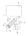
図8に従来の簡易硬水軟化装置300が示してある。この簡易硬水軟化装置300は円筒形のシリンダー90の下部を下部キャップ120で塞ぎ、イオン交換樹脂60をシリンダー90内最上部まで充填する。イオン交換樹脂60の上に、円柱形のスポンジ70を乗せ、シリンダー90の上面に通水用開口部を開けた図示しないキャップ形のスポンジ70押さえ板を通水用開口部側を上にしてスポンジ70にかぶせ、上部キャップ130で塞ぐ。上部キャップ130を塞ぐ場合、イオン交換樹脂60は最上部まで充填されているため、円柱形のスポンジ70は容器(シリンダー90)の長さ方向に圧縮される。
FIG. 8 shows a conventional simple
図8では、従来の簡易硬水軟化装置300の使用例のフローを示したものである。簡易硬水軟化装置300、給水タンク400、給水ポンプ50が設けられ、ボイラ100へ接続される給水配管200において、簡易硬水軟化装置300を斜め方向に設置しても、簡易硬水軟化装置300内に円柱形のスポンジ70を詰めているため、イオン交換樹脂60部分の境界はシリンダー90の開口面と平行になり、イオン交換樹脂60は円柱状のまま沈降する。簡易硬水軟化装置300内のスポンジ70側から通水された原水は円柱形の樹脂(イオン交換樹脂60)層を通過する際、硬度成分ナトリウム(Na)、カルシウム(Ca)、マグネシウム(Mg)及びシリカ等が取り除かれて軟水となりボイラ100へ給水される(特許文献1参照)。
In FIG. 8, the flow of the usage example of the conventional simple
しかしながら、上記のような簡単なフィルタータイプの装置では、軟水処理の効果があまり期待出来ないのが現状である。また、軟水処理装置は、原水にイオン交換樹脂を用いて物理化学的に処理するか、原水を物理的に濾過して処理するとか、さらに原水に熱処理を施して処理するというのが一般的である。しかしながら、処理能力、装置の大きさ、及びランニングコスト等を考慮すると、どれも高価なものにならざるを得ないというのが現状である。 However, with the simple filter type apparatus as described above, it is currently difficult to expect the effect of soft water treatment. In addition, it is common for soft water treatment equipment to treat raw water physicochemically using an ion exchange resin, to physically filter raw water, or to treat raw water by heat treatment. is there. However, in consideration of the processing capacity, the size of the apparatus, the running cost, etc., all of them are inevitably expensive.
また、各種電気分解整水生成装置において、浄水部は前処理として大きな役割を果たしているが、ほとんどの電気分解整水生成装置の浄水部は活性炭をベースにした浄水部となっており、活性炭を用いたフィルターには処理能力の限界があり、特に硬水での浄水には、活性炭を用いたフィルターの交換時期が早まるなどの現象が多く見られる。 Moreover, in various electrolyzed water purification devices, the water purification unit plays a major role as a pretreatment, but the water purification unit of most electrolyzed water purification devices is a water purification unit based on activated carbon. The filter used has a limit of treatment capacity, and in particular, in the case of purified water with hard water, there are many phenomena such as the replacement time of the filter using activated carbon being advanced.
本発明は、上記の事情に鑑みなされたものであり、原水の中に含まれる硬水成分であるNa、Ca、Mg等のイオンの除去機能と、原水の浄水機能とを持ち、原水の各種電気分解における前処理装置として働きをなす軟水化装置を提供することを目的とする。 The present invention has been made in view of the above circumstances, and has a function of removing ions such as Na, Ca and Mg, which are hard water components contained in raw water, and a function of purifying raw water. An object of the present invention is to provide a water softening device that functions as a pretreatment device for decomposition.
上記の目的を達成するために、請求項1に記載の発明は、容器に設けられ、液体である原水を前記容器の内部へ導くための入水口と、前記容器に設けられ、前記原水を前記容器内を循環した後に前記容器の外部へ導くための吐水口と、を備えた軟水化装置において、前記入水口から前記容器の内部へ供給された前記原水を電気分解するために前記容器の内部に設けられた電極部材と、前記電極部材である陽極部材と陰極部材との間に設けられ、電解隔膜となる第一フィルターと、前記入水口から供給された前記原水を通過させるために設けられ、前記陰極部材と隣り合って設けられた第二フィルターと、を備えることを特徴とする。
In order to achieve the above object, the invention according to
従って、請求項1に記載の発明によれば、水道水、或いは地下水を含めた原水を入水口から容器中で送り込むと、原水は第二フィルターを通り、第一フィルターを電解各隔膜として陰極部材と陽極部材とで原水の電気分解を行うと、原水の硬水成分であるカルシウム、マグネシウム、ナトリウム及びシリカ等のイオンは陰極部材側に吸着することが可能になる。 Therefore, according to the first aspect of the present invention, when raw water including tap water or ground water is fed into the container from the water inlet, the raw water passes through the second filter, and the first filter serves as an electrolytic membrane. When the raw water is electrolyzed with the anode member, ions such as calcium, magnesium, sodium and silica, which are hard water components of the raw water, can be adsorbed on the cathode member side.
また、請求項2に記載の発明は、請求項1に記載の構成に加え、前記第二フィルターは前記陰極部材と接触していることを特徴とする。
The invention according to
従って、請求項2に記載の発明によれば、陰極部材と第二フィルターとを接触させているため陰極部材に吸引される原水の硬水成分であるカルシウム、マグネシウム、ナトリウム及びシリカ等を第二フィルター内に吸着させることが可能になる。
Therefore, according to the invention described in
さらに、請求項3に記載の発明は、請求項1又は2に記載の構成に加え、前記第二フィルターはカーボンであることを特徴とする。
Furthermore, the invention described in
従って、請求項3に記載の発明によれば、第二フィルターをカーボンにすることで、原水を陰極部材と陽極部材とで電気分解を行ったときに第二フィルターも陰極部材の一部として働かすことが可能になり、原水の硬水成分であるカルシウム、マグネシウム、ナトリウム及びシリカ等を第二フィルター内に電気的に吸着させることが可能になるとともに、カルキ、カビ等の除去である浄水処理することも可能になる。
Therefore, according to the invention described in
また、請求項4に記載の発明は、請求項1乃至3のいずれかに記載の構成に加え、前記陰極部材は網目状の形状であることを特徴とする。 According to a fourth aspect of the present invention, in addition to the structure according to any one of the first to third aspects, the cathode member has a mesh shape.
従って、請求項4に記載の発明によれば、陰極部材は網目状の形状をなしているので、陰極部材の網目状(メッシュ状)に設けられている網目(隙間である孔)より小さい径の硬水成分であるカルシウム、マグネシウム、ナトリウム及びシリカ等でも陰極部材の網目状(メッシュ状)に設けられている網目(隙間である孔)内に吸着させることが可能になる。 Therefore, according to the invention described in claim 4, since the cathode member has a mesh shape, the diameter is smaller than the mesh (holes which are gaps) provided in the mesh shape (mesh shape) of the cathode member. It is possible to adsorb calcium, magnesium, sodium, silica, and the like, which are hard water components, into the mesh (mesh) provided in the mesh (holes) of the cathode member.
さらに、請求項5に記載の発明は、請求項1乃至4のいずれかに記載の構成に加え、前記第一フィルターは不織布であることを特徴とする。
Furthermore, in addition to the structure in any one of
従って、請求項5に記載の発明によれば、電解隔膜である第一フィルターに不織布を用いているので、原水の入水から吐水の圧力損失の変化を抑えることが可能になるとともに、原水を電気分解したときに金属イオン等の移動を容易にすることが可能になり、また、他の材料に比べ加工が容易であり、さらに製造コストを抑えることが可能である。 Therefore, according to the fifth aspect of the invention, since the nonwoven fabric is used for the first filter which is the electrolytic diaphragm, it is possible to suppress the change in the pressure loss of the discharged water from the input of the raw water, and the raw water is electrically When decomposed, metal ions and the like can be easily moved, and processing is easier than other materials, and the manufacturing cost can be further reduced.
また、請求項6に記載の発明は、請求項1乃至5のいずれかに記載の構成に加え、前記電極部材は、円筒形状をなし、前記陽極部材と前記陰極部材とのいずれか一方が他方を収納できるように、互いの外径が異なることを特徴とする。 According to a sixth aspect of the present invention, in addition to the configuration according to any of the first to fifth aspects, the electrode member has a cylindrical shape, and one of the anode member and the cathode member is the other. The outer diameters are different from each other so that they can be stored.
従って、請求項6に記載の発明によれば、電極部材である陽極部材及び陰極部材はいずれか一方が他方を収納することで重ね合わせて二重構造となるように、互いに円筒形状をなしているため、電極部材の長さ、大きさ(径)を自由に選択できることを可能にしている。
Therefore, according to the invention described in
さらに、請求項7に記載の発明は、請求項1乃至5のいずれかに記載の構成に加え、前記電極部材は、平板形状をなし、前記陽極部材と前記陰極部材とが互いに向き合う位置にあることを特徴とする。
Furthermore, in the invention described in claim 7, in addition to the structure described in any one of
従って、請求項7に記載の発明によれば、電極部材は平板形状をなしているので、電極部材にメッキ等の表面処理を行う場合にむらなく均一に行うことが可能になる。 Therefore, according to the seventh aspect of the invention, since the electrode member has a flat plate shape, it is possible to uniformly perform the surface treatment such as plating on the electrode member.
また、請求項8に記載の発明は、請求項1乃至7のいずれかに記載の構成に加え、前記容器に設けられた前記入水口及び前記吐水口には、前記容器同士を連結するための連結用パイプを取り付けることが可能であることを特徴とする。
Moreover, in addition to the structure in any one of
従って、請求項8に記載の発明によれば、容器の入水管及び吐水管に連結用パイプを取り付けることで容器同士の連結を図ることで、軟水化装置の連結が可能になり、処理すべき原水の量に応じて軟水化装置の大型化、小型化を図ることが可能になる。 Therefore, according to the eighth aspect of the present invention, the connection of the water softening devices can be achieved by connecting the containers to each other by attaching the connection pipes to the water intake pipe and the water discharge pipe of the container. The water softening device can be made larger and smaller depending on the amount of raw water.
本発明によれば、陰極部材と陽極部材との間にフィルターを挟み込んで前処理のための電気分解を行い、第二フィルター及び陰極部材の濾過機能により水道水等の原水中に含まれるカルキ、カビ臭等の除去である浄水処理をすることができるとともに、陰極側の陰極部材及び第二フィルターに強制的に硬水成分であるカルシウム(Ca)、マグネシウム(Mg)、ナトリウム(Na)及びシリカ等の各イオン(硬水成分)を吸着させることで原水より硬水成分を容易に取り除くことができる。 According to the present invention, a filter is sandwiched between a cathode member and an anode member to perform electrolysis for pretreatment, and the chlorine contained in raw water such as tap water by the filtration function of the second filter and the cathode member, Calcium water (Ca), magnesium (Mg), sodium (Na), silica, etc. that are hard water components can be forcedly applied to the cathode member and the second filter on the cathode side while being able to perform water purification treatment for removing mold odors, etc. The hard water component can be easily removed from the raw water by adsorbing each ion (hard water component).
また、本発明による軟水化装置は容器内に陽極部材と陰極部材、複数のフィルターを用いているのに過ぎないので装置全体の小型軽量化を図ることができ、各種の整水生成器等に本発明である軟水化装置を内蔵することもできる。 Further, the water softening device according to the present invention only uses an anode member, a cathode member, and a plurality of filters in the container, so that the entire device can be reduced in size and weight, and can be used for various water conditioners. The water softening device according to the present invention can also be incorporated.
以下、本発明を実施するための最良の形態について図面を参照して説明する。 The best mode for carrying out the present invention will be described below with reference to the drawings.
(例1)
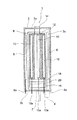
図1には、本発明である軟水化装置1の概略が示してある。本例で示す軟水化装置1の形状は、円筒形をなしているが、特に円筒形の形状に限定されるものではない。容器の形状をなしている軟水化装置1の本体部3には、入水口2及び吐水口4が設けられている。入水口2は、水道水、或いは地下水等を含めた原水を容器である本体部3内に導き入れるための入口であり、吐水口4は容器である本体部3内で本体部3内を循環させて原水を処理した後に、処理した原水を本体部3内から本体部3外へ導き出すための出口である。
(Example 1)
In FIG. 1, the outline of the water softening
本体部3内の内壁3cに沿って陽極部材8が複数設けられている。本例での陽極部材8は、棒状(板状)の形状をなしており板状(棒状)の陽極部材8が本体部3内の内壁に沿って取り付けられている。陽極部材8の一方の端部からは陽極用端子8aが延びており、容器である本体部3の一方の端面3bを突き出して延びている。本例では、陽極部材8として板状の形状のものを用いているが、容器である本体部3と同じような円筒状の形状の陽極部材8を用いることも可能である。円筒状の形状の陽極部材8を用いる場合は、容器である本体部3の内壁3cに沿って円筒状の形状の陽極部材8を組み込むことになる。それ故、複数の板状の陽極部材8を本体部3内の内壁3cに取り付ける場合に比べ容易に取り付けられることになる。
A plurality of
本体部3の中央には、第一フィルター6が配置されており、第一フィルター6は本体部3の端面3aに設けられた支持部材14で支持されている。このように一箇所での支持に限定されることなく、本体部の端面3a、3bで支持することも可能である。第一フィルター6は不織布であり、原水の入水から吐水の圧力損失の変化を抑えることが可能になる。また、不織布を用いることで原水を電気分解したときに金属イオン等の移動を容易にすることが可能になる、さらに、不織布は他の材料に比べ加工が容易であり、製造コストを抑えることが可能になっている。
A
第一フィルター6に隣り合って陰極部材10が複数設けられている。陰極部材10も陽極部材8と同様であり、棒状(板状)の形状のものを用いている。この陰極部材10も陽極部材8と同様に、陰極部材10の一方の端部からは陰極用端子10aが延びており、容器である本体部3の一方の端面3bを突き出して延びている。本例では、陰極部材10として棒状(板状)の形状のものを用いているが、陽極部材8と同様に、容器である本体部3と同じような円筒状の形状の陰極部材10を用いることも可能である。そして、この複数の陰極部材10はチタン材からなっている。この陰極部材10には網目状(メッシュ状)の網目(隙間である孔)を設けていない。ただし、陰極部材10に網目状(メッシュ状)にし、多数の網目(隙間である孔)を設けることも可能である。
A plurality of
本例では、この複数の陰極部材10は第二フィルター12内に収められている。第二フィルター12はカーボンからできており、網目状(メッシュ状)になっており、多数の網目(隙間である孔)が設けられている。このようにカーボンを用いることで、電気分解を行ったときに第二フィルター12も陰極部材10の一部として作用させることが可能になる。特に、本例においては、第二フィルター12と陰極部材10とが接触するように配置されている。それ故、カーボンを陰極部材10と共用して、カーボンをマイナスに帯電させることで電気化学的にプラスイオンである硬水成分であるカルシウム、マグネシウム、ナトリウム及びシリカ等の各イオンを吸着することが可能になる。
In this example, the plurality of
また、第二フィルター12の下方には、浄水用フィルター16、18が設けてあり、その浄水用フィルター16、18の間に水道水に含まれる塩素を吸着するための亜硝酸カルシウム層が設けられている。さらに、第二フィルター12の上方の支持部材14にはカルシウム添加剤が充填されている。
Further, below the
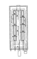
つぎに、以上の構成の軟水化装置1の動作について説明する。まず、水道水、或いは地下水等を含めた原水を軟水化装置1の入水口2へ供給する。入水口2へ供給された原水は、入水口2を通り浄水用フィルター16へ入っていく(図2に示す矢印A方向)。この部分では、原水に含まれている不用物等についての浄水処理が行われることになり、原水についての物理的な濾過が行われる。そして、この浄水用フィルター16を通り抜けた原水は亜硝酸カルシウム層20へ入っていく。亜硝酸カルシウム層20に入った原水は、ここで原水に含まれる塩素が吸収されて、浄水用フィルター18へ入っていき、はじめの浄水用フィルター16と同様に、物理的な濾過が行われる。
Next, the operation of the
そして、入水口2からは原水が供給され続けるので、図2に示す矢印A方向に沿って、原水は第二フィルター12内を流れる。このときには、図示しない電源より陰極用端子10a及び陽極用端子8aに電圧が加わり、陰極部材10及び陽極部材8に電圧が加わっている。そして、原水は、図2に示す矢印A方向である第二フィルター12内を流れると、第一フィルター6を電解隔膜として、陽極部材8と陰極部材10とにより電気分解される。そのために、図2に示す矢印B方向に沿って陽極部材8側へ流れる原水の部分(酸性水)と、陰極部材10側へ流れる原水の部分(アルカリ性水)に分かれる。
And since raw | natural water continues being supplied from the
そして、このようにして、原水に対して第一フィルター6を電解隔膜として陽極部材8と陰極部材10とにより電気分解が行われると、陰極部材10が収められている第二フィルター12は陰極部材10と接触しているため、マイナスに帯電する。また、原水中に存在する硬水成分であるカルシウム、マグネシウム、ナトリウム及びシリカ等はプラスイオンである。それ故、硬水成分であるカルシウム、マグネシウム、ナトリウム及びシリカ等は陰極部材10、或いは第二フィルター12に電気的に吸着する。
In this way, when electrolysis is performed on the raw water by the
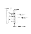
具体的な原理について、図3を用いて説明する。第二フィルター12内へ原水が供給されて、原水中に存在する硬水成分であるカルシウム、マグネシウム、ナトリウム及びシリカ等のうちでも第二フィルター12の網目状(メッシュ状)に設けられている孔径(隙間)より大きい径のものは第二フィルター12内にとどまる。そして、原水中に存在する硬水成分であるカルシウム、マグネシウム、ナトリウム及びシリカ等のうち第二フィルター12の網目状(メッシュ状)に設けられている孔径より小さい径のものは、本来物理的には第二フィルター12の孔や、隣接する陰極部材10同士の隙間をすり抜けてしまう。
A specific principle will be described with reference to FIG. When the raw water is supplied into the
しかしながら、陰極部材10及び第二フィルター12はマイナスに帯電しているため、プラスイオンである原水中に存在する硬水成分であるカルシウム、マグネシウム、ナトリウム及びシリカ等は陰極部材10及び第二フィルター12に吸引される。
However, since the
そして、原水中に存在する硬水成分であるカルシウム、マグネシウム、ナトリウム及びシリカ等のうち第二フィルター12の網目状(メッシュ状)に設けられている網目(隙間)より小さいものでも、第二フィルター12の網目状(メッシュ状)に設けられている網目(隙間)内や陰極部材10に吸着させられる。また、同時に原水が第二フィルター12を通過することにより、原水中に含まれるカルキ、カビ臭等の除去も第二フィルター12により行われ浄水処理も行われる。
And even if it is smaller than the mesh (gap) provided in the mesh shape (mesh shape) of the
そして、このように第二フィルター12内で原水から硬水成分であるカルシウム、マグネシウム、ナトリウム及びシリカ等が取り除かれることで硬水成分の濾過が行われると同時に原水中に含まれるカルキ、カビ臭等の除去である浄水処理も行われているときに、支持部材より原水にカルシウム添加剤の添加が行われる。
In addition, the hard water component is filtered by removing the hard water components such as calcium, magnesium, sodium and silica from the raw water in the
以上のように、硬水成分であるカルシウム、マグネシウム、ナトリウム及びシリカ等が取り除かれ、カルキ、カビ臭等の除去である浄水処理も行われた原水は、図2の矢印B方向に沿って、第二フィルター12を通り抜ける。そして、第二フィルター12を通り抜けた原水は、図2の矢印C方向に沿って、本体部3内の内壁3cに沿って設けられた陽極部材8に沿って流れる。最終的には、以上のように、硬水成分であるカルシウム、マグネシウム、ナトリウム及びシリカ等が取り除かれ、カルキ、カビ臭等の除去である浄水処理も行われた原水は、本体部3内を循環して、本体部3に設けられた吐水口4より、図3に示す処理水として、流れ出る。
As described above, raw water from which hard water components such as calcium, magnesium, sodium, and silica are removed and water purification treatment that is removal of calcite, mold odor, and the like is performed, is performed along the direction of arrow B in FIG. Pass through the
(例2)
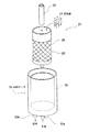
つぎに、本発明である軟水化装置の別の形態について説明する。図4に本発明である軟水化装置の別の形態が示されている。この軟水化装置21は円筒状の部材を組み合わせることより構成されている。円筒形状をなすABS樹脂である熱可塑性樹脂からなる容器(ケース)32には、原水を容器32の内部へ導くための入水口32aと、容器32内を循環した後に原水を容器32の外部へ導くための吐水口32bと、が容器32の端面に設けられている。
(Example 2)
Next, another embodiment of the water softening device according to the present invention will be described. FIG. 4 shows another embodiment of the water softening device according to the present invention. This
容器32の内部に組み込まれる陽極部材30及び陰極部材26は、円筒形状をなし、陽極部材30が陰極部材26を収納できるように、互いの外径が異なるように設定されている。具体的には、図4に示すように、容器32の内部には、円筒形状の陽極部材30が組み込まれている。本例においては容器30に組み込まれる前から円筒形状をなしている円筒形状の陽極部材30を用いている。ただし、円筒形状の陽極部材30は、容器32に組み込まれる前から円筒形状をなしている必要はなく、容器32に組み込むことで円筒形状をなす板状の陽極部材30であってもよい。
The
円筒形状の陽極部材30内には、円筒形状の陰極部材26が組み込まれることになる。この円筒形状の陰極部材26はチタン材からなり網目状(メッシュ状)になっており、多数の網目(隙間である孔)が設けられている。そして、この円筒形状の陰極部材26を覆うように、円筒形状の陰極部材26上には第一フィルター28が設けられている。
A
この円筒形状の陰極部材26内には、円筒形状の陰極部材26内(容器30内)に原水を導くための入水管22が入水口32aとつながるように設けられている。円筒形状の陰極部材26内の入水管22のまわりには第二フィルター24となる粒状、或いは紛状の活性炭が充填されている。
In the
以上の構成により、入水口32aから容器32に原水が供給され、図示しない電源より円筒形状の陽極部材30及び円筒形状の陰極部材26に電圧が加わり電気分解が行われると、原水は円筒形状の陰極部材26及び第二フィルター24である粒状、或いは紛状の活性炭により、硬水成分であるカルシウム、マグネシウム、ナトリウム及びシリカ等が取り除かれ、カルキ、カビ臭等の除去である浄水処理も行われて吐水口32bより容器32から流れ出ることになる。
With the above configuration, when raw water is supplied from the
そして、具体的には、原水に対して第一フィルター6を電解隔膜として陽極部材30と陰極部材26とにより電気分解が行われると、陰極部材26が収められている第二フィルター24は陰極部材26と接触しているため、マイナスに帯電する。また、原水中に存在する硬水成分であるカルシウム、マグネシウム、ナトリウム及びシリカ等はプラスイオンである。それ故、硬水成分であるカルシウム、マグネシウム、ナトリウム及びシリカ等は陰極部材26、或いは第二フィルター24に電気的に吸着する。
More specifically, when electrolysis is performed on the raw water by the
具体的な原理について、図3を用いて説明する。第二フィルター24内へ原水が供給されて、原水中に存在する硬水成分であるカルシウム、マグネシウム、ナトリウム及びシリカ等のうちでも第二フィルター24の孔径や陰極部材26の網目状(メッシュ状)に設けられている網目(隙間)より大きい径のものは第二フィルター24内に収まる。
A specific principle will be described with reference to FIG. The raw water is supplied into the second filter 24, and among the hard water components calcium, magnesium, sodium, and silica that are present in the raw water, the pore diameter of the second filter 24 and the mesh shape of the
そして、原水中に存在する硬水成分であるカルシウム、マグネシウム、ナトリウム及びシリカ等のうち第二フィルター24の孔径や陰極部材26の網目状(メッシュ状)に設けられている網目(隙間)より小さい径のものは、本来物理的には第二フィルター24の孔や陰極部材26の網目状(メッシュ状)に設けられている網目(隙間である孔)をすり抜けてしまう。
And the diameter smaller than the hole diameter of the 2nd filter 24 and the mesh | network (mesh shape) provided in the mesh | network shape (mesh shape) of the
しかしながら、陰極部材26及び第二フィルター24はマイナスに帯電しているため、プラスイオンである原水中に存在する硬水成分であるカルシウム、マグネシウム、ナトリウム及びシリカ等は陰極部材26及び第二フィルター24に吸引される。
However, since the
そして、原水中に存在する硬水成分であるカルシウム、マグネシウム、ナトリウム及びシリカ等のうち第二フィルター24の孔径や陰極部材26の網目状(メッシュ状)に設けられている網目(隙間)より小さい径のものでも、例えば、第二フィルター24の孔内や陰極部材26の網目状(メッシュ状)に設けられている網目(隙間)内に吸着させられる。また、同時に原水は第二フィルター24を通過することにより、原水中に含まれるカルキ、カビ臭等の除去も第二フィルター24により行われ浄水処理も行われる。
And the diameter smaller than the hole diameter of the 2nd filter 24 and the mesh | network (mesh shape) provided in the mesh | network shape (mesh shape) of the
(例3)
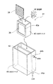
つぎに、本発明である軟水化装置の他の形態について説明する。図5に本発明である軟水化装置の別の形態が示されている。この軟水化装置31は箱形形状の部材を組み合わせることにより構成されている。箱形形状をなすABS樹脂である熱可塑性樹脂からなる容器(ケース)44には、原水を容器44の内部へ導くための入水口44aと、容器44内を循環した後に原水を容器30の外部へ導くための吐水口44bと、が容器44の端面に設けられている。
(Example 3)
Next, another embodiment of the water softening device according to the present invention will be described. FIG. 5 shows another embodiment of the water softening device according to the present invention. This
容器44の内部に組み込まれる陽極部材42及び陰極部材42は、平板形状をなし、陽極部材42と陰極部材24とが互いに向き合う位置になるように設定されている。本例においては、平板形状の陽極部材42は、容器44内を二つに仕切る仕切板のように、容器44の中央位置に設けられている(図5参照)。容器44内を等分に仕切る位置に平板形状の陽極部材42を設ける必要はなく、一方側を広く、他方側を狭くなるような位置に平板形状の陽極部材42を設けることも可能である。
The
容器44のいずれか側には、箱形形状をなすABS樹脂である熱可塑性樹脂からなる容器(ケース)40が組み込まれることになる。この容器40の、平板形状の陽極部材42と向かい合う、一方の側面部には孔部40aが設けられており、その孔部40aに第一フィルター36である平板形状の不織布が貼付してある。そして、容器40の内部より、第一フィルター36である平板形状の不織布と接触して平板形状の陰極部材34が設けられている。この平板形状の陰極部材26はチタン材からなり網目状(メッシュ状)になっており、多数の網目(隙間である孔)が設けられている。
On either side of the
そして、この容器40は、容器44の入水管44aとつながっており、入水口44aから原水が供給されると容器40内に原水が供給されるようになっている。
この容器40内には、平板形状の陰極部材26と隣接して第二フィルター38となる粒状、或いは紛状の活性炭が充填されている。
And this
The
以上の構成により、軟水化装置31は、例1及び例2に示す軟水化装置1、21と同様の動作を行うことになる。つまり、入水口44aから容器44に原水が供給され、図示しない電源より平板形状の陽極部材42及び平板形状の陰極部材34に電圧が加わり電気分解が行われると、原水は平板形状の陰極部材34及び第二フィルター38である粒状、或いは紛状の活性炭により、硬水成分であるカルシウム、マグネシウム、ナトリウム及びシリカ等が取り除かれ、カルキ、カビ臭等の除去である浄水処理も行われて、吐水口44bより容器44から流れ出ることになる。
With the above configuration, the
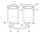
また、処理すべき原水の量によっては、単体の軟水化装置1、21、31では十分に対処しきれない場合がある。その場合には、軟水化装置1、21、31を連結することになる。具体的な、軟水化装置21、31の連結を図6及び図7を用いて説明する。図6では、円筒形状をなす陽極部材30及び陰極部材26を組み込んだ軟水化装置21の連結について示してある。図6に示す一方の軟水化装置21aの容器32の吐水口32bと他方の軟水化装置21bの容器32の入水口32aとが連結用パイプ46で連結してある。
Further, depending on the amount of raw water to be treated, the single
また、図6に示す一方の軟水化装置21aの容器32の入水口32aと図示しない軟水化装置21の容器32の吐水口32bとが連結用パイプ46で連結してある。さらに、図6に示す他方の軟水化装置21の容器32の吐水口32bと図示しない軟水化装置21の容器32の入水口32aとが連結用パイプ46で連結してある。以上のように、軟水化装置21の容器32を連結用パイプ46を用いて複数連結することにより、処理すべき原水の量が大量であっても短時間で硬水成分であるカルシウム、マグネシウム、ナトリウム及びシリカ等を取り除くことができるとともに、カルキ、カビ臭等の除去である浄水処理も行うことができる。
Further, a
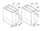
さらに、図7では、図5に示す平板形状をなす陽極部材42と陰極部材24とを用いる軟水化装置31の連結について示してある。図7に示す一方の軟水化装置31aの容器44の吐水口44bと他方の軟水化装置31bの容器44の入水口44aとが連結用パイプ48で連結してある。
Further, FIG. 7 shows the connection of the
また、図7に示す一方の軟水化装置31aの容器44の入水口44aと図示しない軟水化装置31bの容器44の吐水口44bとが連結用パイプ48で連結してある。さらに、図7に示す他方の軟水化装置31bの容器44の吐水口44bと図示しない軟水化装置31の容器44の入水口44aとが連結用パイプ48で連結してある。以上のように、軟水化装置31の容器44を連結用パイプ48を用いて複数連結することにより、図6に示す軟水化装置21の連結の場合と同様に、処理すべき原水の量が大量であっても短時間で硬水成分であるカルシウム、マグネシウム、ナトリウム及びシリカ等を取り除くことができるとともに、カルキ、カビ臭等の除去である浄水処理も行うことができる。
Further, the
1、21、31…軟水化装置、2、32a、44a…入水口、3、32、44…本体部(容器)、4、32b、44b…吐水口、6、28、36…第一フィルター、8、30、42…陽極部材、10、26、34…陰極部材、12、24、38…第二フィルター、14…支持部材、16…浄水用フィルター、18…浄水用フィルター、20…亜硝酸カルシウム、46、48…連結用パイプ
1, 21, 31 ... water softening device, 2, 32a, 44a ... water inlet, 3, 32, 44 ... main body (container) 4, 32b, 44b ... water outlet, 6, 28, 36 ... first filter, 8, 30, 42 ... anode member, 10, 26, 34 ... cathode member, 12, 24, 38 ... second filter, 14 ... support member, 16 ... filter for water purification, 18 ... filter for water purification, 20 ... calcium nitrite , 46, 48 ... Pipe for connection
Claims (8)
前記入水口から前記容器の内部へ供給された前記原水を電気分解するために前記容器の内部に設けられた電極部材と、
前記電極部材である陽極部材と陰極部材との間に設けられ、電解隔膜となる第一フィルターと、
前記入水口から供給された前記原水を通過させるために設けられ、前記陰極部材と隣り合って設けられた第二フィルターと、を備えることを特徴とする軟水化装置。 A water inlet provided in the container for guiding the raw water, which is liquid, to the inside of the container; a water outlet provided in the container for guiding the raw water to the outside of the container after circulating in the container; In the water softening device comprising
An electrode member provided inside the container for electrolyzing the raw water supplied from the water inlet into the container;
A first filter provided between the anode member and the cathode member, which are the electrode members, and serving as an electrolytic diaphragm;
A water softening device comprising: a second filter provided to allow the raw water supplied from the water inlet to pass therethrough and provided adjacent to the cathode member.
8. The connection pipe for connecting the containers to each other can be attached to the water inlet and the water outlet provided in the container. Water softener.
Priority Applications (1)
| Application Number | Priority Date | Filing Date | Title |
|---|---|---|---|
| JP2004118037A JP2005296844A (en) | 2004-04-13 | 2004-04-13 | Water softener |
Applications Claiming Priority (1)
| Application Number | Priority Date | Filing Date | Title |
|---|---|---|---|
| JP2004118037A JP2005296844A (en) | 2004-04-13 | 2004-04-13 | Water softener |
Publications (1)
| Publication Number | Publication Date |
|---|---|
| JP2005296844A true JP2005296844A (en) | 2005-10-27 |
Family
ID=35329037
Family Applications (1)
| Application Number | Title | Priority Date | Filing Date |
|---|---|---|---|
| JP2004118037A Pending JP2005296844A (en) | 2004-04-13 | 2004-04-13 | Water softener |
Country Status (1)
| Country | Link |
|---|---|
| JP (1) | JP2005296844A (en) |
Cited By (1)
| Publication number | Priority date | Publication date | Assignee | Title |
|---|---|---|---|---|
| CN103723796A (en) * | 2012-12-28 | 2014-04-16 | 肖英 | Cyclic bathing and swimming water purifier |
-
2004
- 2004-04-13 JP JP2004118037A patent/JP2005296844A/en active Pending
Cited By (2)
| Publication number | Priority date | Publication date | Assignee | Title |
|---|---|---|---|---|
| CN103723796A (en) * | 2012-12-28 | 2014-04-16 | 肖英 | Cyclic bathing and swimming water purifier |
| CN103723796B (en) * | 2012-12-28 | 2016-04-20 | 肖英 | Swimming bath Water circulation purifier |
Similar Documents
| Publication | Publication Date | Title |
|---|---|---|
| Dong et al. | Selective removal of lead ions through capacitive deionization: Role of ion-exchange membrane | |
| KR101949540B1 (en) | Water treatment using a bipolar membrane | |
| KR101842552B1 (en) | Electrolytic Carbon Filter and Equipment of Water Treatment using the same | |
| JP6395952B1 (en) | Water treatment apparatus and water treatment method | |
| KR101373389B1 (en) | On-site sodium hypochlorite generator for high concentration product | |
| WO2015165234A1 (en) | Method for decontamination treatment and utilization as resource of ion exchange resin desorption solution | |
| WO2017122520A1 (en) | Water treatment device and water treatment method | |
| CN101891331A (en) | Activated carbon adsorption and electrochemical regeneration integrated treatment device and using method thereof | |
| KR102168891B1 (en) | Equipment of Advanced Wastewater Treatment using Eletrolysis-adsorption filtration | |
| KR101407728B1 (en) | a water purifier | |
| CN201942590U (en) | Water purifier for bath | |
| US20230031927A1 (en) | Faradic porosity cell | |
| US20230009842A1 (en) | Faradic porosity cell | |
| JP2005296844A (en) | Water softener | |
| US11795073B2 (en) | Electrocoagulation device | |
| KR200356986Y1 (en) | Handy filter for creation of alkaliwater | |
| KR200445058Y1 (en) | Ion water generation cartridge for water purifier | |
| JP2005013862A (en) | Water modifying device | |
| JP5634759B2 (en) | Fluorine removal method and fluorine removal system | |
| KR20160114499A (en) | A water purifier provided with a resin wash unit | |
| CN207227165U (en) | The combined system of chlorion deep purifying in a kind of tap water | |
| CN224062594U (en) | Multi-functional drinking water multi-medium filter | |
| KR20160047934A (en) | Apparatus and method for treating graywater | |
| JP2007017087A (en) | refrigerator | |
| US20200062618A1 (en) | Pollutant removing system for water treatment |