JP2005296796A - Method and apparatus for cleaning sewage flow passage - Google Patents
Method and apparatus for cleaning sewage flow passage Download PDFInfo
- Publication number
- JP2005296796A JP2005296796A JP2004116626A JP2004116626A JP2005296796A JP 2005296796 A JP2005296796 A JP 2005296796A JP 2004116626 A JP2004116626 A JP 2004116626A JP 2004116626 A JP2004116626 A JP 2004116626A JP 2005296796 A JP2005296796 A JP 2005296796A
- Authority
- JP
- Japan
- Prior art keywords
- sewage
- hydrogen sulfide
- electromagnetic wave
- flow path
- coil
- Prior art date
- Legal status (The legal status is an assumption and is not a legal conclusion. Google has not performed a legal analysis and makes no representation as to the accuracy of the status listed.)
- Granted
Links
Images

Landscapes
- Removal Of Specific Substances (AREA)
- Water Treatment By Electricity Or Magnetism (AREA)
Abstract
Description
本発明は、変調電磁波処理及び硫化水素抑制剤併用による下水流路内で硫化水素の生成を抑制する下水流路内の浄化方法と装置に関する。 The present invention relates to a purification method and apparatus in a sewage flow path that suppresses generation of hydrogen sulfide in a sewage flow path by using a modulated electromagnetic wave treatment and a hydrogen sulfide inhibitor in combination.
日本など山間部の多い国土では、下水流路内を流れる下水を一旦中継ポンプピットに溜めた後、登り流路をポンプで圧送して下水処理場に送る必要がある。この下水の圧送前の中継ポンプピット内において下水が長時間滞留して嫌気的な状態になると硫酸イオンが嫌気性細菌(硫酸塩還元細菌)によって還元され、硫化物が生成される。中継ポンプピット内で発生した硫化物は圧送先のマンホール又は着水井などの吐き出し部分で硫化水素ガスとして放散される。この硫化水素ガスは悪臭原因のひとつでもあるが、気相への放散個所において好気性細菌である硫黄酸化細菌によって硫化水素から硫酸が生成される。マンホール又は着水井を構成するコンクリート製施設は、前記下水から生成された硫酸によって腐食を生ずる問題が発生している。 In a country with many mountainous areas such as Japan, it is necessary to collect the sewage flowing in the sewage channel once in the relay pump pit and then pump the climbing channel with a pump to send it to the sewage treatment plant. When the sewage stays in the relay pump pit before the sewage is pumped for a long time and becomes anaerobic, sulfate ions are reduced by anaerobic bacteria (sulfate-reducing bacteria), and sulfide is generated. Sulfide generated in the relay pump pit is diffused as hydrogen sulfide gas at the discharge port such as a manhole or a landing well of a pumping destination. Although this hydrogen sulfide gas is one of the causes of bad odor, sulfuric acid is produced from hydrogen sulfide by sulfur-oxidizing bacteria, which are aerobic bacteria, at the point of release to the gas phase. A concrete facility that constitutes a manhole or a landing well has a problem of being corroded by sulfuric acid generated from the sewage.
このような 下水流路内で発生する硫化物の抑制のための技術として、従来は次のような対策が講じられていた。
(1)酸素供給法(空気又は酸素の注入法)
汚水と空気を一緒に流す事で下水を好気性条件下に保持し、硫化物の生成を抑制する方法である。
Conventionally, the following measures have been taken as a technique for suppressing sulfides generated in such sewage channels.
(1) Oxygen supply method (air or oxygen injection method)
This is a method of maintaining the sewage under aerobic conditions by flowing sewage and air together and suppressing the formation of sulfides.
(2)薬品添加法
薬品を添加して硫化物の固定化と下水の嫌気化などの防止を行う。前記硫化物の固定化と下水の嫌気化には塩化第二鉄、硫酸第一鉄、硝酸塩、過酸化水素、塩素又は水酸化ナトリウムなどの薬品が用いられる。
(2) Chemical addition method
Add chemicals to fix sulfides and prevent anaerobic sewage. Chemicals such as ferric chloride, ferrous sulfate, nitrate, hydrogen peroxide, chlorine or sodium hydroxide are used for fixing the sulfide and anaerobic sewage.
(3)施設の防食法
耐食性材料、塗装及びライニング等の処置により施設の劣化防止を行う。
(3) Anticorrosion method for facilities
Prevent deterioration of facilities by measures such as corrosion resistant materials, painting and lining.
(4)管路清掃法
管路を高流速体で洗浄し、排泥する方法であり、ピグ洗浄法等がある。
This is a method of washing the pipe with a high flow velocity body and discharging the mud, such as a pig washing method.
前記(1)の酸素供給法には次のような問題点がある。
(a)イニシャルコストが大きく、保守点検と不具合発生を常に考慮しなければならず、予備機を設置すると更にコストが大きい。
The oxygen supply method (1) has the following problems.
(A) The initial cost is high, maintenance inspection and occurrence of defects must always be taken into consideration, and the cost is further increased when a spare machine is installed.
(b)下水を圧送するために下水流路内の中継ポンプピット内に設けられた圧送ポンプの停止時も常に中継ポンプピット内に空気注入を連続して行うことで、下水を好気性条件下に保持する必要がある。このためのランニングコストとしてコンプレッサー電力費及び圧送ポンプ電力費増加分が加算される。また下水と共に空気を送るために酸素の実質の圧送量が低下し、圧送ポンプ稼働時間が増加する分が加算される。 (B) By continuously injecting air into the relay pump pit even when the pumping pump provided in the relay pump pit in the sewage flow path is stopped to pump the sewage, Need to hold on. As the running cost for this, the compressor power cost and the increase in the pumping pump power cost are added. Moreover, since air is sent together with sewage, the substantial pumping amount of oxygen is reduced, and an increase in the pumping pump operating time is added.
(c)圧送ポンプの変更を伴う場合がある。空気注入による圧力損失が伴う場合は既設圧送ポンプを変更する必要があり、これが設備コストの増加分となる。 (C) There is a case where the pumping pump is changed. When pressure loss due to air injection is accompanied, it is necessary to change the existing pumping pump, which increases the equipment cost.
(d)下り勾配部を避けて圧送管路設計又は圧送管路変更を必要とするため、該管路内に空気を注入することによる圧力損失は下り勾配が大きい程、大きいため、これを考慮した圧送管路設計又は既設管路に対しては変更を必要とする。 (D) Since it is necessary to design the pumping pipeline or change the pumping pipeline while avoiding the downward gradient portion, the pressure loss caused by injecting air into the pipeline is larger as the downward gradient is larger. It is necessary to make changes to the pumping pipeline design or existing pipelines.
(e)圧送先の下水流路の途中に設ける複数の流入部を有するマンホールでは逆流防止策が必要である。また、多重圧送の場合も同様である。 (E) In the manhole having a plurality of inflow portions provided in the middle of the sewage flow path at the pressure destination, a backflow prevention measure is required. The same applies to multiple pumping.
(f)空気注入を行っている下水流路において配管の破損する場合又は継ぎ手が抜ける場合、配管内の圧縮空気の残留分が外部に飛散するおそれがある。
以上のように空気注入方式では数々の制約が伴い、対策として問題が多い。
(F) In the case where the pipe is damaged or the joint comes off in the sewage flow channel in which air is being injected, there is a possibility that the remaining compressed air in the pipe will be scattered outside.
As described above, the air injection method has many limitations and has many problems as countermeasures.
(2)前記薬品添加法では硫化物の固定化、嫌気化防止等のために次のような問題点がある。
(a)鉄成分を注入する場合に硫化鉄の固定化には多量の薬剤を必要とする。汚水性状又は下水流路条件にも左右されるが、300〜500ppm近い薬品注入率を要する箇所もある。また、生成する鉄水酸化物の比重が大きく、下水処理領域の後段の管路内に堆積し易い。さらに、下水排出基準の溶解性鉄濃度は10ppm以下と定められている事から当該下水流路における適用は困難である。
(2) The above chemical addition method has the following problems in order to fix sulfides and prevent anaerobic formation.
(A) When an iron component is injected, a large amount of drug is required to fix iron sulfide. Although it depends on the state of sewage or the sewage flow path, there are some places that require a chemical injection rate close to 300 to 500 ppm. Moreover, the specific gravity of the iron hydroxide to be generated is large, and it is easy to deposit in the pipeline at the rear stage of the sewage treatment area. Furthermore, since the soluble iron concentration of the sewage discharge standard is determined to be 10 ppm or less, it is difficult to apply in the sewage flow path.
(b)硝酸塩は硫酸塩還元反応の抑制を目的に使用される。しかし昨今のN(窒素)・P(リン)排出量削減の気運からも好ましい添加薬品とは言えない。また、その添加効果もあまりない。 (B) Nitrate is used for the purpose of inhibiting the sulfate reduction reaction. However, it cannot be said that it is a preferable additive chemical from the recent trend of reducing N (nitrogen) and P (phosphorus) emissions. Moreover, there is not much addition effect.
(c)過酸化水素は汚水の嫌気化防止及び硫化物の酸化を目的として使用される。しかし、過酸化水素は下水のORP(酸化還元電位)を上げるためには多量の酸化剤(過酸化水素)を要するので、二次公害の原因となり易い。 (C) Hydrogen peroxide is used for the purpose of preventing the anaerobization of sewage and oxidizing sulfides. However, since hydrogen peroxide requires a large amount of oxidizing agent (hydrogen peroxide) in order to increase the ORP (redox potential) of sewage, it is likely to cause secondary pollution.
(d)塩素は殺菌及び硫化物の酸化を目的として使用される。この場合も、過酸化水素を添加する場合と同様に下水に対して多量の薬剤投入を必要とし、下水流路の金属部の腐食の問題及び多量に注入した場合の下水処理設備への影響等が問題となる。 (D) Chlorine is used for the purpose of sterilization and sulfide oxidation. In this case as well, as with the addition of hydrogen peroxide, a large amount of chemicals must be added to the sewage, the problem of corrosion of the metal part of the sewage flow path, and the impact on the sewage treatment facility when a large amount of injection is made. Is a problem.
(e)水酸化ナトリウムは「バイオフィルム」と呼ばれる下水流路内壁に付着する物質の不活性化を目的に使用されているが、実際には油分付着物を強アルカリで溶解させて除去又は付着防止する作用が主体となる。強アルカリ性であるために下水水質、特に下水のpHを大きく変化させるため、好ましい薬品ではない。
以上、薬品添加方式ではランニングコストが高く、水質変動を伴うものが多く、実用化が困難である。
(E) Sodium hydroxide is used to inactivate substances adhering to the inner wall of the sewage flow channel called “biofilm”, but in reality it is removed or adhered by dissolving oil deposits with strong alkali. The main effect is to prevent it. Since it is strongly alkaline, it greatly changes the quality of sewage water, particularly the pH of sewage, so it is not a preferred chemical.
As described above, the chemical addition method has a high running cost, often involves water quality fluctuations, and is difficult to put into practical use.
(3)施設の防食法は、多大のコストを要することと既存設備に対して補修する必要があるので推奨できない。
(4)下水流路清掃法は、定期的に多大のコストを要する作業が必要となる。
(3) The anticorrosion method for facilities cannot be recommended because it requires a great deal of cost and requires repairs to existing equipment.
(4) The sewage channel cleaning method requires work that requires a great deal of cost on a regular basis.
本発明の課題は、上記従来技術の問題点を解決し、硫化水素によるコンクリート腐食を防止し、かつ下水流路内で発生する硫化物の抑制させる方法と装置を提供することである。 An object of the present invention is to solve the above-mentioned problems of the prior art, to provide a method and apparatus for preventing concrete corrosion due to hydrogen sulfide and suppressing sulfides generated in a sewage flow path.
本発明の上記課題は次の解決手段により解決される。
請求項1記載の発明は、(−)帯電型変調電磁波発生器から10Hz〜1MHzの帯域で周波数が時間的に変化する交流電流をコイル部に流して、該コイル部が浸漬された下水内又は前記コイル部が配置された部位の近傍にある下水を電磁波処理し、同時に該下水に硫化水素抑制剤を供給する下水流路の浄化方法である。
The above-described problems of the present invention are solved by the following solution means.
According to the first aspect of the present invention, an alternating current whose frequency changes temporally in a band of 10 Hz to 1 MHz is caused to flow from the (−) charged modulated electromagnetic wave generator to the coil portion, and the sewage in which the coil portion is immersed or This is a method for purifying a sewage flow path in which sewage in the vicinity of the portion where the coil portion is disposed is subjected to electromagnetic wave treatment, and at the same time, a hydrogen sulfide inhibitor is supplied to the sewage.
請求項2記載の発明は、前記硫化水素抑制剤を下水流路の中で登り流路の手前に設置される中継ポンプピット内に一時的に貯留される下水内に添加する請求項1記載の下水流路の浄化方法である。 According to a second aspect of the present invention, the hydrogen sulfide inhibitor is added to sewage temporarily stored in a relay pump pit installed in front of the climbing channel in the sewage channel. This is a method for purifying a sewage channel.
請求項3記載の発明は、前記硫化水素抑制剤として、亜鉛又はニッケル成分を含有する金属塩を用いる請求項1又は2記載の下水流路の浄化方法である。
Invention of
請求項4記載の発明は、下水中の硫化水素濃度及び/又は下水流路内での下水の流速に応じて前記硫化水素抑制剤の注入量を調節する請求項1ないし3のいずれかに記載の下水流路の浄化方法である。 According to a fourth aspect of the present invention, the injection amount of the hydrogen sulfide inhibitor is adjusted according to the concentration of hydrogen sulfide in sewage and / or the flow rate of sewage in the sewage flow path. It is the purification method of a sewage flow path.
請求項5記載の発明は、下水流路内を流れる下水の電磁波処理用コイル部と該コイル部に10Hz〜1MHzの帯域で周波数が時間的に変化する交流電流を流す(−)帯電型変調電磁波発生器とを備えた変調電磁波処理装置と、下水流路内を流れる下水に硫化水素抑制剤を供給する硫化水素抑制剤供給装置を備えた下水流路の浄化装置である。 According to the fifth aspect of the present invention, there is provided a coil part for electromagnetic wave treatment of sewage flowing in the sewage flow path, and a negative (−) charged modulation electromagnetic wave in which an alternating current whose frequency changes temporally in a band of 10 Hz to 1 MHz is passed through the coil part. A purification apparatus for a sewage flow path including a modulated electromagnetic wave processing device including a generator and a hydrogen sulfide inhibitor supply device that supplies a hydrogen sulfide inhibitor to sewage flowing in the sewage flow path.
請求項6記載の発明は、変調電磁波処理装置のコイル部が、下水流路の中で登り流路の手前に設置される下水の一時的な貯留槽である中継ポンプピット内の下水内に浸漬して配置されるか又は前記中継ポンプピットの近傍に配置される請求項5記載の下水流路の浄化装置である。
In the invention according to
請求項7記載の発明は、下水流路には該流路内を流れる下水の流速計及び/又は硫化水素濃度計を設け、前記流速計の測定した下水流速及び/又は前記濃度計の測定した下水中の硫化水素濃度に応じて前記硫化水素抑制剤供給装置からの硫化水素抑制剤の供給量を調整する制御装置を設けた請求項5又は6記載の下水流路の浄化装置である。
According to the seventh aspect of the present invention, a sewage flow velocity and / or a hydrogen sulfide concentration meter that flows in the sewage flow channel is provided in the sewage flow channel, and the sewage flow velocity measured by the flow velocity meter and / or the concentration meter is measured. The sewage flow path purification device according to
請求項8記載の発明は、変調電磁波処理装置のコイル部が、(a)下水が流れる流路の表面に巻き付けたコイル、(b)下水中に浸漬したコイル設置部材表面に巻き付けたコイル又は(c)下水が流れる流路の近傍に配置したコイル設置部材表面に巻き付けたコイルからなる請求項5ないし7のいずれかに記載の下水流路の浄化装置である。
The invention according to
下水に混入した油分と水中の金属成分(Ca・Mg等)との反応により生成した金属セッケンは下水流路の内壁面へスケールとして付着し易い。 Metal soap produced by the reaction between the oil mixed in the sewage and the metal components (Ca, Mg, etc.) in the water easily adheres as a scale to the inner wall surface of the sewage channel.
請求項1、5記載の発明によれば、(−)帯電型変調電磁波処理により前記下水流路の内壁面へのスケール付着を防止する。しかし、(−)帯電型変調電磁波処理で、下水流路内壁等へのスケールの付着を防止できても粘着性付着物の形成が避けられない。前記粘着性付着物は腐敗すると硫化水素を発生し、硫化水素が水中に溶解してくる。そこで(−)帯電型変調電磁波処理をしているときに、同時に硫化水素抑制剤を下水中に添加して硫化水素の発生を抑制させる。
According to invention of
こうして、請求項1、5記載の発明によれば、硫化水素抑制剤などの薬品添加は最小限にとどめ、特別な新たな設備を取り付けること無く既存の下水施設を用いての浄化処理が可能となり、設備コストの負担がない。 Thus, according to the first and fifth aspects of the present invention, the addition of chemicals such as a hydrogen sulfide inhibitor is kept to a minimum, and purification using existing sewage facilities is possible without installing special new equipment. There is no burden of equipment costs.
請求項2、6記載の発明によれば、硫化水素抑制剤を下水流路の中で登り流路の手前に設置される中継ポンプピット内に一時的に貯留される下水内に添加することにより、貯留中の下水からの硫化水素発生量を抑制することができる。
According to invention of
請求項3記載の発明によれば、前記硫化水素抑制剤として亜鉛又はニッケル成分を含有する金属塩を用いることで硫化水素の発生を効果的に、しかも比較的低コストで抑制できる。
According to invention of
請求項4、7記載の発明によれば、前記硫化水素抑制剤を下水中の硫化水素濃度に応じて注入量を調節することで、過不足無く硫化水素抑制剤を使用できる。また、下水流路を流れる下水の流速により、下水流路内壁への粘着物の付着度合い又は中継ポンプピットから下水流路の登り流路へ下水を圧送するポンプ性能の劣化度合いが分かるので、硫化水素抑制剤の注入量を調節して効果的に下水流路の浄化ができる。
According to invention of
請求項8記載の発明によれば、変調電磁波処理装置のコイル部を下水貯留部の壁面へのスケール付着防止に最も効果的な部位に設けることで下水流路を浄化することができる。 According to the eighth aspect of the present invention, the sewage flow path can be purified by providing the coil part of the modulated electromagnetic wave processing device at the site most effective for preventing the scale from adhering to the wall surface of the sewage storage part.
本発明の実施の形態について図面と共に説明する。
以下、変調電磁波処理及び硫化水素抑制剤の併用システムについて説明する。
Embodiments of the present invention will be described with reference to the drawings.
Hereinafter, a combined electromagnetic wave treatment and hydrogen sulfide inhibitor combined system will be described.
(1)変調電磁波処理
図1に本実施例の下水処理システムの概略構成図を示し、図2には電磁波付与部の構成図を示す。
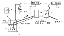
起伏の多い日本のような地形では下水配管から下水処理場に下水を搬送する過程で登り流路がある場合が多いので、一旦下水を中継ポンプピット1に貯留して、該中継ポンプピット1からポンプ5を用いて登り流路である下水圧送管路7内に下水を圧送する必要がある。
(1) Modulated electromagnetic wave processing
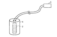
FIG. 1 shows a schematic configuration diagram of a sewage treatment system of the present embodiment, and FIG. 2 shows a configuration diagram of an electromagnetic wave application unit.
In terrain such as Japan with many undulations, there are many climbing channels in the process of transporting sewage from the sewage pipes to the sewage treatment plant, so the sewage is once stored in the
本実施例では前記下水中継ポンプピット1内にコイル部2を内蔵した電磁波付与部4を浸漬させる投げ込み式変調電磁波処理装置を用いて電磁波処理を行い、下水中継ポンプピット1内及び圧送管路7内における壁面に油分等のスケールが付着するのを防止する。
In this embodiment, the electromagnetic wave treatment is performed by using a throwing-type modulated electromagnetic wave treatment device in which the electromagnetic
(−)帯電型変調電磁波処理装置を用いて下水より混入する油分などの固着を防止することで下水圧送配管吐き出し側マンホール6における発生硫化水素を抑制させる。 下水に混入する油分は水中の金属成分(Ca・Mg等)との反応により金属セッケンを形成する。この際、界面活性剤の存在は金属セッケンの形成を促し易い。上記下水に混入する油分の固着防止用に用いる(+)帯電型界面活性剤と(−)帯電型界面活性剤を比較すると、(+)帯電型界面活性剤の方が金属セッケンを形成し易い。下水中継ポンプピット等では滞留によりマッドボールと呼ばれる油分の塊を生じたり、壁面への付着を生じている。また、下水圧送管路の内壁にも油分の付着を生じ易い。
(-) The hydrogen sulfide generated in the sewage pumping pipe discharge-
すなわち、下水槽壁面又は下水流路の配管内壁面に油分を主体とした付着物を生ずる場合、その付着物に共存する硫酸イオンは内部の嫌気性細菌(硝酸塩還元細菌)によって還元され、硫化物を形成し易い。付着物量が増加し、下水流量の少ない時間帯では滞留時間が長い程、硫化物濃度が増加し易い。流量増加に伴い、下水の吐き出し側マンホールにおける発生硫化水素濃度も増加する。 That is, when deposits mainly composed of oil are generated on the wall surface of the sewage tank or the pipe wall of the sewage flow channel, sulfate ions coexisting in the deposits are reduced by the anaerobic bacteria (nitrate-reducing bacteria) and sulfides. Is easy to form. The amount of deposits increases, and the sulfide concentration tends to increase as the residence time increases in the time zone where the sewage flow rate is small. As the flow rate increases, the generated hydrogen sulfide concentration in the manhole on the sewage discharge side also increases.
下水が流入する中継ポンプピット1内の下水内に変調電磁波処理装置のコイル部2を内蔵した電磁波付与部4を浸漬させる。該電磁波付与部4となるコイル部2には変調電磁波発生器3から時間の経過と共に周波数が変わる電流が流れる。この電流により形成される電磁波により下水が処理される。
An electromagnetic
通常、コイル部2は被処理水が流れる配管(図示せず)の外側へコイルを巻き付ける構成が採用され、該コイル2部へ(−)帯電型変調電磁波発生器3から変調電磁波を流すとコイル部2より発生する変調電磁波が前記配管を透過して被処理水に照射される。しかし、前記配管の材質によっては電磁波の透過量が異なり、ステンレス管<鋼鉄管<塩化ビニル管の順に電磁波透過量は多くなる。透過率の悪い材質に対してはコイル電流値を増加させて被処理水に必要な変調電磁波量を確保する。
Normally, the
そこで、本実施例では図2に示すように、コイル部2を絶縁性の合成樹脂製のケース(電磁波付与部)4内に密封して中継ポンプピット1内の下水中に浸漬した投込み照射型の装置を用いた。中継ポンプピット1内の下水内に投げ込む方式のコイル部2は、被処理水配管にコイルを巻く方法(図示せず)と比較して配管の材質に左右されないで電磁波を被処理水に有効に作用させることができる。また、図2に示すように下水中に投込み照射型の変調電磁波装置のコイル部2を浸漬させておくと、変調電磁波発生器3から発する変調電磁波エネルギーは全て被処理水に供給されるのでエネルギーのロスがない。
Therefore, in this embodiment, as shown in FIG. 2, the
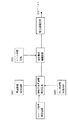
図3に(−)帯電型変調電磁波発生器3の構成を示す。図3において、スイープ信号発振回路から連続可変周波数発生回路にスイープ信号が所定時間間隔で発振され、周波数が変化しながら波形整形増幅回路に出力される。このとき連続可変周波数発生回路には周波数幅設定回路と中心周波数設定回路からの出力が入り、それぞれ周波数の幅の中心周波数が設定される。波形整形増幅回路では、レベル設定回路で電磁波強度を設定し、その後、電力増幅回路で適切な大きさの電力を得てコイル部2に出力する。
FIG. 3 shows the configuration of the (−) charged modulation
なお、電磁波強度とは空間における電磁波の強さを意味し、単位は[V/m]又は[A/m]である。測定方法は使用目的により使い分けるが、本実施例においては[A/m]である(Vは電圧、Aは電流、mは長さ)。電磁波の強さはコイル部2に流す電流に比例するがそのものではなく、センサーを置いた所での磁界の大きさをこの場合の電磁波の強さ又は強度としている。
In addition, electromagnetic wave intensity means the intensity of the electromagnetic wave in space, and a unit is [V / m] or [A / m]. Although the measurement method is properly used depending on the purpose of use, in this embodiment, it is [A / m] (V is voltage, A is current, and m is length). The strength of the electromagnetic wave is proportional to the current flowing through the
この(−)帯電型変調電磁波発生器3は、10Hz〜1MHzの帯域で連続的に周波数が時間的に変化する方形波の変調交流電流をコイル部2に流す装置であり、当該発生器3により発生する電流により誘起される電磁界により前記下水を処理するものである。
This (−) electrification type modulated
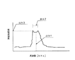
この(−)帯電型変調電磁波発生器3から発生する電流を、例えば400msサイクル(任意可変可能)で順次周波数を変えてコイル部2に流すと、図4に示す電磁波強度が得られる。なお、図4は周波数に対する電磁波強度のイメージ図であり、電磁波強度(出力3)で周波数帯(出力2)を有する主要周波数(出力1)を示す。また、出力3の電磁波強度はコイルに流す電流値に比例してその大きさが変化する。
When the current generated from the (−) charge-type modulated
P=K×i2×t
P:被処理水液体への変調電磁波照射エネルギー[W]
i:コイルに流れる電流[A]
t:照射時間[秒]
K:定数[H/m3]
P = K × i 2 × t
P: Modulated electromagnetic wave irradiation energy [W] to the water to be treated
i: Current flowing in the coil [A]
t: Irradiation time [seconds]
K: Constant [H / m 3 ]
次に、変調電磁波処理により金属セッケンの形成防止について説明する。
(−)帯電型変調電磁波処理水中で形成されるスケール結晶はその表面電位中性若しくは(−)マイナス帯電する事で、中継ポンプピット1および下水圧送管路7の内壁等の界面への電気的スケール付着を防止する。なお、前記界面とは、水と接するあらゆる境界面であり、水-スケール結晶、水-気泡(空気)、水-配管内壁等、水-油等が挙げられる。
Next, prevention of metal soap formation by modulated electromagnetic wave treatment will be described.
The scale crystal formed in the (−) charged modulated electromagnetic wave treated water is neutral to the surface potential or (−) negatively charged, so that the scale crystal is electrically connected to the interface such as the
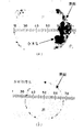
また、図5には中継ポンプピット1または下水圧送管路7の内壁とスケール結晶の電気的付着が(−)帯電型変調電磁波処理により電気的反発により無くなることを示す顕微鏡写真を示す。図5の顕微鏡写真は図6に示す後述の机上試験(ラボテスト)により行った結果を示すものである。
FIG. 5 shows a photomicrograph showing that the electrical adhesion between the inner wall of the
机上試験は次のような条件で行った。500mlのビーカに食品洗浄用の市販洗剤0.05g、市販サラダ油1.0g及び炭酸カルシウム粉末0.5gに東京都の上水500mlを加えて得られる水溶液に(−)帯電型変調電磁波処理をした処理水溶液と(−)帯電型変調電磁波処理をしない未処理水溶液を得た。これらの水溶液の一部をスポイドで採取して、ガラス板上に分取した。当該ガラス板を乾燥させて得られる油滴の界面付近の様子を顕微鏡で観察した。
前記(−)帯電型変調電磁波処理は、10Hz〜1MHzの時間と共に変化する周波数で、コイル電流値を0.75Aとして図6のガラスパイプに5回通液した。
The desktop test was conducted under the following conditions. A 500 ml beaker was subjected to (−) charged modulation electromagnetic wave treatment on an aqueous solution obtained by adding 500 ml of commercial water for washing food to 0.05 g of commercial detergent, 1.0 g of commercial salad oil, and 0.5 g of calcium carbonate powder. A treated aqueous solution and an untreated aqueous solution not subjected to (−) charged modulation electromagnetic wave treatment were obtained. A part of these aqueous solutions was collected with a spoid and collected on a glass plate. The state near the interface of the oil droplets obtained by drying the glass plate was observed with a microscope.
The (−) electrification type modulated electromagnetic wave treatment was conducted 5 times through the glass pipe of FIG. 6 with a coil current value of 0.75 A at a frequency varying with time of 10 Hz to 1 MHz.
図5(a)は(−)帯電型変調電磁波処理をしていない場合の水(外側)と油(内側)の界面におけるスケール結晶の顕微鏡写真であるが、硫化物固定剤として用いる金属塩の添加で油分と金属の結合により金属セッケンが形成され、この金属セッケンが油分内で水との界面付近に集合していることが分かる。しかし図5(b)に示すように(−)帯電型変調電磁波処理をすることで、油と金属イオンが共に(−)帯電型を帯びることにより、互いに反発して、水(外側)と油(内側)の界面における金属石けんの形成が抑えられる。 FIG. 5 (a) is a micrograph of a scale crystal at the interface between water (outside) and oil (inside) when (-) charged modulation electromagnetic wave treatment is not performed. It can be seen that a metal soap is formed by the combination of the oil and the metal by addition, and this metal soap is gathered near the interface with water in the oil. However, as shown in FIG. 5 (b), by performing the (-) charge-type modulated electromagnetic wave treatment, both the oil and the metal ions are (-) charged and repel each other, so that water (outside) and oil are repelled. Formation of metal soap at the (inner) interface is suppressed.
上記(−)帯電型変調電磁波処理によって金属セッケンの形成を抑えることで図1に示す中継ポンプピット1内でオイルボールが形成されることを防止し、さらに該金属石けんの集合体がピット1の内壁面へ付着することも抑制されるため、圧送管路7内に付着物が形成され難くなる。但し、金属セッケンの粘性物が多少は形成されるため、この粘性物が中継ポンプピット1と圧送管路7の壁面に粘着付着物を形成することは避けられない。
By suppressing the formation of metal soap by the above-mentioned (−) charged modulation electromagnetic wave treatment, oil balls are prevented from being formed in the
(2)硫化水素抑制剤の添加
上記(−)帯電型変調電磁波処理によって油分を含む金属セッケンの形成抑制効果だけでは避けられない粘性物の生成に起因して中継ポンプピット1の壁面と圧送管路7の内壁の粘着付着物は嫌気条件下において水中で溶解硫化水素を生成する。該硫化水素の発生を防止するために中継ポンプピット1において硫化水素抑制剤を添加することで粘着付着物から硫化水素が発生しないようにする。
(2) Addition of hydrogen sulfide inhibitor
Due to the formation of a viscous material that cannot be avoided only by the effect of suppressing the formation of metal soap containing oil by the above-described (−) electrification type modulated electromagnetic wave treatment, the adhesive deposits on the wall surface of the
硫化水素抑制剤としては、金属塩(亜鉛、ニッケル、アルミニウム、鉄、その他)を主体とする液体薬剤を中継ポンプピット1内に添加して硫化水素を硫化物として固定化を行うことで、前記硫化水素の発生を抑制する。硫化水素発生防止には、特に速効性に優れた抑制剤が望まれるが、前記金属塩の中で亜鉛又はニッケルが優れていることが分かった。
As a hydrogen sulfide inhibitor, by adding a liquid chemical mainly composed of a metal salt (zinc, nickel, aluminum, iron, etc.) into the
下水中の硫化水素は硫酸塩還元細菌の存在下で次のような反応で生成され、さらに硫黄酸化細菌により硫酸に成る。
SO4++2H2O+有機分 → 2HCO3-+H2S
硫酸塩還元細菌
H2S+2O2 → H2SO4
硫黄酸化細菌
Hydrogen sulfide in sewage is produced by the following reaction in the presence of sulfate-reducing bacteria, and further converted into sulfuric acid by sulfur-oxidizing bacteria.
SO 4+ + 2H 2 O + organic content → 2HCO 3 + + H 2 S
Sulfate-reducing bacteria
H 2 S + 2O 2 → H 2 SO 4
Sulfur-oxidizing bacteria
そこで、生成された硫化水素を金属塩により硫化物として次のように固定化する。 Zn2+ → ZnS
Ni2++S2- → NiS
Fe2++S2- → FeS
Therefore, the generated hydrogen sulfide is fixed as a sulfide with a metal salt as follows. Zn 2+ → ZnS
Ni 2+ + S 2- → NiS
Fe 2+ + S 2- → FeS
表1に前記Fe、Zn、NiおよびAgの硫化物の水に対する溶解度を示す。

生成した金属硫化物は水に対する溶解度が小さい程、下水中において金属硫化物を析出し、水中での硫化水素濃度は低下する。Ag金属塩は高価であるが、Zn又はNi金属塩は比較的安価であり、また、これらの金属塩を下水中に添加すると水に対する溶解度の小さい金属硫化物が得られることが分かる。現在下水の薬品処理において主として使用されているFe塩はZn又はNi塩と比較して水酸化物の形成性に違いがある。
下水は、ほぼpH6〜9の範囲のpH値を有するが、下水のpHに近いpH=4.5ではFe(三価)金属塩はFe水酸化物を形成するために水中のイオウイオンとの結合でFeSを生成するまでには至らない。また、Fe(二価)金属塩ではNi及びZn金属塩とほぼ同様に下水のpHに近いpH9〜10において水酸化物を形成するが、Ni及びZn金属硫化物形成能力においてNi・Zn金属塩に劣る事が判る。 Sewage has a pH value in the range of approximately pH 6-9, but at pH = 4.5, which is close to the pH of sewage, the Fe (trivalent) metal salt forms a Fe hydroxide with the sulfur ions in the water. This does not lead to the formation of FeS by bonding. Fe (divalent) metal salts form hydroxides at pH 9-10, which is close to the pH of sewage, in the same manner as Ni and Zn metal salts. It turns out that it is inferior to.
そこで図1に示すように、Ni又はZn系の薬品を薬品注入設備10から変調電磁波処理をしている中継ポンプピット1内に供給する。中継ポンプピット1内の処理後の硫化物含有量が薬品添加により減少した浄化下水はポンプ5で一旦マンホール6までくみ出され、その後自然流下される。
Therefore, as shown in FIG. 1, Ni or Zn-based chemicals are supplied from the
(3)硫化水素抑制剤の注入方法
次に硫化水素抑制剤の注入方法について述べる。
(a)注入率:下水流路内にて生成される下水中の硫化物濃度は1〜2ppm以上であるので、亜鉛成分又はニッケル成分を主体とする硫化物固定剤は、その金属濃度として硫化物濃度とほぼ同程度の濃度で添加すれば良い。
(3) Injection method of hydrogen sulfide inhibitor
Next, a method for injecting a hydrogen sulfide inhibitor will be described.
(A) Injection rate: Since the sulfide concentration in the sewage produced in the sewage flow path is 1 to 2 ppm or more, the sulfide fixing agent mainly composed of zinc component or nickel component is sulfided as its metal concentration. What is necessary is just to add with the density | concentration of about the same thing as a thing density | concentration.
(b)注入方法:
(b−1)間欠タイマー注入法
注入率は下水量により変動する。下水量が少ない場合は過剰注入となり、薬品コストが増加する。
(B) Injection method:
(B-1) Intermittent timer injection method
The injection rate varies depending on the amount of sewage. When the amount of sewage is small, over-injection will occur and chemical costs will increase.
(b−2)下水流量に対する定量注入法
下水流量データを基に時間帯流入水量に対する間欠タイマー注入方法を行う。本来中継ポンプピット1に流入する下水量に対して定量注入を実施するのが最適であるが、流入下水量を計測する測量計が高価である事と複数の流入経路もあり、圧送ポンプ5の吐出側の管路7に設けた流量計9の時間帯流量データを基に薬品注入量を間欠タイマー制御する。時間帯流量は平日と休日において大別される。
(B-2) Quantitative injection method for sewage flow rate
Based on the sewage flow rate data, the intermittent timer injection method for the inflow water amount in the time zone is performed. Originally, it is optimal to carry out a fixed amount injection for the amount of sewage flowing into the
(b−3)硫化水素濃度に対する補助注入法
前記(b−1)又は(b−2)の方式で硫化水素抑制剤を注入している際、マンホール6に設けた硫化水素濃度を測定する硫化水素計11の濃度が設定値を超えていることがモニタリングされた場合、設定するタイマー1回分だけ追加注入し、設定する時間内は、この追加注入を行わない。
(B-3) Auxiliary injection method for hydrogen sulfide concentration
When the hydrogen sulfide inhibitor is injected by the method (b-1) or (b-2), the concentration of the hydrogen sulfide meter 11 for measuring the hydrogen sulfide concentration provided in the
(4)下水流路の監視システム
先の変調電磁波処理及び硫化水素抑制剤の併用による下水処理システムでは、次のように下水流入量、中継ポンプ性能の確認、下水流路内の付着物量の把握及び薬品注入量など監視が必要である。本実施例の下水流路の監視システムは、既存のシステムにおける中継ポンプ5の吐出側の管路7に流量計9を取り付けるだけの簡単な工事で済む。本実施例では流量計9としてはドップラー式超音波流量計を用いた。
(4) Sewage channel monitoring system
In the sewage treatment system using the combined modulated electromagnetic wave treatment and hydrogen sulfide inhibitor, it is necessary to check the amount of sewage inflow, the relay pump performance, the amount of deposits in the sewage flow path, and the amount of chemical injection as follows. is there. The sewage flow path monitoring system of this embodiment can be simply constructed by simply attaching the
(a)流入水量の確認
下水圧送管路7に流入する下水量の把握と共に降雨量との相関値から下水管路に混入する不明水の混入量の予測が可能となる。不明水とは下水継ぎ手部等からの下水以外の混入する水の事である。なお中継ポンプピット1は容量が小さく、すぐ満タンになるので中継ポンプピット1への下水流入量と満タンに成った中継ポンプピット1から流出する量はほぼ同じとなり管路7の流量計9では中継ポンプピット1への流入水量が測定できる。
(A) Checking inflow water volume
As well as grasping the amount of sewage flowing into the
(b)中継ポンプ性能の確認
ポンプインぺラーの磨耗等の理由で中継ポンプ5の性能低下を生じるが、中継ポンプピット1に流入する流入水流量データを基に最大流入水量で下水が流入するときに、中継ポンプ5の吐出量が追いつかない場合には、マンホール6から外に下水が溢れることとなり、中継ポンプ5の性能の確認ができる。また、管路7に流入する流入下水の流量低下データが得られると、中継ポンプ5の能力劣化が予測されるので保守計画を作成する事が可能となる。
(B) Confirmation of relay pump performance
Although the performance of the relay pump 5 deteriorates due to wear of the pump impeller, etc., when the sewage flows in at a maximum inflow amount based on the inflow water flow rate data flowing into the
(c)下水流路付着物量の把握
ドップラー式超音波流量計9を用いる場合、圧送管路7の内壁に付着物が形成されて内径が小さくなればなる程、流速が増加する。そこで、圧送管路7の内壁に付着物が無い状態で計測した流速値と比較する事で監視データを基に圧送管路7の内壁への付着物増加の推定が可能である。また、(−)帯電型変調電磁波処理によって圧送管路7の内壁の付着物の抑制を行う当システムにおいてその処理効果を監視する事が可能である。
(C) Grasping the amount of sewage channel deposits
When the Doppler type
(d)薬品注入率の安定化
前記圧送管路7の流量データを基に薬品を安定した注入率で薬品注入設備10に注入でき、薬品注入割合の管理が可能となる。また、薬品の過剰注入を避ける事で薬品コストの削減が可能である。
(D) Stabilization of chemical injection rate
Based on the flow rate data of the
また、薬品注入設備10に超音波液位計(図示せず)を設けると、薬品使用量の確認、薬品の在庫確認が可能となり、また、薬品注入設備10から低水位信号が発せられると薬品補充管理を行う事が可能である。
In addition, if an ultrasonic liquid level meter (not shown) is provided in the
(5)机上試験
以上の変調電磁波処理及び硫化水素抑制剤の併用システムの机上試験について、次に述べる。
(a)(−)帯電型変調電磁波処理による金属セッケン形成の防止
試料として下水を用い、(−)帯電型変調電磁波処理装置により、10Hz〜20kHz間で変調した周波数、コイル電流値0.75Aで変調電磁波処理を行った。
(5) Desk test
The desktop test of the combined system of modulated electromagnetic wave treatment and hydrogen sulfide inhibitor will be described below.
(A) (-) Prevention of metal soap formation by charged electromagnetic wave treatment
Using sewage as a sample, modulated electromagnetic wave treatment was performed with a frequency modulated between 10 Hz and 20 kHz and a coil current value of 0.75 A using a (−) charged modulated electromagnetic wave treatment device.
机上試験として図6に示すガラスパイプに(−)帯電型変調電磁波発生器3に接続したコイル部2を巻き付けておき、これに10Hz〜20kHz間で変調した周波数、コイル電流値0.75Aで1回、3回、5回などの下水の通液テストを行い、通液をしていない未処理液と比較するテストを行った。
前記比較テストは試料をガラス板上に滴下し、乾燥させた後、得られた乾燥被膜の界面部の結晶状態を顕微鏡を用いて確認することで行った。
As a desktop test, the
The comparative test was performed by dropping a sample on a glass plate and drying it, and then confirming the crystal state of the interface portion of the obtained dried coating film using a microscope.
同様に、ガラスパイプに(+)帯電型変調電磁波発生器3(図示せず)に接続したコイル部2を巻き付けておき、これに(−)帯電型変調電磁波処理と同じ条件で電磁波処理を行った。
Similarly, a
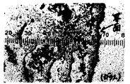
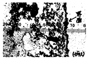
未処理の(変調電磁波処理をしない)場合の前記界面部の結晶状態の顕微鏡写真を図7に示し、(+)帯電型変調電磁波処理により5回通液テストした後の前記界面部の結晶状態の顕微鏡写真を図8に示す。
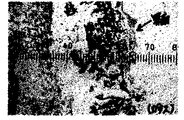
また、(−)帯電型変調電磁波処理により5回通液テストした後の前記界面部の結晶状態の顕微鏡写真を図9に示す。
FIG. 7 shows a photomicrograph of the crystal state of the interface when not treated (no modulation electromagnetic wave treatment), and (+) the crystal state of the interface after five liquid-flow tests by charge-type modulation electromagnetic wave treatment A micrograph of this is shown in FIG.
Moreover, the microscope picture of the crystal state of the said interface part after 5 liquid-flow tests by (-) electrification type | mold modulation electromagnetic wave process is shown in FIG.
図7の未処理の(変調電磁波処理をしない)場合には界面への有機分(金属セッケンを含む)及び結晶等の集合性が認められ、下水流路内へのスケールが付着し易いことが示されている。また、(+)帯電型変調電磁波処理をした場合には図8に示すように、前記未処理の場合に比較して界面への集合性物質の増加傾向があることが分かった。すなわち、下水に対して(+)帯電型変調電磁波処理を行うことは、逆効果であることが判明した。 In the case of untreated (without modulated electromagnetic wave treatment) in FIG. 7, organic substances (including metal soap) and crystals are collected at the interface, and the scale in the sewage flow path is likely to adhere. It is shown. In addition, as shown in FIG. 8, it was found that when the (+) charge-type modulated electromagnetic wave treatment was performed, there was a tendency for the aggregated material to increase at the interface as compared with the untreated case. That is, it has been found that performing (+) charged modulation electromagnetic wave treatment on sewage has an adverse effect.
これに対して、図9から(−)帯電型変調電磁波処理により、界面では集合性物質が形成される程度は減少しており、(−)帯電型変調電磁波処理が下水流路の内壁への付着物が生じることを抑制する作用があることが分かった。 On the other hand, from FIG. 9, the degree to which an aggregated material is formed at the interface is reduced by (−) charged modulated electromagnetic wave treatment, and (−) charged modulated electromagnetic wave treatment is applied to the inner wall of the sewage flow channel. It turned out that there exists an effect | action which suppresses that a deposit | attachment arises.
なお、図9に示す結果は5回(−)帯電型変調電磁波処理による通液テストした後の前記界面部の結晶状態の顕微鏡写真であるが、通液回数増加と共に界面に集合していた金属セッケン物質を含む結晶は徐々に減少傾向を示す。 In addition, although the result shown in FIG. 9 is a micrograph of the crystal state of the interface after 5 times of (-) charge-type modulated electromagnetic wave treatment, the metal gathered at the interface as the number of times of liquid passage increased. Crystals containing soap substances show a gradual decrease.
(b)硫化物抑制剤の選定−1
図1に示す圧送管路7において発生する硫化水素によるマンホール6のコンクリート壁面の腐食を防止するために、硫化物を金属塩により固定化し、圧送先における硫化水素ガスの発生を抑制するもっとも安価で、最適な硫化物抑制剤を選定する。
(B) Selection of sulfide inhibitor-1
In order to prevent corrosion of the concrete wall of the
試験方法は次の通りである。
まず試料としてpH6.5、導電率709μS/cmの滞留下水を用い、水で5倍希釈試料に調整し、その内の50ml(300ml密閉容器に分取)に次の薬剤を注入する。
The test method is as follows.
First, using sewage having a pH of 6.5 and conductivity of 709 μS / cm as a sample, the sample is adjusted to a 5-fold diluted sample with water, and the next drug is injected into 50 ml (sorted into a 300 ml sealed container).
A剤(有機系静菌剤)
B剤(Zn系金属塩:Zn含有率16%)
C剤(塩素系酸化剤)及び
D剤(過酸化水素:酸化剤)
次いで、10秒間の間、その容器を手で加温しながら10回振とうして混合する。得られ試料中の硫化水素の濃度をガス検知管法により測定した。
Agent A (Organic bacteriostatic agent)
Agent B (Zn-based metal salt: Zn content 16%)
C agent (chlorine oxidant) and
Agent D (hydrogen peroxide: oxidizing agent)
The mixture is then shaken 10 times for 10 seconds while warming the container by hand. The concentration of hydrogen sulfide in the obtained sample was measured by a gas detector tube method.
試験結果を表3示す。
表3の結果から次のことが判明した。
(a)Zn系金属塩を主体とする薬剤であるB剤(Zn系金属塩)が最も即効性に優れていた。B剤を5ppm注入した場合は、硫化水素は不検出であった。Zn成分の注入率としては0.8ppmが妥当である。
From the results in Table 3, the following was found.
(A) B agent (Zn-based metal salt), which is a drug mainly composed of Zn-based metal salt, was most excellent in immediate effect. When 5 ppm of B agent was injected, hydrogen sulfide was not detected. As an injection rate of the Zn component, 0.8 ppm is appropriate.
(b)C剤(酸化剤系薬剤)も若干の効果を示したが、注入率を増加させても硫化水素濃度の減少は見られなかった。 (B) C agent (oxidizing agent) also showed a slight effect, but no decrease in hydrogen sulfide concentration was observed even when the injection rate was increased.
(c)本机上試験は、未処理時の硫化水素濃度が16ppm程度と低かったので、実設備における100ppmを超える硫化水素濃度に対しては実機にて確認することが必要である。 (C) In this desk test, since the hydrogen sulfide concentration at the time of untreatment was as low as about 16 ppm, it is necessary to confirm the hydrogen sulfide concentration exceeding 100 ppm in the actual equipment with the actual machine.
(c)硫化物抑制剤の選定−2
前記硫化物抑制剤の選定試験−1で優れた効果を示した金属塩(Zn)以外の硫化物固定剤を選定する。その理由は下水道排出基準において「Zn5ppm以下である事」という制限があるために、前記試験のB剤(Zn系金属塩)の注入率5ppmでは該B剤はZn成分を0.8ppm含むものであるので、十分前記基準を満たしているが、下水排出基準より除外されている下記のNi系薬品、その他金属塩の選定を行った。
(C) Selection of sulfide inhibitor-2
A sulfide fixing agent other than the metal salt (Zn) that showed an excellent effect in the selection test-1 of the sulfide inhibitor is selected. The reason is that there is a restriction that “Zn is 5 ppm or less” in the sewage discharge standard, so that the B agent contains 0.8 ppm of the Zn component at an injection rate of 5 ppm of the B agent (Zn-based metal salt) in the above test. The following Ni chemicals and other metal salts that satisfy the above criteria but are excluded from the sewage discharge criteria were selected.
B剤(Zn系金属塩:Zn含有率16%)
E剤(Fe系金属塩:Fe含有率25%)及び
F剤(Ni系金属塩:Ni含有率15%)
また、更に高濃度の硫化水素を発生させる条件で上記効果を確認するために下水濃縮汚泥を試料として調整した。
Agent B (Zn-based metal salt: Zn content 16%)
E agent (Fe-based metal salt:
F agent (Ni-based metal salt: Ni content 15%)
Moreover, in order to confirm the said effect on the conditions which generate | occur | produce a further high concentration hydrogen sulfide, the sewage concentration sludge was adjusted as a sample.
試験方法は次の通りである。
まず、試料としてpH6.2、ORP(酸化還元電位)−280mVの下水濃縮汚泥を水で2倍に希釈した試料に調整し、200ml(500ml三角フラスコに分取)して硫化物抑制剤を注入する。フラスコを密栓して10秒間振とう・攪拌することを10回繰り返して十分混合する。得られた混合物を1分間静置した後、試料中の硫化水素の濃度をガス検知管法により測定した。
The test method is as follows.
First, adjust the pH 6.2, ORP (oxidation-reduction potential) -280 mV sewage-concentrated sludge to a sample diluted twice with water, and inject 200 ml (sorted into a 500-ml Erlenmeyer flask) with a sulfide inhibitor. To do. Seal the flask tightly and shake and agitate for 10
試験結果を表4に示す。
表4の結果から次のことが判明した。
(a)Zn系金属塩とNi系金属塩は、硫化物の固定化剤として優れている。特に、Zn系金属塩と比較してもNi系金属塩の方が優れている。
From the results in Table 4, the following was found.
(A) Zn-based metal salt and Ni-based metal salt are excellent as sulfide fixing agents. In particular, the Ni-based metal salt is superior to the Zn-based metal salt.
(b)Fe系は硫化水素の除去能力がほとんど認められなかった。
E剤(Fe含有率25%)を使用した場合には、金属濃度は高いにも関わらず、硫化水素固定による硫化水素除去率は低い。逆に、pH低下が増加している。これは試料液内で硫化水素の発生量が増加したためと考えられる。
(c)硫化水素固定剤としてはF剤(Ni系金属塩)が最も優れている。
(B) Fe-based hydrogen sulfide removal ability was hardly recognized.
When the E agent (Fe content: 25%) is used, the hydrogen sulfide removal rate by hydrogen sulfide fixation is low despite the high metal concentration. Conversely, the pH drop is increasing. This is probably because the amount of hydrogen sulfide generated in the sample solution increased.
(C) As a hydrogen sulfide fixing agent, F agent (Ni-based metal salt) is the most excellent.
(6)実設備試験
以上の検討の結果に基づき実設備を用いて次のような実設備での実証試験をおこなった。
(6) Actual equipment test
Based on the results of the above study, the following verification tests were conducted using actual equipment.
(a)処理条件
下水流入量780m3/日の中継ポンプピット1に投げ込みコイル式の(−)帯電型変調電磁波処理装置を用いて、コイル電流値3.5A、周波数10Hz〜20kHzの間を時間の経過ととも連続的に周波数(主要周波数は8000Hz近傍)を変調した。
(A) Processing conditions
Throw in sewage inflow 780m 3 / day into the
なお、使用薬品としてB剤(Zn系金属塩:Zn含有率16%:東洋クリーン化学(株)商品名シュカッターSW)を使用した。F剤(Ni系金属塩は市販品がないのでB剤(Zn系金属塩)を使用した。比較のためにE剤(Fe系金属塩:Fe含有率25%:工業薬品37%塩化第二鉄水溶液)も使用した。
In addition, B agent (Zn-type metal salt: Zn content rate 16%: Toyo Clean Chemical Co., Ltd. brand name cutter Cutter SW) was used as a chemical | medical agent used. Agent F (Ni-based metal salt is not commercially available, so agent B (Zn-based metal salt) was used. For comparison, agent E (Fe-based metal salt:
(b)試験結果−1
(−)帯電型変調電磁波処理により図1に示す中継ポンプピット1の内部に前記薬品を断続的に注入して発生する硫化水素濃度の経時変化を下水圧送先のマンホール6に設けた硫化水素濃度計11で測定した。結果を表5に示す。
(-) Hydrogen sulfide concentration provided in the
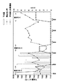
また、図10にはB剤(Zn系金属塩)とE剤(Fe系金属塩)を断続的に注入して、図1に示す中継ポンプピット1の内部で発生する硫化水素濃度の経時変化を下水圧送先のマンホール6に設けた硫化水素濃度計11で測定した結果を示す。
Also, FIG. 10 shows the time-dependent change in the concentration of hydrogen sulfide generated in the
なお、本実施例の電磁波処理を行わない場合に見られた中継ポンプピット1と圧送管路7の内壁に付着した付着物および下水中のオイルボールはかなりの程度減少していることを観察できた。
In addition, it can be observed that the deposits adhering to the inner wall of the
表5と図10の結果から次のことが分かった。
(c−1)Zn系金属塩
2〜5ppmの注入量で硫化水素発生は良好に抑制される。これは机上テストの結果と同様であった。Zn系金属塩を用いた場合は残留効果が得られ、5ppm以上の注入を1日継続した場合、約2〜3日迄圧送管路7の先の流路で硫化水素の発生が抑制された。
また、Zn系金属塩の注入を中止すると硫化水素濃度が高くなることが分かる。
From the results shown in Table 5 and FIG.
(C-1) Zn-based metal salt
Hydrogen sulfide generation is satisfactorily suppressed at an injection amount of 2 to 5 ppm. This was similar to the results of the desktop test. In the case of using a Zn-based metal salt, a residual effect was obtained. When injection of 5 ppm or more was continued for 1 day, generation of hydrogen sulfide was suppressed in the flow path ahead of the
It can also be seen that the concentration of hydrogen sulfide increases when the injection of the Zn-based metal salt is stopped.
(c−2)Fe系金属塩
硫化物固定化の能力はZn系金属塩と比較して著しく劣る。この結果も前記机上試験結果と同様であった。
(C-2) Fe metal salt
The ability to fix sulfides is significantly inferior to that of Zn-based metal salts. This result was also the same as the desktop test result.
なお、上記実施例では変調電磁波の周波数を10Hz〜20KHzとしているが、本発明の前記周波数は被処理の性状に応じて10Hz〜1MHzとすることができる。 In the above embodiment, the frequency of the modulated electromagnetic wave is 10 Hz to 20 KHz, but the frequency of the present invention can be 10 Hz to 1 MHz depending on the properties of the processing target.
本発明は、変調電磁波処理及び硫化水素抑制剤併用による滞留する下水流路内での壁面付着物の減少と硫化水素の生成を抑制する下水処理技術として、利用可能性が高い。 INDUSTRIAL APPLICABILITY The present invention has high applicability as a sewage treatment technique that suppresses the reduction of wall surface deposits and the generation of hydrogen sulfide in a staying sewage flow channel by using a combined electromagnetic wave treatment and a hydrogen sulfide inhibitor.
1 中継ポンプピット 2 コイル部
3 変調電磁波発生器 4 電磁波付与部
5 中継圧送ポンプ 6 マンホール
7 下水圧送管路 9 流量計
10 薬品注入設備 11 硫化水素濃度計
DESCRIPTION OF
Claims (8)
下水流路内を流れる下水に硫化水素抑制剤を供給する硫化水素抑制剤供給装置を備えたことを特徴とする下水流路の浄化装置。 Modulated electromagnetic wave provided with a coil part for electromagnetic wave treatment of sewage flowing in the sewage flow path, and a (−) charged modulation electromagnetic wave generator for supplying an alternating current whose frequency changes temporally in a band of 10 Hz to 1 MHz to the coil part. A processing device;
A purification apparatus for a sewage flow path, comprising a hydrogen sulfide inhibitor supply device for supplying a hydrogen sulfide inhibitor to sewage flowing in the sewage flow path.
Priority Applications (1)
| Application Number | Priority Date | Filing Date | Title |
|---|---|---|---|
| JP2004116626A JP3802907B2 (en) | 2004-04-12 | 2004-04-12 | Sewage flow purification method and apparatus |
Applications Claiming Priority (1)
| Application Number | Priority Date | Filing Date | Title |
|---|---|---|---|
| JP2004116626A JP3802907B2 (en) | 2004-04-12 | 2004-04-12 | Sewage flow purification method and apparatus |
Publications (2)
| Publication Number | Publication Date |
|---|---|
| JP2005296796A true JP2005296796A (en) | 2005-10-27 |
| JP3802907B2 JP3802907B2 (en) | 2006-08-02 |
Family
ID=35328990
Family Applications (1)
| Application Number | Title | Priority Date | Filing Date |
|---|---|---|---|
| JP2004116626A Expired - Fee Related JP3802907B2 (en) | 2004-04-12 | 2004-04-12 | Sewage flow purification method and apparatus |
Country Status (1)
| Country | Link |
|---|---|
| JP (1) | JP3802907B2 (en) |
Cited By (9)
| Publication number | Priority date | Publication date | Assignee | Title |
|---|---|---|---|---|
| WO2008129682A1 (en) * | 2007-04-10 | 2008-10-30 | Ska Ltd. | Method of testing prevention of metallic soap adhesion |
| WO2017038002A1 (en) * | 2015-09-03 | 2017-03-09 | メタウォーター株式会社 | Water discharge system |
| JP2018161640A (en) * | 2017-03-27 | 2018-10-18 | メタウォーター株式会社 | Water treatment equipment and water treatment method |
| JP2019013865A (en) * | 2017-07-04 | 2019-01-31 | 月島機械株式会社 | Sewage sludge treatment facility and sewage sludge treatment method |
| US10737956B1 (en) | 2019-12-12 | 2020-08-11 | Brian Rudy Parisien | Method and system for changing a property of a polar liquid |
| US10763021B1 (en) | 2019-10-31 | 2020-09-01 | Brian Rudy Parisien | Method of changing a property of a polar liquid |
| US10875794B1 (en) | 2019-10-31 | 2020-12-29 | Brian Rudy Parisien | Method of changing a property of a polar liquid |
| US10934186B1 (en) | 2019-12-12 | 2021-03-02 | Brian Rudy Parisien | Method and system for changing a property of a polar liquid |
| JP7527268B2 (en) | 2021-12-07 | 2024-08-02 | 株式会社クボタ | Missing Water Estimation System |
-
2004
- 2004-04-12 JP JP2004116626A patent/JP3802907B2/en not_active Expired - Fee Related
Cited By (12)
| Publication number | Priority date | Publication date | Assignee | Title |
|---|---|---|---|---|
| WO2008129682A1 (en) * | 2007-04-10 | 2008-10-30 | Ska Ltd. | Method of testing prevention of metallic soap adhesion |
| WO2017038002A1 (en) * | 2015-09-03 | 2017-03-09 | メタウォーター株式会社 | Water discharge system |
| JP2017047389A (en) * | 2015-09-03 | 2017-03-09 | メタウォーター株式会社 | Drainage system |
| JP2018161640A (en) * | 2017-03-27 | 2018-10-18 | メタウォーター株式会社 | Water treatment equipment and water treatment method |
| JP2019013865A (en) * | 2017-07-04 | 2019-01-31 | 月島機械株式会社 | Sewage sludge treatment facility and sewage sludge treatment method |
| US10763021B1 (en) | 2019-10-31 | 2020-09-01 | Brian Rudy Parisien | Method of changing a property of a polar liquid |
| US10875794B1 (en) | 2019-10-31 | 2020-12-29 | Brian Rudy Parisien | Method of changing a property of a polar liquid |
| EP3817011A1 (en) * | 2019-10-31 | 2021-05-05 | Brian Rudy Parisien | Method of changing a property of a polar liquid |
| EP3816115A1 (en) * | 2019-10-31 | 2021-05-05 | Brian Rudy Parisien | Method of changing a property of a polar liquid |
| US10737956B1 (en) | 2019-12-12 | 2020-08-11 | Brian Rudy Parisien | Method and system for changing a property of a polar liquid |
| US10934186B1 (en) | 2019-12-12 | 2021-03-02 | Brian Rudy Parisien | Method and system for changing a property of a polar liquid |
| JP7527268B2 (en) | 2021-12-07 | 2024-08-02 | 株式会社クボタ | Missing Water Estimation System |
Also Published As
| Publication number | Publication date |
|---|---|
| JP3802907B2 (en) | 2006-08-02 |
Similar Documents
| Publication | Publication Date | Title |
|---|---|---|
| Gabrielli et al. | Magnetic water treatment for scale prevention | |
| JP4305855B2 (en) | Apparatus and method for processing modulated electromagnetic field of fluid to be processed | |
| Gan et al. | Cathodic protection to mitigate external corrosion of underground steel pipe beneath disbonded coating | |
| JP3802907B2 (en) | Sewage flow purification method and apparatus | |
| SA92130158B1 (en) | A device for treating a liquid to prevent and/or remove scale | |
| JP6522293B2 (en) | Chemical cleaning method and chemical cleaning apparatus | |
| JP5337107B2 (en) | Apparatus and method for treating electromagnetic wave of fluid to be treated in water | |
| CN110841989A (en) | Gas-water pulse pipeline cleaning device with ozone cleaning and disinfecting functions | |
| CN104246016B (en) | The additive removed for heat exchanger deposit in wet preservation condition | |
| Bhatia | Cooling water problems and solutions | |
| JP3247942B2 (en) | Methods and equipment for rust prevention in fluid flow paths | |
| JP6114437B1 (en) | Corrosive anion removing apparatus and method for regenerating anion exchange resin | |
| JP4116002B2 (en) | Test method for water to be treated and method for preventing and / or removing rust, scale, and other components on the walls constituting the fluid flow path | |
| JP4538688B2 (en) | Method and apparatus for treating calcium-containing water | |
| Rao et al. | Ternary inhibitor system containing phosphonate, molybdate and Zn 2+ in corrosion control of carbon steel | |
| JP2000185290A (en) | Deodorizing method | |
| JP2007222749A (en) | Waste water treatment apparatus and method | |
| McClanahan et al. | Effect of pH on quality of calcium carbonate film deposited from moderately hard and hard water | |
| JP2010110667A (en) | Electromagnetic treatment apparatus and method | |
| Nguyen | Interactions between copper and chlorine disinfectants: chlorine decay, chloramine decay and copper pitting | |
| DeBerry | Corrosion in potable water systems | |
| CN213295073U (en) | Device for treating circulating water by using alternating electromagnetic field and chemical agent | |
| JP3512108B2 (en) | Cooling water treatment method and treatment device | |
| JP2001259691A (en) | Method and device for preventing deposition of rust, scale and other component in fluid passage and/or removing the deposit | |
| Alshehri | Impact of corrosion inhibitor blended orthophosphate on water quality in water distribution systems |
Legal Events
| Date | Code | Title | Description |
|---|---|---|---|
| A977 | Report on retrieval |
Free format text: JAPANESE INTERMEDIATE CODE: A971007 Effective date: 20060113 |
|
| A131 | Notification of reasons for refusal |
Free format text: JAPANESE INTERMEDIATE CODE: A131 Effective date: 20060131 |
|
| A521 | Written amendment |
Free format text: JAPANESE INTERMEDIATE CODE: A523 Effective date: 20060329 |
|
| TRDD | Decision of grant or rejection written | ||
| A01 | Written decision to grant a patent or to grant a registration (utility model) |
Free format text: JAPANESE INTERMEDIATE CODE: A01 Effective date: 20060425 |
|
| A61 | First payment of annual fees (during grant procedure) |
Free format text: JAPANESE INTERMEDIATE CODE: A61 Effective date: 20060428 |
|
| R150 | Certificate of patent (=grant) or registration of utility model |
Free format text: JAPANESE INTERMEDIATE CODE: R150 |
|
| FPAY | Renewal fee payment (prs date is renewal date of database) |
Free format text: PAYMENT UNTIL: 20100512 Year of fee payment: 4 |
|
| FPAY | Renewal fee payment (prs date is renewal date of database) |
Free format text: PAYMENT UNTIL: 20110512 Year of fee payment: 5 |
|
| FPAY | Renewal fee payment (prs date is renewal date of database) |
Free format text: PAYMENT UNTIL: 20120512 Year of fee payment: 6 |
|
| FPAY | Renewal fee payment (prs date is renewal date of database) |
Free format text: PAYMENT UNTIL: 20130512 Year of fee payment: 7 |
|
| FPAY | Renewal fee payment (prs date is renewal date of database) |
Free format text: PAYMENT UNTIL: 20130512 Year of fee payment: 7 |
|
| R250 | Receipt of annual fees |
Free format text: JAPANESE INTERMEDIATE CODE: R250 |
|
| LAPS | Cancellation because of no payment of annual fees |