JP2005296781A - Pump dispenser - Google Patents
Pump dispenser Download PDFInfo
- Publication number
- JP2005296781A JP2005296781A JP2004115908A JP2004115908A JP2005296781A JP 2005296781 A JP2005296781 A JP 2005296781A JP 2004115908 A JP2004115908 A JP 2004115908A JP 2004115908 A JP2004115908 A JP 2004115908A JP 2005296781 A JP2005296781 A JP 2005296781A
- Authority
- JP
- Japan
- Prior art keywords
- pump dispenser
- nozzle head
- head
- nozzle
- dispenser according
- Prior art date
- Legal status (The legal status is an assumption and is not a legal conclusion. Google has not performed a legal analysis and makes no representation as to the accuracy of the status listed.)
- Pending
Links
- 239000007788 liquid Substances 0.000 claims abstract description 14
- 238000013461 design Methods 0.000 abstract description 11
- 239000002184 metal Substances 0.000 abstract description 4
- 238000004519 manufacturing process Methods 0.000 abstract description 3
- 230000000007 visual effect Effects 0.000 abstract description 3
- 239000002453 shampoo Substances 0.000 description 8
- 238000012986 modification Methods 0.000 description 4
- 230000004048 modification Effects 0.000 description 4
- 238000003780 insertion Methods 0.000 description 3
- 230000037431 insertion Effects 0.000 description 3
- 238000005516 engineering process Methods 0.000 description 2
- 238000001746 injection moulding Methods 0.000 description 2
- 239000006210 lotion Substances 0.000 description 2
- 238000000034 method Methods 0.000 description 2
- 238000000465 moulding Methods 0.000 description 2
- 238000012805 post-processing Methods 0.000 description 2
- 239000007921 spray Substances 0.000 description 2
- 229920003002 synthetic resin Polymers 0.000 description 2
- 239000000057 synthetic resin Substances 0.000 description 2
- 238000005452 bending Methods 0.000 description 1
- 239000000919 ceramic Substances 0.000 description 1
- 238000007599 discharging Methods 0.000 description 1
- 238000011160 research Methods 0.000 description 1
- 238000007711 solidification Methods 0.000 description 1
- 230000008023 solidification Effects 0.000 description 1
- 238000005507 spraying Methods 0.000 description 1
Images


Landscapes
- Closures For Containers (AREA)
Abstract
Description
本発明は、シャンプー等の粘性の高い液体の吐出、或いは化粧水等の粘性の低い液体の吐出・噴霧を手動操作により行うポンプディスペンサーに関する。
特に、ノズルヘッドの外観形状の設計変更を容易に行うことができるポンプディスペンサーに関する。
The present invention relates to a pump dispenser that manually discharges a highly viscous liquid such as a shampoo or discharges / sprays a low viscosity liquid such as a lotion.
In particular, the present invention relates to a pump dispenser that can easily change the design of the external shape of a nozzle head.
従来、ノズルヘッドを上下移動させることで容器内の液体を外部に吐出することができるポンプディスペンサーとして、図8及び図9に示すポンプディスペンサーが知られている(例えば、特許文献1参照)。
ここで、図8は、従来のポンプディスペンサーの全体構成を示しており、図9は、ノズルヘッド付近の外観を示している。
Conventionally, a pump dispenser shown in FIGS. 8 and 9 is known as a pump dispenser capable of discharging the liquid in the container to the outside by moving the nozzle head up and down (see, for example, Patent Document 1).
Here, FIG. 8 shows the overall configuration of a conventional pump dispenser, and FIG. 9 shows the appearance near the nozzle head.
このポンプディスペンサーには、バージンシールSによって未使用状態に保持されている。
図8において、101は液体Lの入った容器、102は容器101の口部に取り付けられたキャップ、103はこのキャップ102に対してピストンと同時に上下移動可能に装着されたノズルヘッドである。
そしてノズルヘッド103を上下移動させることで、容器101内の液体Lを外部に吐出することができる。
This pump dispenser is held unused by a virgin seal S.
In FIG. 8, 101 is a container containing liquid L, 102 is a cap attached to the mouth of the
By moving the
図8においてまた、104はキャップ102の内側に結合して容器101内に垂下されたチューブ、105はノズルヘッド103の下部に一体結合しノズルヘッド103とともに上下移動するピストン、106はピストン105を上方付勢するスプリング、107はピストン105内に装着されたバルブ、108はチューブ104内に装着されたバルブである。
In FIG. 8, 104 is a tube that is coupled to the inside of the
キャップ102にはピストン嵌挿用孔102aが形成されており、このピストン嵌挿用孔102aの奥部には、下垂するリング部109が一体形成されている。
チューブ104は、その上部嵌合部104aでリング部109に嵌合する。
また、ピストン105は、リング部内に接して上下移動するようになっている。
The
The
The
ノズルヘッド103の下方移動を阻止するためのバージンシールSはキャップ102に切り離し可能な状態で一体化して設けられている。
図8及び図9に示すようにバージンシールSは、好ましくは円筒状に形成され、ピストン嵌挿用孔102aに沿った薄肉部110Aを介してキャップ102と結合している。
そのためポンプディスペンサーを使用する際には、このバージンシールSをキャップ102の縦スリット111から全周を切り離して使用する。
A virgin seal S for preventing the
As shown in FIGS. 8 and 9, the virgin seal S is preferably formed in a cylindrical shape, and is coupled to the
Therefore, when using the pump dispenser, the virgin seal S is used by separating the entire circumference from the
しかしながら、上述したようなポンプディスペンサーでは、例えば、シャンプーとリンスとでその外観を変え、そのバリエーションとして、ノズルヘッドの形状を例えばハート形状とスペード形状との組み合わせにしたい場合に、ノズルヘッド成形用の金型をバリエーションの数だけ作製しなければならない。
これでは、手間がかかる上コストアップとなる。
However, in the pump dispenser as described above, for example, when the appearance is changed between shampoo and rinse, and as a variation, the shape of the nozzle head is, for example, a combination of a heart shape and a spade shape, the nozzle head molding is used. The mold must be made in the number of variations.
This takes time and increases the cost.
本発明は、かかる背景技術をもとになされたもので、上記の背景技術の問題点を克服するためになされたものである。
すなわち、本発明は、ノズルヘッドの形状を手軽に且つさほどのコストを要せずに変更することができるポンプディスペンサーを提供することを目的とする。
The present invention has been made on the basis of such background technology, and has been made to overcome the above-described problems of the background technology.
That is, an object of the present invention is to provide a pump dispenser capable of easily changing the shape of the nozzle head without requiring much cost.
かくして、本発明者は、このような課題背景に対して鋭意研究を重ねた結果、ノズルヘッドの視認し易い位置に別部材であるヘッドプレートを取り付け、このヘッドプレートに幾つかのバリエーションを設けることで、ノズルヘッドの形状の変更が可能となることを見出し、この知見に基づいて本発明を完成させたものである。 Thus, as a result of earnest research on the background of such problems, the present inventor attaches a head plate which is a separate member to a position where the nozzle head is easily visible, and provides several variations on the head plate. Thus, it has been found that the shape of the nozzle head can be changed, and the present invention has been completed based on this finding.
すなわち、本発明は、(1)、容器の口部に取り付けられたキャップ部に対して上下移動可能に設けられるノズルヘッドから、容器内の液体を吐出するように構成されたポンプディスペンサーであって、前記ノズルヘッドには、該ノズルヘッドを覆う薄板状のヘッドプレートが別体として設けられているポンプディスペンサーに存する。 That is, the present invention is (1) a pump dispenser configured to discharge a liquid in a container from a nozzle head provided so as to be movable up and down with respect to a cap part attached to the mouth of the container. The nozzle head is a pump dispenser in which a thin plate-like head plate that covers the nozzle head is provided separately.
すなわち、本発明は、(2)、前記ヘッドプレートはノズルヘッドに取外し自在に設けられているポンプディスペンサーに存する。 That is, the present invention resides in (2) a pump dispenser in which the head plate is detachably provided on the nozzle head.
すなわち、本発明は、(3)、 前記ノズルヘッドには該ノズルヘッドを上方向に付勢するための板バネが一体成形されている上記(1)に記載のポンプディスペンサーに存する。 That is, the present invention resides in (3) the pump dispenser according to (1), wherein a plate spring for urging the nozzle head upward is integrally formed with the nozzle head.
すなわち、本発明は、(4)前記板バネの一端は、キャップ部の溝穴に係止されている上記(3)に記載のポンプディスペンサーに存する。 That is, the present invention resides in (4) the pump dispenser according to the above (3), wherein one end of the leaf spring is locked in the slot of the cap portion.
すなわち、本発明は、(5)、前記ノズルヘッドには、該ノズルヘッドから延出するノズル先端部が別体として設けられている上記(1)に記載のポンプディスペンサーに存する。 That is, the present invention resides in (5) the pump dispenser according to (1), wherein the nozzle head is provided with a nozzle tip portion extending from the nozzle head as a separate body.
すなわち、本発明は、(6)、前記ノズル先端部に被せるための蓋体をノズル先端部に開閉可能に一体に設けた上記(5)に記載のポンプディスペンサーに存する。 That is, the present invention resides in (6) the pump dispenser according to (5), wherein a lid for covering the nozzle tip is integrally provided at the nozzle tip so as to be openable and closable.
すなわち、本発明は、(7)、前記ノズル先端部の突起部にヘッドプレートの溝部が嵌まり込むことで回り止め機能を有している上記(5)に記載のポンプディスペンサーに存する。 That is, the present invention resides in (7) the pump dispenser according to (5), wherein the groove portion of the head plate is fitted into the protrusion at the tip of the nozzle and has a function of preventing rotation.
すなわち、本発明は、(8)、前記ノズル先端部の傾斜角度θは30°以上である上記(5)に記載のポンプディスペンサーに存する。 That is, the present invention resides in (8) the pump dispenser described in (5) above, wherein the inclination angle θ of the nozzle tip is 30 ° or more.
すなわち、本発明は、(9)、キャップ部にはシリンダー部とそれに通じるチューブ部が一体形成され、且つシリンダー部にはバージンシールが一体形成されている上記(1)に記載のポンプディスペンサーに存する。 That is, the present invention resides in (9) the pump dispenser according to (1), wherein the cap portion is integrally formed with a cylinder portion and a tube portion communicating therewith, and the cylinder portion is integrally formed with a virgin seal. .
すなわち、本発明は、(10)、バージンシールは、キャップ部の前方に切り離し可能に一体形成されている上記(9)に記載のポンプディスペンサーに存する。 That is, the present invention resides in (10), the pump dispenser according to (9), wherein the virgin seal is integrally formed so as to be detachable in front of the cap portion.
なお、本発明の目的に添ったものであれば、上記(1)から(10)を適宜組み合わせた構成も採用可能である。 In addition, as long as the objective of this invention is met, the structure which combined said (1) to (10) suitably is also employable.
本発明のポンプディスペンサーには、該ノズルヘッドを覆う薄板状のヘッドプレートが別体として設けられているため、ノズルヘッドのデザインの変更をしたい場合に、外観上顕著に視認される位置にあるヘッドプレートを取り替えることで達成できる。 In the pump dispenser of the present invention, a thin plate-like head plate that covers the nozzle head is provided as a separate body. Therefore, when it is desired to change the design of the nozzle head, the head is in a position that can be visually recognized visually. This can be achieved by replacing the plate.
ノズルヘッド全体の設計変更を行わなくても、同様な視覚的効果が得られる。
ノズルヘッド全体を設計変更する場合には、比較的複雑な構造の金型を作製し直さなければならないが、ヘッドプレートのみの変更であれば、簡易な構造の安価な金型を作製するだけで済み、金型作製に関して省力化や低コスト化を図ることができる。
The same visual effect can be obtained without changing the design of the entire nozzle head.
When changing the design of the entire nozzle head, it is necessary to recreate a mold with a relatively complicated structure. However, if only the head plate is changed, it is only necessary to produce an inexpensive mold with a simple structure. In addition, labor saving and cost reduction can be achieved for mold fabrication.
そしてこのように簡易にヘッドプレートを取り替えできるので、ノズルヘッド付近の外観形状を例えば、シャンプー、リンス、及びボディーシャンプーといった種別毎に特有のものに容易に変更することも容易にできる。
またノズルヘッド21を上方に付勢するための板バネ22は、ノズルヘッド21と一体成形されていることで、両者間での滑りやガタ付きがない。
Since the head plate can be easily replaced in this way, the appearance shape near the nozzle head can be easily changed to a unique one for each type, for example, shampoo, rinse, and body shampoo.
Further, the
キャップ部11、チューブ部12、バージンシール13、及びシリンダー部14が一体成形されているため、部品点数の大幅な削減が図られ、組み付けも容易となる。
また、各部品同士の滑りや、がたつきがないためにポンプディスペンサーPの動きが安定したものとなる。
Since the
In addition, the movement of the pump dispenser P is stable because there is no slippage or rattling between the components.
以下、本発明を実施するための最良の形態を図面に基づいて説明する。
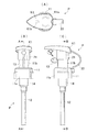
図1は、本発明の一実施形態に係るポンプディスペンサーを示している。
図1(A)は平面図、図1(B)は正面図、及び図1(C)は側面図を示す。
Hereinafter, the best mode for carrying out the present invention will be described with reference to the drawings.
FIG. 1 shows a pump dispenser according to an embodiment of the present invention.
1A is a plan view, FIG. 1B is a front view, and FIG. 1C is a side view.
この一実施形態のポンプディスペンサーPは、容器の口部に螺合して取り付けられるキャップ部11と、ノズルヘッド21を備えており、このキャップ部11には一体成形されたシリンダー部14と該シリンダー部14に一体化されたチューブ部12とを備える。
シリンダー部14内にはまたピストン部15が上下に往復移動自在に配設される。
ピストン部15はシリンダー部14内の液体(すなわちピストン部15とFバルブとの間の空間Sの液体)を押圧してノズル先端部Nから吐出させる。
なお、ノズル先端部Nのある側を前方とする。
キャップ部11は、下方に突出する大径部11aと、この大径部11aと同心軸上で連結され上方及び下方に突出する小径部11bとから形成されている。
The pump dispenser P according to this embodiment includes a
A
The
The side with the nozzle tip N is defined as the front.
The
この小径部11bは、その上端がノズルヘッド21と係合することで取り付けられる。
また大径部11aは、キャップ部11の握り部となる。
このノズルヘッド21の直下には、キャップ部11(詳しくは小径部11b)の前方に一体成形されたバージンシール13が切り離し可能なように設けられている。
バージンシール13は、キャップ部11の上面とノズルヘッド21の下端部との間に介在してノズルヘッド21の下方への移動を阻止している。
The
The
A
The
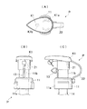
ここでバージンシール13の具体的な形状を図2に示す。
図2(A)に示すようにバージンシール13は、三角形状の摘み部13aとこの摘み部13aと連結された棒状体部13bとを有している。
Here, a specific shape of the
As shown in FIG. 2A, the
摘み部13aの両側には浅い三角形の凹みが形成されており、A−A線に沿った断面を示すと、図2(B)のようになる。
棒状体部13bは、図2(C)の横断面で分かるように、薄肉部を介してキャップ部11(詳しくは、小径部11b)に連結されている。
そのため、摘み部13aを両側から摘んで強く引っ張れば、摘み部13aはこの棒状体部13bの薄肉部のところから切り離される。
この時、指で両側の三角形の凹みを強く把持することができ、滑りにくくて便利である。
Shallow triangular depressions are formed on both sides of the
The rod-shaped
Therefore, if the knob | pick
At this time, it is possible to hold the triangular dents on both sides strongly with a finger, and it is difficult to slide and is convenient.
一方、ノズルヘッド21の上方には、一定形状(ここではハート形状)をしたヘッドプレートK1が、ノズルヘッド21を覆うように取り付けられている。
このヘッドプレートK1は別体としてノズルヘッド21に取外し可能に設けられているので、取り替えることができる自由度がある。
On the other hand, a head plate K <b> 1 having a fixed shape (here, a heart shape) is attached above the
Since this head plate K1 is detachably provided on the
このヘッドプレートK1のノズルヘッド21への取付けは、具体的には、ヘッドプレートK1の裏面(下面)に形成された2筋の突起K1aをノズルヘッド21に形成された切欠部に嵌入させることで行う。
そして当時にヘッドプレートK1の裏面に形成された溝部K1bにノズル先端部Nに形成された突起部Naを挿入させる。
なお、この突起部NaはヘッドプレートK1の回り止め機能をもつ。
すなわちヘッドプレートK1は上記のように3箇所で他の部材(ノズルヘッド21やノズル先端部N)と係合され、安定した状態で所定の位置に配置されることとなる(図1(A)参照)。
Specifically, the head plate K1 is attached to the
Then, the protrusion Na formed on the nozzle tip N is inserted into the groove K1b formed on the back surface of the head plate K1 at that time.
The protrusion Na has a function of preventing the head plate K1 from rotating.
That is, the head plate K1 is engaged with the other members (the
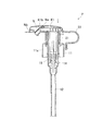
次に、図3に示すポンプディスペンサーPの断面図を用いて、その内部構造等について更に説明する。
図3(A)は図1(C)のB−B線に沿う断面図であり、図3(B)は図1(B)のA−A線に沿う断面図である。
図に示すように、キャップ部11、チューブ部12、バージンシール13、及びシリンダー部14は一体成形されており、部品点数の大幅な削減が図られているため、組み付けが極めて容易である。
また、各部品同士の滑りやガタ付きが生じないためにポンプディスペンサーPの動きが安定したものとなる。
Next, the internal structure of the pump dispenser P shown in FIG. 3 will be further described.
3A is a cross-sectional view taken along the line BB in FIG. 1C, and FIG. 3B is a cross-sectional view taken along the line AA in FIG.
As shown in the figure, the
Further, since the sliding and backlash between the parts do not occur, the movement of the pump dispenser P becomes stable.
薄板状のヘッドプレートK1は、前述したように、ノズルヘッド21を覆うように取り付けられているために、外観上、視認識し易い位置にある。
そのためノズルヘッド21のデザインの変更を行いたい場合には、ヘッドプレートK1を設計変更してノズルヘッド21を取り付ければ足り、ノズルヘッド全体の設計変更と同等の視覚的効果が得られる利点がある。
因みに、ノズルヘッド全体を設計変更する場合には、比較的複雑な構造の金型を作製し直さなければならないが、ヘッドプレートK1のみの変更であれば、簡易な構造の安価な金型を作製するだけで済み、金型作製に関して省力化や低コスト化を図ることができる。
そして、このように簡易にヘッドプレートK1を作製できるので、ノズルヘッド本体の部分は汎用的に同じものが使える上に、ノズルヘッド付近の外観形状を例えば、シャンプー、リンス、及びボディーシャンプーといった種別毎に変更することも容易に可能である。
Since the thin plate-like head plate K1 is attached so as to cover the
Therefore, when it is desired to change the design of the
Incidentally, when changing the design of the entire nozzle head, it is necessary to remanufacture a mold having a relatively complicated structure. However, if only the head plate K1 is changed, an inexpensive mold having a simple structure is manufactured. All that is required is labor saving and cost reduction for mold fabrication.
Since the head plate K1 can be easily produced in this way, the same part can be used for the nozzle head body in general, and the external shape in the vicinity of the nozzle head can be changed for each type such as shampoo, rinse, and body shampoo. It is also possible to easily change to
ノズルヘッド21には、該ノズルヘッド21から延出するノズル先端部Nが別体として設けられている。
このようにノズルヘッド21とノズル先端部Nとを別体とすることで、ポンプディスペンサーPにおいてノズル先端部Nの傾斜角度θ(いわゆる水平方向に対する角度)を従来より大きくすることができる。
図では、ノズル先端部Nは45度下方へ傾斜している場合を示したが、このようにノズル口を極力下側へ向けるようにすることで、シャンプーやリンス等を頭上から、直接、頭部に吹き付ける際に、より容易に下方へ吐出できる。
The
Thus, by making the
In the figure, the case where the nozzle tip N is inclined downward by 45 degrees is shown. However, by directing the nozzle mouth downward as much as possible, the shampoo, rinse, etc. can be directly applied to the head from the overhead. When spraying on the part, it can be discharged more easily downward.
因みに、従来は、ノズルヘッド21と一体成形されていたので、金型の構造設計上(すなわち、金型離型時の抵抗や、アンダーカットの配置)、ノズルの傾斜角度は30度が限界とされていた。
因みに、ノズルヘッドのノズル先端部の形状を成形後、後処理によってストレート形状から曲げ形状に屈曲させる方法もあったが強度の低下や工数が増える等の問題があった。
Incidentally, since the
Incidentally, there is a method in which the shape of the nozzle tip of the nozzle head is molded and then bent from a straight shape to a bent shape by post-processing, but there are problems such as a decrease in strength and an increase in man-hours.
しかしながら、ノズル先端部Nをノズルヘッド21と別体としたことでかかる問題は解消される。
ノズルヘッド21と一体成形された板バネ22の一端は、キャップ部11の溝穴H(外周に二重壁で形成されている)に係止されている。
板バネ22の一端は係止突起を有しており、この係止突起をキャップ部11の溝穴に挿入することでワンタッチで組み付けられる利点がある。
板バネ22は、ノズルヘッド21を押し込まない状態においても上方へ付勢されており弾発力を有する。
However, this problem is solved by making the nozzle tip N separate from the
One end of a
One end of the
The
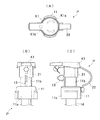
いま、バージンシール13を剥がし、ノズル先端部Nにヒンジ結合されノズル先端部Nのノズル口を覆う蓋体Nbを開状態にしてから、ノズルヘッド21をキャップ部11に対して下降させると、図4に示すように、板バネ22が大きく撓む。
具体的には、ノズルヘッド21を手の平で押し込んで行くと、板バネ22は曲率半径が小さくなるように急カーブに撓み、弾性エネルギーが更に蓄えられ、弾発力を増して行く。
Now, when the
Specifically, when the
そのため、ノズルヘッド21から手を離すと、板バネ22に蓄えられた弾発力により、速やかにノズルヘッド21が上昇して元の位置に戻る。
板バネ22は、ノズルヘッド21と一体成形されているため(例えば、合成樹脂で射出成形により一体化されている)、両者間での滑りやガタ付きがなく、撓みによる板バネ22のエネルギーが効率良くノズルヘッド21に伝わる。
Therefore, when the hand is released from the
Since the
なお、ノズル先端部Nに一体的にヒンジ結合された蓋体Nbを設けたことで、使用後はすぐにノズル先端部Nに蓋をすることができ、漏れだした液体が空気との接触により固化するようなことはない。
また一体的にヒンジ結合された蓋体Nbを設けたことで、蓋体Nbが紛失するようなことも防げる。
In addition, by providing the cover body Nb integrally hinged to the nozzle tip N, the nozzle tip N can be covered immediately after use, and the leaked liquid is brought into contact with the air. There is no solidification.
Further, by providing the cover body Nb integrally hinged, it is possible to prevent the cover body Nb from being lost.
以上、本発明を説明してきたが、本発明は上述した一実施形態にのみ限定されるものではなく、その本質を逸脱しない範囲で、他の種々の変形が可能であることはいうまでもない。
例えば、上述した一実施形態では、ヘッドプレートK1の形状としてハート形の例を示したが、他の形状であっても良い。
以下、他の形状の例を3パターン、図5〜図7を用いて説明する。
Although the present invention has been described above, the present invention is not limited to the above-described embodiment, and various other modifications can be made without departing from the essence thereof. .
For example, in the above-described embodiment, an example of a heart shape is shown as the shape of the head plate K1, but other shapes may be used.
Hereinafter, examples of other shapes will be described with reference to three patterns, FIGS.
図5に示すヘッドプレートK2は、図1に示したヘッドプレートK1と比べて、ハート形から雫形に変更されている点で大きく異なる。
かかる形状の変更は、ハート形用の金型に後加工を施すことによって、行うことができ、更なる省資源化、低コスト化を図ることができる。
The head plate K2 shown in FIG. 5 is greatly different from the head plate K1 shown in FIG. 1 in that it is changed from a heart shape to a bowl shape.
Such a shape change can be performed by post-processing the heart-shaped mold, and further resource saving and cost reduction can be achieved.
図6に示すヘッドプレートK3は、図1に示したヘッドプレートK1と比べて、ハート形から前方後円形状に変更されている点で大きく異なる。
この形状では、ヘッドプレートK1,K2と同様に長方形状の部分が目印となりノズル吐出側を容易に把握することができる。
The head plate K3 shown in FIG. 6 is greatly different from the head plate K1 shown in FIG. 1 in that it is changed from a heart shape to a front rear circular shape.
In this shape, a rectangular portion becomes a mark as with the head plates K1 and K2, and the nozzle discharge side can be easily grasped.
図7に示すヘッドプレートK4は、図6に示したヘッドプレートK3と比べて、角張った前方後円形状のヘッドプレートK3に変更されている点で異なる。
この形状でも、長方形状の部分が目印となりノズル吐出側を容易に把握することができる。
一方、ポンプディスペンサーは、キャップ部11、チューブ部12、バージンシール13、及びシリンダー部14は、合成樹脂により射出成形等により一体化されているが、一部を他の部材(金属又はセラミック)としてインサート成形することも可能である。
The head plate K4 shown in FIG. 7 is different from the head plate K3 shown in FIG. 6 in that the head plate K4 is changed to an angular front rear circular head plate K3.
Even in this shape, the rectangular portion serves as a mark, and the nozzle discharge side can be easily grasped.
On the other hand, in the pump dispenser, the
本発明は、シャンプー等の粘性の高い液体の吐出、或いは化粧水等の粘性の低い液体の吐出・噴霧を手動操作により行うポンプディスペンサーに関するものであるが、その原理を用いる限り、他の噴射用の容器の分野にも適用可能であり、その応用分野は広範囲のもきである。 The present invention relates to a pump dispenser that manually discharges a highly viscous liquid such as a shampoo or discharges / sprays a low viscosity liquid such as a lotion. It can be applied to the field of containers, and its application field is wide-ranging.
11 キャップ部
11a 大径部
11b 小径部
12 チューブ部
13 バージンシール
13a 摘み部
13b 棒状体部
14 シリンダー部
15 ピストン部
21 ノズルヘッド
22 板バネ
101 容器
102 キャップ
102a ピストン嵌挿用孔
103 ノズルヘッド
104 チューブ
104a 上部嵌合部
105 ピストン
106 スプリング
107,108 バルブ
109 リング部
110A 薄肉部
111 縦スリット
H 溝穴
K1,K2,K3,K4 ヘッドプレート
K1a 突起
K1b 溝部
L 液体
N ノズル先端部
Na 突起部
Nb 蓋体
P ポンプディスペンサー
T 空間
S バージンシール
11
14
Claims (10)
前記ノズルヘッドには、該ノズルヘッドを覆う薄板状のヘッドプレートが別体として設けられていることを特徴とするポンプディスペンサー。 A pump dispenser configured to discharge the liquid in the container from a nozzle head provided to be movable up and down with respect to the cap part attached to the mouth of the container,
A pump dispenser, wherein the nozzle head is provided with a thin plate-like head plate that covers the nozzle head as a separate body.
The pump dispenser according to claim 9, wherein the virgin seal is integrally formed so as to be detachable in front of the cap portion.
Priority Applications (1)
| Application Number | Priority Date | Filing Date | Title |
|---|---|---|---|
| JP2004115908A JP2005296781A (en) | 2004-04-09 | 2004-04-09 | Pump dispenser |
Applications Claiming Priority (1)
| Application Number | Priority Date | Filing Date | Title |
|---|---|---|---|
| JP2004115908A JP2005296781A (en) | 2004-04-09 | 2004-04-09 | Pump dispenser |
Publications (1)
| Publication Number | Publication Date |
|---|---|
| JP2005296781A true JP2005296781A (en) | 2005-10-27 |
Family
ID=35328977
Family Applications (1)
| Application Number | Title | Priority Date | Filing Date |
|---|---|---|---|
| JP2004115908A Pending JP2005296781A (en) | 2004-04-09 | 2004-04-09 | Pump dispenser |
Country Status (1)
| Country | Link |
|---|---|
| JP (1) | JP2005296781A (en) |
Cited By (1)
| Publication number | Priority date | Publication date | Assignee | Title |
|---|---|---|---|---|
| WO2009044626A1 (en) * | 2007-10-05 | 2009-04-09 | Canyon Co., Ltd. | Pump dispenser |
-
2004
- 2004-04-09 JP JP2004115908A patent/JP2005296781A/en active Pending
Cited By (1)
| Publication number | Priority date | Publication date | Assignee | Title |
|---|---|---|---|---|
| WO2009044626A1 (en) * | 2007-10-05 | 2009-04-09 | Canyon Co., Ltd. | Pump dispenser |
Similar Documents
| Publication | Publication Date | Title |
|---|---|---|
| US8608029B2 (en) | Cosmetic container for mixing and using heterogeneous contents | |
| US6752293B2 (en) | Cookie dough dispenser | |
| US20110033222A1 (en) | Tube type cosmetics case | |
| CN106794933A (en) | The sprayer device of dual activation | |
| US20220227615A1 (en) | Vertical bottle opener apparatus having opener formed on lower portion of handle | |
| EP3342309B1 (en) | Cosmetic container having identification means | |
| KR20060083469A (en) | Pull-out telescopic writing instruments | |
| JP2005296781A (en) | Pump dispenser | |
| JP4163580B2 (en) | Double container | |
| JP2001253462A (en) | Content identification cap of container for dispenser | |
| JP4732186B2 (en) | Container with dispensing pump | |
| JP2003175971A (en) | Refill type dispenser container | |
| JP5447972B2 (en) | Pump stopper | |
| JP4823277B2 (en) | Cap attachment / detachment structure | |
| JP2008081123A (en) | Trigger spray and spray container equipped with the same | |
| JP4864628B2 (en) | Container with pump | |
| JP6856789B1 (en) | Side-opening flat ink tank type ink cartridge | |
| JP4646111B2 (en) | Dispenser trigger | |
| JP4183555B2 (en) | Cap attachment / detachment structure | |
| JP2005289467A (en) | Dual container | |
| JP2013126646A (en) | Spring for trigger, and trigger spray with the same | |
| JP2603820Y2 (en) | Resin tube | |
| JP7522544B2 (en) | Container cap and nozzle replacement set for container cap | |
| JPH078221U (en) | Refill container for liquid | |
| JP2002249155A (en) | Trigger spray and spray container having the same |