JP2005296743A - Method for removing nitrate nitrogen - Google Patents
Method for removing nitrate nitrogen Download PDFInfo
- Publication number
- JP2005296743A JP2005296743A JP2004114121A JP2004114121A JP2005296743A JP 2005296743 A JP2005296743 A JP 2005296743A JP 2004114121 A JP2004114121 A JP 2004114121A JP 2004114121 A JP2004114121 A JP 2004114121A JP 2005296743 A JP2005296743 A JP 2005296743A
- Authority
- JP
- Japan
- Prior art keywords
- liquid
- nitrate nitrogen
- pair
- electrodes
- hydrogen
- Prior art date
- Legal status (The legal status is an assumption and is not a legal conclusion. Google has not performed a legal analysis and makes no representation as to the accuracy of the status listed.)
- Granted
Links
- MMDJDBSEMBIJBB-UHFFFAOYSA-N [O-][N+]([O-])=O.[O-][N+]([O-])=O.[O-][N+]([O-])=O.[NH6+3] Chemical compound [O-][N+]([O-])=O.[O-][N+]([O-])=O.[O-][N+]([O-])=O.[NH6+3] MMDJDBSEMBIJBB-UHFFFAOYSA-N 0.000 title claims abstract description 72
- 238000000034 method Methods 0.000 title claims abstract description 36
- 239000007788 liquid Substances 0.000 claims abstract description 97
- 239000001257 hydrogen Substances 0.000 claims abstract description 28
- 229910052739 hydrogen Inorganic materials 0.000 claims abstract description 28
- UFHFLCQGNIYNRP-UHFFFAOYSA-N Hydrogen Chemical compound [H][H] UFHFLCQGNIYNRP-UHFFFAOYSA-N 0.000 claims abstract description 24
- 238000010438 heat treatment Methods 0.000 claims abstract description 15
- XEEYBQQBJWHFJM-UHFFFAOYSA-N Iron Chemical compound [Fe] XEEYBQQBJWHFJM-UHFFFAOYSA-N 0.000 claims description 12
- PXHVJJICTQNCMI-UHFFFAOYSA-N Nickel Chemical compound [Ni] PXHVJJICTQNCMI-UHFFFAOYSA-N 0.000 claims description 12
- QGZKDVFQNNGYKY-UHFFFAOYSA-N Ammonia Chemical group N QGZKDVFQNNGYKY-UHFFFAOYSA-N 0.000 claims description 11
- QVGXLLKOCUKJST-UHFFFAOYSA-N atomic oxygen Chemical compound [O] QVGXLLKOCUKJST-UHFFFAOYSA-N 0.000 claims description 11
- 239000001301 oxygen Substances 0.000 claims description 11
- 229910052760 oxygen Inorganic materials 0.000 claims description 11
- 238000005868 electrolysis reaction Methods 0.000 claims description 9
- 238000000354 decomposition reaction Methods 0.000 claims description 8
- RTAQQCXQSZGOHL-UHFFFAOYSA-N Titanium Chemical compound [Ti] RTAQQCXQSZGOHL-UHFFFAOYSA-N 0.000 claims description 7
- HCHKCACWOHOZIP-UHFFFAOYSA-N Zinc Chemical compound [Zn] HCHKCACWOHOZIP-UHFFFAOYSA-N 0.000 claims description 7
- 239000010936 titanium Substances 0.000 claims description 7
- 229910052719 titanium Inorganic materials 0.000 claims description 7
- 229910052725 zinc Inorganic materials 0.000 claims description 7
- 239000011701 zinc Substances 0.000 claims description 7
- KDLHZDBZIXYQEI-UHFFFAOYSA-N Palladium Chemical compound [Pd] KDLHZDBZIXYQEI-UHFFFAOYSA-N 0.000 claims description 6
- 229910021529 ammonia Inorganic materials 0.000 claims description 6
- 239000010941 cobalt Substances 0.000 claims description 6
- GUTLYIVDDKVIGB-UHFFFAOYSA-N cobalt atom Chemical compound [Co] GUTLYIVDDKVIGB-UHFFFAOYSA-N 0.000 claims description 6
- 229910001369 Brass Inorganic materials 0.000 claims description 4
- 239000010951 brass Substances 0.000 claims description 4
- 229910001220 stainless steel Inorganic materials 0.000 claims description 4
- 239000010935 stainless steel Substances 0.000 claims description 4
- 229910000838 Al alloy Inorganic materials 0.000 claims description 3
- OKTJSMMVPCPJKN-UHFFFAOYSA-N Carbon Chemical compound [C] OKTJSMMVPCPJKN-UHFFFAOYSA-N 0.000 claims description 3
- 229910000531 Co alloy Inorganic materials 0.000 claims description 3
- RYGMFSIKBFXOCR-UHFFFAOYSA-N Copper Chemical compound [Cu] RYGMFSIKBFXOCR-UHFFFAOYSA-N 0.000 claims description 3
- 229910000640 Fe alloy Inorganic materials 0.000 claims description 3
- 229910000861 Mg alloy Inorganic materials 0.000 claims description 3
- 229910000990 Ni alloy Inorganic materials 0.000 claims description 3
- BQCADISMDOOEFD-UHFFFAOYSA-N Silver Chemical compound [Ag] BQCADISMDOOEFD-UHFFFAOYSA-N 0.000 claims description 3
- 229910001128 Sn alloy Inorganic materials 0.000 claims description 3
- ATJFFYVFTNAWJD-UHFFFAOYSA-N Tin Chemical compound [Sn] ATJFFYVFTNAWJD-UHFFFAOYSA-N 0.000 claims description 3
- 229910052782 aluminium Inorganic materials 0.000 claims description 3
- XAGFODPZIPBFFR-UHFFFAOYSA-N aluminium Chemical compound [Al] XAGFODPZIPBFFR-UHFFFAOYSA-N 0.000 claims description 3
- 229910052799 carbon Inorganic materials 0.000 claims description 3
- 229910017052 cobalt Inorganic materials 0.000 claims description 3
- 229910052802 copper Inorganic materials 0.000 claims description 3
- 239000010949 copper Substances 0.000 claims description 3
- 229910052742 iron Inorganic materials 0.000 claims description 3
- 229910052759 nickel Inorganic materials 0.000 claims description 3
- 229910052763 palladium Inorganic materials 0.000 claims description 3
- 229910052709 silver Inorganic materials 0.000 claims description 3
- 239000004332 silver Substances 0.000 claims description 3
- 239000011135 tin Substances 0.000 claims description 3
- XLYOFNOQVPJJNP-UHFFFAOYSA-N water Substances O XLYOFNOQVPJJNP-UHFFFAOYSA-N 0.000 description 29
- 238000006722 reduction reaction Methods 0.000 description 25
- GRYLNZFGIOXLOG-UHFFFAOYSA-N Nitric acid Chemical compound O[N+]([O-])=O GRYLNZFGIOXLOG-UHFFFAOYSA-N 0.000 description 14
- 229910017604 nitric acid Inorganic materials 0.000 description 14
- -1 hydrogen ions Chemical class 0.000 description 11
- 238000006243 chemical reaction Methods 0.000 description 9
- 239000000460 chlorine Substances 0.000 description 6
- 229910052751 metal Inorganic materials 0.000 description 6
- 239000002184 metal Substances 0.000 description 6
- YZCKVEUIGOORGS-UHFFFAOYSA-N Hydrogen atom Chemical compound [H] YZCKVEUIGOORGS-UHFFFAOYSA-N 0.000 description 5
- 238000000746 purification Methods 0.000 description 5
- IJGRMHOSHXDMSA-UHFFFAOYSA-N Atomic nitrogen Chemical compound N#N IJGRMHOSHXDMSA-UHFFFAOYSA-N 0.000 description 3
- 239000003638 chemical reducing agent Substances 0.000 description 3
- 229910052801 chlorine Inorganic materials 0.000 description 3
- WQYVRQLZKVEZGA-UHFFFAOYSA-N hypochlorite Inorganic materials Cl[O-] WQYVRQLZKVEZGA-UHFFFAOYSA-N 0.000 description 3
- 235000020188 drinking water Nutrition 0.000 description 2
- 239000003651 drinking water Substances 0.000 description 2
- 230000000694 effects Effects 0.000 description 2
- 239000003673 groundwater Substances 0.000 description 2
- 239000008399 tap water Substances 0.000 description 2
- 235000020679 tap water Nutrition 0.000 description 2
- 239000002351 wastewater Substances 0.000 description 2
- QGZKDVFQNNGYKY-UHFFFAOYSA-O Ammonium Chemical compound [NH4+] QGZKDVFQNNGYKY-UHFFFAOYSA-O 0.000 description 1
- NHNBFGGVMKEFGY-UHFFFAOYSA-N Nitrate Chemical compound [O-][N+]([O-])=O NHNBFGGVMKEFGY-UHFFFAOYSA-N 0.000 description 1
- IOVCWXUNBOPUCH-UHFFFAOYSA-M Nitrite anion Chemical compound [O-]N=O IOVCWXUNBOPUCH-UHFFFAOYSA-M 0.000 description 1
- 230000002378 acidificating effect Effects 0.000 description 1
- 229910045601 alloy Inorganic materials 0.000 description 1
- 239000000956 alloy Substances 0.000 description 1
- 150000001450 anions Chemical class 0.000 description 1
- 239000007864 aqueous solution Substances 0.000 description 1
- 230000005587 bubbling Effects 0.000 description 1
- 238000007796 conventional method Methods 0.000 description 1
- 230000006837 decompression Effects 0.000 description 1
- 238000007872 degassing Methods 0.000 description 1
- 229910001873 dinitrogen Inorganic materials 0.000 description 1
- 238000007323 disproportionation reaction Methods 0.000 description 1
- 239000010791 domestic waste Substances 0.000 description 1
- 238000005516 engineering process Methods 0.000 description 1
- 238000007667 floating Methods 0.000 description 1
- 239000008394 flocculating agent Substances 0.000 description 1
- 239000007789 gas Substances 0.000 description 1
- GPRLSGONYQIRFK-UHFFFAOYSA-N hydron Chemical compound [H+] GPRLSGONYQIRFK-UHFFFAOYSA-N 0.000 description 1
- 239000006166 lysate Substances 0.000 description 1
- 229910021645 metal ion Inorganic materials 0.000 description 1
- 150000002739 metals Chemical class 0.000 description 1
- 230000007935 neutral effect Effects 0.000 description 1
- 229940005654 nitrite ion Drugs 0.000 description 1
- 229910052757 nitrogen Inorganic materials 0.000 description 1
- 238000007254 oxidation reaction Methods 0.000 description 1
Images
Landscapes
- Water Treatment By Electricity Or Magnetism (AREA)
Abstract
Description
本発明は、例えば、飲料水、地下水、排水等の液体に含まれる硝酸性窒素を除去する方法に関し、詳しくは、該硝酸性窒素の電気化学的な分解と、該硝酸性窒素と原子状水素との化学的な反応とにより該硝酸性窒素を分解して前記液体中から除去する方法に関するものである。 The present invention relates to a method for removing nitrate nitrogen contained in liquids such as drinking water, groundwater, and wastewater, and more specifically, electrochemical decomposition of nitrate nitrogen, and nitrate nitrogen and atomic hydrogen. And a method for decomposing and removing the nitrate nitrogen from the liquid.
従来、この種の技術としては、例えば、被処理水を収容する収容部と、前記収容部に備えられた第1の電極対とを含み、前記第1の電極対の陰極は、両性金属を含む合金からなる第1の部材である、水処理装置がある。
この特許文献1の公知技術においては、収容部内に第1の電極対、即ち陰極と陽極とを配設し、該第1の電極対から被処理水に直流を通電すると、陽極では、該陽極を形成する両性金属が溶出して水溶液中の陰イオンと反応させることにより、凝集剤を生成して硝酸性窒素を除去するというものである。 In the known technique of Patent Document 1, a first electrode pair, that is, a cathode and an anode is disposed in a housing portion, and when direct current is passed through the water to be treated from the first electrode pair, The amphoteric metal that forms lysates and reacts with anions in the aqueous solution to form a flocculant and remove nitrate nitrogen.
しかしながら、前記特許文献1の公知技術においては、被処理水に直流を通電し、収容部内を陰極と陽極とに分離させているため、陽極側の被処理水を使用することはできず、また、被処理水が中性の水であったとしても、処理後における該被処理水は、陰極側と陽極側とに特定の原子がそれぞれ移動するため、該陰極側の処理水がアルカリ性を示すようになり、一方、陽極側の処理水が酸性を示すようになって、被処理水の性質が変化してしまうという問題点を有している。 However, in the known technique of Patent Document 1, since direct current is supplied to the water to be treated and the inside of the housing is separated into the cathode and the anode, the water to be treated on the anode side cannot be used. Even if the water to be treated is neutral water, the treated water on the cathode side and the anode side in the treated water move to the cathode side and the anode side, respectively. On the other hand, there is a problem that the treated water on the anode side becomes acidic and the properties of the treated water change.
また、前述のように被処理水を陽極側と陰極側とに分離しなければならないため、前記被処理水として、例えば、貯水湖または浄水場等で前記特許文献1の公知技術を用いる場合には、該貯水湖または浄水場等に被処理水が貯水されたままの状態で処理をすることができず、該被処理水を陰極と陽極とが配設された収容部内に収容しなければならないのである。 In addition, since the water to be treated must be separated into the anode side and the cathode side as described above, as the water to be treated, for example, when the known technique of Patent Document 1 is used in a reservoir or a water purification plant. Can not be treated in a state where the treated water is stored in the water storage lake or water purification plant, etc., and the treated water must be accommodated in the accommodating portion in which the cathode and the anode are disposed. It will not be.
従って、従来の硝酸性窒素の除去方法においては、処理対象の液体を陽極側と陰極側とに分離させる必要がなく、処理後の液体の性質が変化しないようにして、液体中の硝酸性窒素を除去するということに解決しなければならない課題を有している。 Therefore, in the conventional method for removing nitrate nitrogen, it is not necessary to separate the liquid to be treated into the anode side and the cathode side, and the properties of the liquid after the treatment are not changed, so that the nitrate nitrogen in the liquid is not changed. There is a problem that must be solved by removing the.
上記した従来例の課題を解決する具体的手段として本発明に係る硝酸性窒素の除去方法は、液体中に含有される硝酸性窒素を電気化学的還元と水素還元とにより除去する方法であって、前記液体中に一対の交流電極と、該一対の交流電極に近接させた少なくとも1つの接地電極とを配設し、前記液体を所定の温度に加熱し、前記一対の交流電極間に交流を印加し電気分解して電気化学的還元を行うと共に、該一対の交流電極及び/または前記接地電極から水素を発生させ該水素が硝酸性窒素と反応することにより硝酸性窒素を除去することを最も主要な特徴とする。 As a specific means for solving the problems of the conventional example described above, the method for removing nitrate nitrogen according to the present invention is a method for removing nitrate nitrogen contained in a liquid by electrochemical reduction and hydrogen reduction. A pair of AC electrodes and at least one ground electrode adjacent to the pair of AC electrodes are disposed in the liquid, the liquid is heated to a predetermined temperature, and AC is exchanged between the pair of AC electrodes. And applying electrochemical decomposition to electrochemical reduction, generating hydrogen from the pair of AC electrodes and / or the ground electrode, and removing the nitrate nitrogen by the reaction of the hydrogen with nitrate nitrogen. Main features.
この発明においては、前記一対の交流電極は、チタン、亜鉛、アルミニウム合金、鉄、コバルト、ニッケル、錫またはマグネシウム合金であり、前記接地電極は、チタン、パラジウム、銀、亜鉛、アルミニウム、銅、真鍮、カーボン、ニッケル、鉄、コバルトまたはステンレス鋼であること;前記接地電極は、周期的に接地の電位から交流を印加またはプラスの電位にすること;前記液体の加熱は、加熱手段または一対の交流電極から発生する熱により行うこと;前記所定の温度は、液体の温度が略30℃以上であること;前記液体は、含有する酸素を脱気すること;硝酸性窒素分解終了時に発生するアンモニア分解のため数分〜数時間接地電極をプラスの電位にすること;を付加的な要件として含むものである。 In the present invention, the pair of AC electrodes are titanium, zinc, aluminum alloy, iron, cobalt, nickel, tin, or magnesium alloy, and the ground electrode is titanium, palladium, silver, zinc, aluminum, copper, brass. Carbon, nickel, iron, cobalt, or stainless steel; the ground electrode periodically applies an alternating current from a ground potential or a positive potential; the liquid is heated by a heating means or a pair of alternating currents Performing with heat generated from the electrodes; the predetermined temperature is that the temperature of the liquid is approximately 30 ° C. or higher; the liquid degass the oxygen contained therein; decomposition of ammonia generated at the end of decomposition of nitrate nitrogen Therefore, it is necessary to set the ground electrode to a positive potential for several minutes to several hours.
本発明に係る硝酸性窒素の除去方法は、液体中に含有される硝酸性窒素を電気化学的還元と水素還元とにより除去する方法であって、前記液体中に一対の交流電極と、該一対の交流電極に近接させた少なくとも1つの接地電極とを配設し、前記液体を所定の温度に加熱し、前記一対の交流電極間に交流を印加し電気分解して電気化学的還元を行うと共に、該一対の交流電極及び/または前記接地電極から水素を発生させ該水素が硝酸性窒素と反応することにより硝酸性窒素を除去することによって、処理対象の液体を陽極側と陰極側とに分離させる必要がなく、処理後の液体の性質が変化しないため、例えば、貯水湖または浄水場等の液体を特別な収容部内等に移動させず、そのままの状態であっても、前記貯水湖または浄水場等の液体中に含有される硝酸性窒素を除去することができるようになるという優れた効果を奏する。 A method for removing nitrate nitrogen according to the present invention is a method for removing nitrate nitrogen contained in a liquid by electrochemical reduction and hydrogen reduction, wherein the liquid is paired with a pair of alternating current electrodes and the pair of alternating electrodes. And at least one ground electrode adjacent to the alternating current electrode, heating the liquid to a predetermined temperature, applying alternating current between the pair of alternating current electrodes and performing electrolysis to perform electrochemical reduction The liquid to be treated is separated into the anode side and the cathode side by generating hydrogen from the pair of AC electrodes and / or the ground electrode and removing the nitrate nitrogen by the reaction of the hydrogen with the nitrate nitrogen. Since the properties of the liquid after the treatment are not changed, for example, the liquid in the reservoir or the water purification plant is not moved into a special storage unit or the like. In liquids Removing the organic and the nitrate nitrogen exhibits an excellent effect that allow.
液体中に一対の交流電極と、該一対の交流電極に近接させた少なくとも1つの接地電極とを配設し、前記液体を略30℃以上の温度に加熱して該液体から酸素を脱気し、前記一対の交流電極間に交流を印加し、前記接地電極を周期的に接地の電位から交流を印加またはプラスの電位にし、交流による電気分解を行うと共に、一対の交流電極及び/または前記接地電極から水素を発生させて硝酸性窒素を除去することにより実現される。 A pair of alternating current electrodes and at least one ground electrode adjacent to the pair of alternating current electrodes are disposed in the liquid, and the liquid is heated to a temperature of about 30 ° C. or higher to degas oxygen from the liquid. AC is applied between the pair of AC electrodes, and the ground electrode is periodically applied with an AC potential from the ground potential or is changed to a positive potential to perform electrolysis by AC, and the pair of AC electrodes and / or the ground This is realized by generating hydrogen from the electrode to remove nitrate nitrogen.
次に、本発明を具体的な実施例に基づいて詳しく説明する。
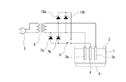
本発明に係る硝酸性窒素の除去方法に用いることができる実施例1の電気回路を図1に示してある。処理槽1に収容された処理対象となる液体2中には、一対の交流電極3a、3bと、該一対の交流電極3a、3bに近接させた少なくとも1つの接地電極4とを配設している。この処理槽1は、必ずしも容器状の処理槽である必要はなく、例えば、貯水湖または浄水場等の液体2が貯水された施設等であっても良い。
Next, the present invention will be described in detail based on specific examples.
An electric circuit of Example 1 that can be used in the method for removing nitrate nitrogen according to the present invention is shown in FIG. In the
また、液体2としては、例えば、一般的な水道水等の飲料水、貯水湖または浄水場等に貯水された水、地下水、家庭の生活排水、工場排水またはミネラルウォーター等の液体を処理対象として用いるものである。
In addition, as the
一対の交流電極3a、3bとしては、例えば、チタン、亜鉛、アルミニウム合金、鉄、コバルト、ニッケル、錫またはマグネシウム合金等の溶解性の高い金属を使用することができ、また、接地電極4としては、例えば、チタン、パラジウム、銀、亜鉛、アルミニウム、銅、真鍮、カーボン、ニッケル、鉄、コバルトまたはステンレス鋼等のイオン化傾向の高い金属を使用することができる。
As the pair of
一対の交流電極3a、3bは、例えば、一時側がACコード5に接続している変圧器6の二次側に接続されており、前記ACコード5から供給された交流電圧を変圧器6により所定の電圧に変換して、該交流電圧を一対の交流電極3a、3b間に印加できるようになっている。
The pair of
また、変圧器6の二次側のそれぞれの配線には、ダイオード7a、7bのカソード側が接続されており、該ダイオード7a、7bのアノード側には、接地電極4が接続されている。そのため、接地電極4は、実質的に接地の電位になっている。
Further, the cathodes of the
処理槽1の底部には、加熱手段8が配設されており、該加熱手段8により前記処理槽1内に収容された液体2を所定の温度に加熱することができるようになっている。この液体2の所定の温度としては、略30℃以上の温度であることが好ましい。
A
この加熱手段8は、必要に応じて用いれば良く、液体2の温度が予め略30℃以上であるような場合には、省略しても良い。この液体2の温度としては、略30℃以上であれば良く、略40℃〜略65℃程度にすることが好ましい。
The heating means 8 may be used as necessary, and may be omitted when the temperature of the
また、液体2の温度が略30℃以下であっても、一対の交流電極3a、3bに交流を印加し、該交流による電気分解が行われる際に前記一対の交流電極3a、3bから発生する熱によって、前記液体2を加熱することができるため、短時間で処理の効果を得ることを目的としないような場合には、必ずしも加熱手段8を配設する必要はないのである。
Further, even when the temperature of the
このように、液体2の温度を略30℃以上にすることにより、前記一対の交流電極3a、3b間に交流を印加し、前記液体2を交流電気分解する際に、該液体2中に含有される酸素が脱気されるようになるのである。
Thus, when the temperature of the
そして、ACコード5を図示していない交流電源に接続させることにより、一対の交流電極3a、3b間に交流が印加されるようになり、該一対の交流電極3a、3b及び/または接地電極4から水素(水素イオン、原子状水素)が発生するようになる。
Then, by connecting the
このように、一対の交流電極3a、3b間に交流を印加することにより、該交流で液体2を電気分解して、該液体2に電気化学的還元を生じさせることができると共に、該液体2中に水素(水素イオン、原子状水素)を発生させることにより、発生させた該水素が前記液体2中に含まれる硝酸性窒素と反応して還元されるようになる。この際、液体2中では、接地電極4側で下記のような反応が生ずることになる。
In this way, by applying an alternating current between the pair of
また、ダイオード7a、7bと接地電極4との間に切り換えスイッチ9を接続すると共に、変圧器6の二次側のそれぞれの配線にダイオード10a、10bのアノード側を接続させ、該ダイオード10a、10bのカソード側を前記切り換えスイッチ9の他方の端子に接続し、該切り換えスイッチ9により切り換えられるようにしても良い。
Further, the
この切り換えスイッチ9を切り換えるのは、液体2の硝酸性窒素分解終了時であり、該硝酸性窒素分解終了時に発生するアンモニアを分解するために数分〜数時間接地電極4をプラスの電位にして、液体2中のアンモニアを分解させるのである。
The
水素イオンの還元反応
(式1)(主に電気化学的還元)
2H+ + 2e → 2H → H2
Reduction reaction of hydrogen ion (formula 1) (mainly electrochemical reduction)
2H + + 2e → 2H → H 2
硝酸イオンの還元反応
(式2)(主に電気化学的還元)
NO− 3 + 2H+ + 2e → NO− 2 + H2O
Reduction reaction of nitrate ion (formula 2) (mainly electrochemical reduction)
NO − 3 + 2H + + 2e → NO − 2 + H 2 O
亜硝酸イオンの還元反応
(式3)(主に電気化学的還元)
2NO− 2 + 8H+ + 6e → N2 + 4H2O
(式4)(主に電気化学的還元)
NO− 2 + 4H+ + 2e → NH+ 4 + 2H2O
Reduction reaction of nitrite ion (Formula 3) (mainly electrochemical reduction)
2NO − 2 + 8H + + 6e → N 2 + 4H 2 O
(Formula 4) (Mainly electrochemical reduction)
NO - 2 + 4H + + 2e → NH + 4 + 2H 2 O
更に、確認されてはいないが、液体2中の接地電極4側では、水素(水素イオン、原子状水素)により下記のような反応が生じていることも考えられる。
Further, although not confirmed, the following reaction may be caused by hydrogen (hydrogen ions, atomic hydrogen) on the
(式5)(主に化学的還元)
NO− 3 + 2H → NO2 − + H2O
(式6)(主に化学的還元)
2NO− 2 + 6H + 2H+ → N2 + 4H2O
(式7)(主に化学的還元)
NO− 2 + 6H + 2H+ → NH+ 4 + 2H2O
(Formula 5) (mainly chemical reduction)
NO - 3 + 2H → NO 2 - + H 2 O
(Formula 6) (mainly chemical reduction)
2NO − 2 + 6H + 2H + → N 2 + 4H 2 O
(Formula 7) (mainly chemical reduction)
NO - 2 + 6H + 2H + → NH + 4 + 2H 2 O
また、従来の直流による電気分解と異なり、交流による電気分解においては、液体2中の一対の交流電極3a、3b側では、下記式8のような反応も生ずることになる。
Further, unlike the conventional direct current electrolysis, in the alternating current electrolysis, a reaction represented by the
アンモニウムイオンの酸化反応
(式8)
NH+ 4 + 4OH− → 1/2N2 + 4H2O + 3e
Ammonium ion oxidation reaction (Formula 8)
NH + 4 + 4OH − → 1 / 2N 2 + 4H 2 O + 3e
また、液体2中に塩素イオン(Cl−)が含まれると、一対の交流電極3a、3bによって該塩素イオンが酸化されて次亜塩素酸イオン(ClO−)が生じるか、または、前記塩素イオンが酸化されてCl2が生じ、該Cl2が不均化反応により次亜塩素酸イオンになる。そして、アンモニアイオンは、次亜塩素酸イオンによって酸化され、N2ガスになる。
Further, when chlorine ions (Cl − ) are contained in the
(式9)
2NH+ 4 + 3ClO− → N2 + 2H+ + 3Cl− + 3H2O
(Formula 9)
2NH + 4 + 3ClO − → N 2 + 2H + + 3Cl − + 3H 2 O
従って、従来技術のように処理槽1内を2つに分離して、処理対象の液体2を陽極側と陰極側とに分離させる必要がないため、例えば、貯水湖または浄水場等の液体を特別な収容部内等に移動させず、そのままの状態であっても、硝酸性窒素が交流によって電気化学的に電気分解が行われると共に、一対の交流電極3a、3b及び/または接地電極4から発生された水素(水素イオン、原子状水素)と、硝酸性窒素とが化学的に反応して、硝酸性窒素が還元されることにより、前記貯水湖または浄水場等の液体中に含有される硝酸性窒素を除去することができ、その際、一対の交流電極3a、3bに印加される電圧は、プラスとマイナスとが交互に繰り返されるため、処理後の液体2の性質が変化することがないのである。
Therefore, it is not necessary to separate the treatment tank 1 into two parts and separate the
そして、この交流電気分解の際に生ずる酸素は、前述のように液体2を所定の温度に加熱することにより、該液体2から酸素が脱気されていると共に、残存する酸素は前記溶解性の高い金属から形成されている一対の交流電極3a、3bと反応するため、液体2中には、酸素分子として殆ど存在しないことになり、水素と、硝酸性窒素との反応の妨げになることはないのである。
The oxygen generated during the AC electrolysis is degassed from the
また、この実施例1の電気回路において、該電気回路に電源を供給する方法として、ACコード5を交流電源に接続しているが、前記電気回路に電源を供給する方法は、これに限定されるものではなく、例えば、直流電源(例えば電池等)を用い、該直流電源を交流に変換する回路を形成して一対の交流電極3a、3bに交流を印加できるようにしても良い。
In the electric circuit of the first embodiment, the
そのため、電源として、例えば電池を用い、同一出願人に係る特許第3325081号公報に記載されたようなフロート状の装置に本発明に係る硝酸性窒素の除去方法を用いることにより、貯水湖または浄水場等に貯水された液体に前記フロート状の装置を浮かべておくだけで、前記液体2から硝酸性窒素を容易に除去できるようになるのである。
Therefore, by using, for example, a battery as a power source and using the method for removing nitrate nitrogen according to the present invention in a float-type device as described in Japanese Patent No. 3325081 related to the same applicant, The nitrate nitrogen can be easily removed from the
更に、接地電極4を周期的に一対の交流電極3a、3bに供給される交流の配線に接続して周期的に交流を印加する、または、周期的に前記直流電源のプラス側に接続して周期的に接地の電位からプラスの電位にすることにより、前記接地電極4に吸着したスケール等を除去してクリーニングできるようになるため、該接地電極4から発生する水素の量が低下することなく、該水素の発生量を安定して維持できるのである。ほか、液体2中に酸素を補給し、アンモニア(NH4)の分解も可能にする。
Further, the
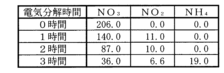
次に、本発明に係る硝酸性窒素の除去方法を用いて、液体中に含有される硝酸性窒素が除去されることを確認する試験を行った結果を以下に示す。なお、これら試験においては、一対の交流電極として、亜鉛板を用い、接地電極として、真鍮板を用いたものである。また、液体として、水道水に硝酸を混合させて、該液体中に含有される硝酸が略200ppm程度になるように調整して用いたものであり、そのため、硝酸性窒素として、特に硝酸の除去・減少を確認することにより、硝酸性窒素の除去・減少についても確認しているものである。 Next, the result of having performed the test which confirms that the nitrate nitrogen contained in a liquid is removed using the removal method of nitrate nitrogen which concerns on this invention is shown below. In these tests, a zinc plate was used as the pair of AC electrodes, and a brass plate was used as the ground electrode. In addition, as a liquid, tap water is mixed with nitric acid so that the nitric acid contained in the liquid is adjusted to about 200 ppm. Therefore, as nitrate nitrogen, particularly nitric acid is removed. -By confirming the decrease, removal and reduction of nitrate nitrogen are also confirmed.
(試験1)
この試験1においては、液体の温度を略31℃程度に加熱した。この液体は、略pH4程度であった。この試験1により硝酸性窒素(特に硝酸)の除去・減少を確認した結果を表1に示す。
(Test 1)
In Test 1, the temperature of the liquid was heated to about 31 ° C. This liquid was about
(試験2)
この試験2においては、液体の温度を略12℃程度のものを用いた。この液体は、略pH11.1程度であった。この試験2により硝酸性窒素(特に硝酸)の除去・減少を確認した結果を表2に示す。
(Test 2)
In
(試験3)
この試験3においては、液体を沸騰させた後、冷却して温度が略31℃程度に低下したものを用いた。この液体は、略pH11.2程度であった。この試験3により硝酸性窒素(特に硝酸)の除去・減少を確認した結果を表3に示す。
(Test 3)
In Test 3, the liquid was boiled and then cooled and the temperature dropped to about 31 ° C. This liquid was about pH 11.2. Table 3 shows the results of confirming removal / reduction of nitrate nitrogen (particularly nitric acid) by Test 3.
(試験4)
この試験4においては、液体の温度を略65℃程度に加熱した。この液体は、略pH11.0程度であった。この試験4により硝酸性窒素(特に硝酸)の除去・減少を確認した結果を表4に示す。
(Test 4)
In
(試験5)
この試験5においては、液体の温度が略31℃程度であった。この液体は、略pH9.0程度であった。この試験5により硝酸性窒素(特に硝酸)の除去・減少を確認した結果を表5に示す。
(Test 5)
In
(試験6)
この試験6においては、液体の温度を略39℃程度に加熱した。この液体は、略pH6程度であった。この試験6により硝酸性窒素(特に硝酸)の除去・減少を確認した結果を表6に示す。
(Test 6)
In this
(試験7)
この試験7においては、液体の温度を略37℃程度に加熱した。この液体は、略pH6程度であった。この試験7により硝酸性窒素(特に硝酸)の除去・減少を確認した結果を表7に示す。
(Test 7)
In this test 7, the temperature of the liquid was heated to about 37 ° C. This liquid was about
(試験8)
この試験8においては、液体の温度を略32℃程度に加熱した。この液体は、略pH4程度であった。この試験8により硝酸性窒素(特に硝酸)の除去・減少を確認した結果を表8に示す。
(Test 8)
In
これら表1乃至表8から明らかなように、本発明に係る硝酸性窒素の除去方法を用いることにより、液体中に含まれる硝酸(硝酸性窒素)を除去・減少させることができ、特に、液体の温度を略30℃以上にしたときに効率良く液体中に含まれる硝酸(硝酸性窒素)を除去・減少できることが理解できる。 As is apparent from Tables 1 to 8, by using the method for removing nitrate nitrogen according to the present invention, nitric acid (nitrate nitrogen) contained in the liquid can be removed and reduced. It can be understood that nitric acid (nitric nitrogen) contained in the liquid can be efficiently removed / reduced when the temperature of is about 30 ° C. or higher.
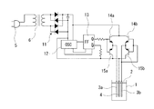
次に、本発明に係る硝酸性窒素の除去方法に用いることができる実施例2の電気回路を図2に示してある。なお、この実施例2においては、前記実施例1の一対の交流電極3a、3bにトランジスタから構成される高周波スイッチを接続させ、また、加熱手段を省略したものであり、その他の構成については、前記実施例1と実質的に同一であるため、前記実施例1と実質的に同一の部分については、同一の符号を付し、説明が重複するため、その詳細な説明については省略する。
Next, FIG. 2 shows an electric circuit of Example 2 that can be used in the method for removing nitrate nitrogen according to the present invention. In the second embodiment, the pair of
この実施例2においては、前記実施例1で用いていた加熱手段を省略してある。このように、加熱手段を省略した場合であっても、交流電気分解時に一対の交流電極3a、3bから生ずる熱によって、液体2は加熱されるのである。
In the second embodiment, the heating means used in the first embodiment is omitted. Thus, even when the heating means is omitted, the
実施例2においては、ACコード5が変圧器6の一次側に接続され、該変圧器6の二次側には、ダイオードブリッジ回路11が接続されているため、前記ACコード5から供給される交流は、前記ダイオードブリッジ回路11により整流されて略直流に変換される。
In the second embodiment, the
このダイオードブリッジ回路11には、高周波発振器12が接続されており、前記ダイオードブリッジ回路11を介して一旦略直流に変換された後、前記高周波発振器12により高周波の交流に変換される。
A high-
この高周波発振器12には、フリップフロップ回路よりなる高周波切換指令回路13が接続されており、該高周波切換指令回路13により高周波の切換が行われ、該切り換えられた高周波の交流は、前記高周波切換指令回路13に接続したトランジスタ14a、15aと、14b、15bとから構成された高周波スイッチに入力され、該高周波スイッチを介して一対の交流電極3a、3bに印加される。
The high-
このように、本発明に係る硝酸性窒素の除去方法に用いる電気回路としては、ACコード5から供給される交流を直接的に用いるばかりでなく、高周波の交流に変換して用いても良く、また、該交流の周波数を時系的に変化させても良いのである。
As described above, as an electric circuit used in the method for removing nitrate nitrogen according to the present invention, not only the alternating current supplied from the
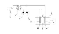
次に、本発明に係る硝酸性窒素の除去方法に用いることができる実施例3の電気回路を図3に示してある。なお、この実施例3においては、前記実施例1に脱気装置を配設したものであり、その他の構成については、前記実施例1と実質的に同一であるため、前記実施例1と実質的に同一の部分については、同一の符号を付し、説明が重複するため、その詳細な説明については省略する。 Next, FIG. 3 shows an electric circuit of Example 3 that can be used in the method for removing nitrate nitrogen according to the present invention. In the third embodiment, a deaeration device is provided in the first embodiment, and the other configurations are substantially the same as those in the first embodiment. Therefore, the third embodiment is substantially the same as the first embodiment. The same parts are denoted by the same reference numerals, and the description thereof is duplicated, so that the detailed description thereof is omitted.
この実施例3においては、前記実施例1に脱気装置21として、減圧室に半透明膜状のパイプ(電極カバー)を一対の交流電極3a、3bのそれぞれの周囲に配設したものである。この脱気装置21としては、前記半透明膜状のパイプ(電極カバー)以外にも、例えば、窒素ガスのバブリング装置等を使用することができ、また、脱気装置21を用いなくても、液体2を加熱して脱気するだけであっても良い。
In the third embodiment, as the
このように、液体2中の酸素を脱気することによって、一対の交流電極3a、3b及び/または接地電極4から発生された水素と、硝酸性窒素との反応がよりスムーズに行われるようになるのである。
As described above, by degassing oxygen in the
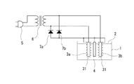
次に、本発明に係る硝酸性窒素の除去方法に用いることができる実施例4の電気回路を図4に示してある。なお、この実施例4においては、前記実施例1に脱気装置を配設したものであり、その他の構成については、前記実施例1と実質的に同一であるため、前記実施例1と実質的に同一の部分については、同一の符号を付し、説明が重複するため、その詳細な説明については省略する。 Next, FIG. 4 shows an electric circuit of Example 4 that can be used in the method for removing nitrate nitrogen according to the present invention. In the fourth embodiment, the deaeration device is provided in the first embodiment, and the other configurations are substantially the same as those in the first embodiment. Therefore, the fourth embodiment is substantially the same as the first embodiment. The same parts are denoted by the same reference numerals, and the description thereof is duplicated, so that the detailed description thereof is omitted.
この実施例4においては、前記実施例1に脱気装置31として、ステンレスまたはチタン等の金属からなる網状のパイプ(電極カバー)を一対の交流電極3a、3bのそれぞれの周囲に配設して、接地電極4と同電位にしたものである。
In the fourth embodiment, a net-like pipe (electrode cover) made of a metal such as stainless steel or titanium is disposed around each of the pair of
このように脱気装置31は接地の電位にしてあるため、一対の交流電極3a、3bから発生した酸素が網状パイプからなる脱気装置31に吸着されるようになるため、液体2中の酸素が脱気されて、一対の交流電極3a、3b及び/または接地電極4から発生された水素と、硝酸性窒素との反応がよりスムーズに行われるようになるのである。
As described above, since the
なお、本発明に係る硝酸性窒素の除去方法により、液体2中に金属イオンが生じた場合には、各種凝集剤等を用いることによって沈殿させたり、除去フィルターを用いたりすることによって、除去することができる。
In addition, when metal ions are generated in the
1 処理槽
2 液体
3a、3b 一対の交流電極
4 接地電極
5 ACコード
6 変圧器
7a、7b、10a、10b ダイオード
8 加熱手段
9 切り換えスイッチ
11 ダイオードブリッジ回路
12 高周波発振器
13 高周波切換指令回路
14a、15a、14b、15b トランジスタ
21、31 脱気装置(電極カバー)
DESCRIPTION OF SYMBOLS 1
Claims (7)
前記液体中に一対の交流電極と、該一対の交流電極に近接させた少なくとも1つの接地電極とを配設し、
前記液体を所定の温度に加熱し、
前記一対の交流電極間に交流を印加し電気分解して電気化学的還元を行うと共に、
該一対の交流電極及び/または前記接地電極から水素を発生させ該水素が硝酸性窒素と反応することにより硝酸性窒素を除去すること
を特徴とする硝酸性窒素の除去方法。 A method of removing nitrate nitrogen contained in a liquid by electrochemical reduction and hydrogen reduction,
A pair of alternating electrodes in the liquid and at least one ground electrode disposed close to the pair of alternating electrodes;
Heating the liquid to a predetermined temperature;
While applying an alternating current between the pair of alternating electrodes to perform electrolysis and electrochemical reduction,
A method for removing nitrate nitrogen, wherein hydrogen is generated from the pair of AC electrodes and / or the ground electrode, and the hydrogen reacts with nitrate nitrogen to remove nitrate nitrogen.
前記接地電極は、チタン、パラジウム、銀、亜鉛、アルミニウム、銅、真鍮、カーボン、ニッケル、鉄、コバルトまたはステンレス鋼であること
を特徴とする請求項1に記載の硝酸性窒素の除去方法。 The pair of AC electrodes is titanium, zinc, aluminum alloy, iron, cobalt, nickel, tin, or magnesium alloy,
The method for removing nitrate nitrogen according to claim 1, wherein the ground electrode is titanium, palladium, silver, zinc, aluminum, copper, brass, carbon, nickel, iron, cobalt, or stainless steel.
周期的に接地の電位から交流を印加またはプラスの電位にすること
を特徴とする請求項1または2に記載の硝酸性窒素の除去方法。 The ground electrode is
The method for removing nitrate nitrogen according to claim 1 or 2, wherein alternating current is applied periodically from a ground potential or is made a positive potential.
加熱手段または一対の交流電極から発生する熱により行うこと
を特徴とする請求項1に記載の硝酸性窒素の除去方法。 The heating of the liquid is
The method for removing nitrate nitrogen according to claim 1, wherein the removal is performed by heat generated from a heating means or a pair of AC electrodes.
液体の温度が略30℃以上であること
を特徴とする請求項1に記載の硝酸性窒素の除去方法。 The predetermined temperature is
The method for removing nitrate nitrogen according to claim 1, wherein the temperature of the liquid is approximately 30 ° C. or higher.
含有する酸素を脱気すること
を特徴とする請求項1、4または5に記載の硝酸性窒素の除去方法。 The liquid is
The method for removing nitrate nitrogen according to claim 1, wherein the oxygen contained is degassed.
を特徴とする請求項1に記載の硝酸性窒素の除去方法。 The method for removing nitrate nitrogen according to claim 1, wherein the ground electrode is set to a positive potential for several minutes to several hours for the decomposition of ammonia generated at the end of the decomposition of nitrate nitrogen.
Priority Applications (1)
| Application Number | Priority Date | Filing Date | Title |
|---|---|---|---|
| JP2004114121A JP4532967B2 (en) | 2004-04-08 | 2004-04-08 | How to remove nitrate nitrogen |
Applications Claiming Priority (1)
| Application Number | Priority Date | Filing Date | Title |
|---|---|---|---|
| JP2004114121A JP4532967B2 (en) | 2004-04-08 | 2004-04-08 | How to remove nitrate nitrogen |
Publications (2)
| Publication Number | Publication Date |
|---|---|
| JP2005296743A true JP2005296743A (en) | 2005-10-27 |
| JP4532967B2 JP4532967B2 (en) | 2010-08-25 |
Family
ID=35328941
Family Applications (1)
| Application Number | Title | Priority Date | Filing Date |
|---|---|---|---|
| JP2004114121A Expired - Lifetime JP4532967B2 (en) | 2004-04-08 | 2004-04-08 | How to remove nitrate nitrogen |
Country Status (1)
| Country | Link |
|---|---|
| JP (1) | JP4532967B2 (en) |
Cited By (7)
| Publication number | Priority date | Publication date | Assignee | Title |
|---|---|---|---|---|
| JP2006239531A (en) * | 2005-03-02 | 2006-09-14 | Hideo Hayakawa | Water purification method using sodium hypochlorite |
| JP2009022927A (en) * | 2007-07-23 | 2009-02-05 | Silver Seiko Ltd | Reduced hydrogen water generator |
| CN102910708A (en) * | 2012-10-31 | 2013-02-06 | 武汉玻尔科技有限公司 | Electrochemical combined anode treatment method for industrial waste water |
| CN105417800A (en) * | 2016-01-08 | 2016-03-23 | 四川师范大学 | Environment-friendly method for removing nitrate nitrogen in waste water |
| CN105417647A (en) * | 2016-01-08 | 2016-03-23 | 四川师范大学 | Method for removing nitrate nitrogen in water with thermometal as reducing agent |
| CN105621759A (en) * | 2016-01-08 | 2016-06-01 | 四川师范大学 | Method for efficiently and environmentally removing nitrogen nitrate in water |
| CN114105259A (en) * | 2021-12-01 | 2022-03-01 | 南京环保产业创新中心有限公司 | Cu-Co-PAC particle electrode, preparation method and application thereof |
Citations (8)
| Publication number | Priority date | Publication date | Assignee | Title |
|---|---|---|---|---|
| JPS5513116A (en) * | 1978-07-14 | 1980-01-30 | Hitachi Ltd | Purification of night soil treated water |
| JP2003164877A (en) * | 2001-12-03 | 2003-06-10 | Sanyo Electric Co Ltd | Method for treating nitrogen |
| JP2003190958A (en) * | 2001-12-27 | 2003-07-08 | Sanyo Electric Co Ltd | Method and apparatus for treating nitrogen |
| JP2003220390A (en) * | 2002-01-31 | 2003-08-05 | Permelec Electrode Ltd | Method for treating nitric nitrogen and catalyst and structure used therefor |
| JP2003230883A (en) * | 2002-02-08 | 2003-08-19 | Sanyo Electric Co Ltd | Wastewater treatment method and wastewater treatment system |
| JP2003236543A (en) * | 2002-02-14 | 2003-08-26 | Hideo Hayakawa | Alternating current electrolysis method and apparatus for liquid |
| JP2003311274A (en) * | 2002-02-25 | 2003-11-05 | Sanyo Electric Co Ltd | Water treatment apparatus |
| JP2004097950A (en) * | 2002-09-10 | 2004-04-02 | Sanyo Electric Co Ltd | Wastewater treatment apparatus and wastewater treatment system |
-
2004
- 2004-04-08 JP JP2004114121A patent/JP4532967B2/en not_active Expired - Lifetime
Patent Citations (8)
| Publication number | Priority date | Publication date | Assignee | Title |
|---|---|---|---|---|
| JPS5513116A (en) * | 1978-07-14 | 1980-01-30 | Hitachi Ltd | Purification of night soil treated water |
| JP2003164877A (en) * | 2001-12-03 | 2003-06-10 | Sanyo Electric Co Ltd | Method for treating nitrogen |
| JP2003190958A (en) * | 2001-12-27 | 2003-07-08 | Sanyo Electric Co Ltd | Method and apparatus for treating nitrogen |
| JP2003220390A (en) * | 2002-01-31 | 2003-08-05 | Permelec Electrode Ltd | Method for treating nitric nitrogen and catalyst and structure used therefor |
| JP2003230883A (en) * | 2002-02-08 | 2003-08-19 | Sanyo Electric Co Ltd | Wastewater treatment method and wastewater treatment system |
| JP2003236543A (en) * | 2002-02-14 | 2003-08-26 | Hideo Hayakawa | Alternating current electrolysis method and apparatus for liquid |
| JP2003311274A (en) * | 2002-02-25 | 2003-11-05 | Sanyo Electric Co Ltd | Water treatment apparatus |
| JP2004097950A (en) * | 2002-09-10 | 2004-04-02 | Sanyo Electric Co Ltd | Wastewater treatment apparatus and wastewater treatment system |
Cited By (8)
| Publication number | Priority date | Publication date | Assignee | Title |
|---|---|---|---|---|
| JP2006239531A (en) * | 2005-03-02 | 2006-09-14 | Hideo Hayakawa | Water purification method using sodium hypochlorite |
| JP2009022927A (en) * | 2007-07-23 | 2009-02-05 | Silver Seiko Ltd | Reduced hydrogen water generator |
| CN102910708A (en) * | 2012-10-31 | 2013-02-06 | 武汉玻尔科技有限公司 | Electrochemical combined anode treatment method for industrial waste water |
| CN105417800A (en) * | 2016-01-08 | 2016-03-23 | 四川师范大学 | Environment-friendly method for removing nitrate nitrogen in waste water |
| CN105417647A (en) * | 2016-01-08 | 2016-03-23 | 四川师范大学 | Method for removing nitrate nitrogen in water with thermometal as reducing agent |
| CN105621759A (en) * | 2016-01-08 | 2016-06-01 | 四川师范大学 | Method for efficiently and environmentally removing nitrogen nitrate in water |
| CN114105259A (en) * | 2021-12-01 | 2022-03-01 | 南京环保产业创新中心有限公司 | Cu-Co-PAC particle electrode, preparation method and application thereof |
| CN114105259B (en) * | 2021-12-01 | 2024-06-11 | 南京环保产业创新中心有限公司 | Cu-Co-PAC particle electrode, preparation method and application thereof |
Also Published As
| Publication number | Publication date |
|---|---|
| JP4532967B2 (en) | 2010-08-25 |
Similar Documents
| Publication | Publication Date | Title |
|---|---|---|
| EP3162768B1 (en) | Resource reuse-type industrial waste water treatment method and apparatus utilizing oxidizing agent generated by utilizing waste water | |
| JP2623204B2 (en) | Water reforming method | |
| Khelifa et al. | A one-step electrochlorination/electroflotation process for the treatment of heavy metals wastewater in presence of EDTA | |
| CN101198551B (en) | Electrolytic treatment method and device for wastewater containing ammonia nitrogen | |
| KR20090024274A (en) | Process for water treatment for cooling towers and processes requiring integrated systems and removal of silica from water | |
| JP4532967B2 (en) | How to remove nitrate nitrogen | |
| WO2013176111A1 (en) | Processing method and apparatus for copper chloride-containing acidic waste liquids | |
| KR100311951B1 (en) | Apparatus and method for treating a cyanide waste water using a electrolysis | |
| MXPA02001937A (en) | Electrolytic phosphate chemical treatment method. | |
| JP2009160486A (en) | Processing equipment for copper etching waste liquid containing hydrogen peroxide | |
| Lippert et al. | Electrochemical Innovations for sustainable copper management in semiconductor wastewater | |
| WO2009133550A1 (en) | Integrated electrolytic and chemical method for producing clean treated water wherein cyanide species concentration is less than 1 milligram per liter | |
| JP3193833U (en) | Hydrogen water generator | |
| JP4511204B2 (en) | Reduced water generator | |
| JP5122074B2 (en) | Water treatment method and system | |
| JP2012040524A (en) | Electrolytic treatment apparatus and electrolytic treatment method | |
| JP4071980B2 (en) | Method and apparatus for cleaning electronic parts | |
| JP4053805B2 (en) | Functional water, production method and production apparatus thereof | |
| JP2009035442A (en) | Diamond processing method | |
| JP4038253B2 (en) | Electrolyzer for production of acidic water and alkaline water | |
| Soeprijanto et al. | Treatment of oily bilge water by electrocoagulation process using aluminum electrodes | |
| JP6528326B2 (en) | Water treatment equipment | |
| KR20040086096A (en) | Electrochemical process for wastewater containing nitric acid | |
| Shanthi et al. | Domestic sewage treatment using batch stirred tank electrochemical reactor | |
| Lee et al. | Removal of ammonium and fluoride from industrial wastewater by sonoelectrochemical precipitation |
Legal Events
| Date | Code | Title | Description |
|---|---|---|---|
| A621 | Written request for application examination |
Free format text: JAPANESE INTERMEDIATE CODE: A621 Effective date: 20070404 |
|
| A977 | Report on retrieval |
Free format text: JAPANESE INTERMEDIATE CODE: A971007 Effective date: 20080919 |
|
| A131 | Notification of reasons for refusal |
Free format text: JAPANESE INTERMEDIATE CODE: A131 Effective date: 20100216 |
|
| A521 | Request for written amendment filed |
Free format text: JAPANESE INTERMEDIATE CODE: A523 Effective date: 20100408 |
|
| TRDD | Decision of grant or rejection written | ||
| A01 | Written decision to grant a patent or to grant a registration (utility model) |
Free format text: JAPANESE INTERMEDIATE CODE: A01 Effective date: 20100513 |
|
| A01 | Written decision to grant a patent or to grant a registration (utility model) |
Free format text: JAPANESE INTERMEDIATE CODE: A01 |
|
| A61 | First payment of annual fees (during grant procedure) |
Free format text: JAPANESE INTERMEDIATE CODE: A61 Effective date: 20100611 |
|
| R150 | Certificate of patent or registration of utility model |
Ref document number: 4532967 Country of ref document: JP Free format text: JAPANESE INTERMEDIATE CODE: R150 Free format text: JAPANESE INTERMEDIATE CODE: R150 |
|
| FPAY | Renewal fee payment (event date is renewal date of database) |
Free format text: PAYMENT UNTIL: 20130618 Year of fee payment: 3 |
|
| R250 | Receipt of annual fees |
Free format text: JAPANESE INTERMEDIATE CODE: R250 |
|
| R250 | Receipt of annual fees |
Free format text: JAPANESE INTERMEDIATE CODE: R250 |
|
| R250 | Receipt of annual fees |
Free format text: JAPANESE INTERMEDIATE CODE: R250 |
|
| S111 | Request for change of ownership or part of ownership |
Free format text: JAPANESE INTERMEDIATE CODE: R313111 |
|
| R350 | Written notification of registration of transfer |
Free format text: JAPANESE INTERMEDIATE CODE: R350 |
|
| S201 | Request for registration of exclusive licence |
Free format text: JAPANESE INTERMEDIATE CODE: R314201 |
|
| R350 | Written notification of registration of transfer |
Free format text: JAPANESE INTERMEDIATE CODE: R350 |
|
| R250 | Receipt of annual fees |
Free format text: JAPANESE INTERMEDIATE CODE: R250 |
|
| R250 | Receipt of annual fees |
Free format text: JAPANESE INTERMEDIATE CODE: R250 |
|
| R250 | Receipt of annual fees |
Free format text: JAPANESE INTERMEDIATE CODE: R250 |
|
| R250 | Receipt of annual fees |
Free format text: JAPANESE INTERMEDIATE CODE: R250 |
|
| R250 | Receipt of annual fees |
Free format text: JAPANESE INTERMEDIATE CODE: R250 |
|
| R250 | Receipt of annual fees |
Free format text: JAPANESE INTERMEDIATE CODE: R250 |
|
| R250 | Receipt of annual fees |
Free format text: JAPANESE INTERMEDIATE CODE: R250 |
|
| R250 | Receipt of annual fees |
Free format text: JAPANESE INTERMEDIATE CODE: R250 |
|
| EXPY | Cancellation because of completion of term |