JP2005296723A - Applicator - Google Patents
Applicator Download PDFInfo
- Publication number
- JP2005296723A JP2005296723A JP2004112927A JP2004112927A JP2005296723A JP 2005296723 A JP2005296723 A JP 2005296723A JP 2004112927 A JP2004112927 A JP 2004112927A JP 2004112927 A JP2004112927 A JP 2004112927A JP 2005296723 A JP2005296723 A JP 2005296723A
- Authority
- JP
- Japan
- Prior art keywords
- web
- applicator roll
- ejector
- box
- coating
- Prior art date
- Legal status (The legal status is an assumption and is not a legal conclusion. Google has not performed a legal analysis and makes no representation as to the accuracy of the status listed.)
- Withdrawn
Links
- 238000000576 coating method Methods 0.000 claims abstract description 237
- 239000011248 coating agent Substances 0.000 claims abstract description 236
- 238000011144 upstream manufacturing Methods 0.000 claims abstract description 74
- 239000007788 liquid Substances 0.000 claims description 84
- 230000002265 prevention Effects 0.000 claims description 38
- XLYOFNOQVPJJNP-UHFFFAOYSA-N water Substances O XLYOFNOQVPJJNP-UHFFFAOYSA-N 0.000 claims description 6
- 239000003595 mist Substances 0.000 abstract description 6
- 230000015572 biosynthetic process Effects 0.000 abstract 1
- 239000007789 gas Substances 0.000 description 48
- 230000000694 effects Effects 0.000 description 36
- 238000009833 condensation Methods 0.000 description 8
- 230000005494 condensation Effects 0.000 description 8
- 238000002347 injection Methods 0.000 description 8
- 239000007924 injection Substances 0.000 description 8
- 230000002093 peripheral effect Effects 0.000 description 8
- 239000000243 solution Substances 0.000 description 6
- 238000001179 sorption measurement Methods 0.000 description 5
- 239000011261 inert gas Substances 0.000 description 4
- 230000001070 adhesive effect Effects 0.000 description 3
- 230000006872 improvement Effects 0.000 description 3
- 230000008929 regeneration Effects 0.000 description 3
- 238000011069 regeneration method Methods 0.000 description 3
- IJGRMHOSHXDMSA-UHFFFAOYSA-N Atomic nitrogen Chemical compound N#N IJGRMHOSHXDMSA-UHFFFAOYSA-N 0.000 description 2
- 229910000831 Steel Inorganic materials 0.000 description 2
- 239000000853 adhesive Substances 0.000 description 2
- 230000008859 change Effects 0.000 description 2
- 238000007599 discharging Methods 0.000 description 2
- 239000002184 metal Substances 0.000 description 2
- 238000000034 method Methods 0.000 description 2
- 230000035515 penetration Effects 0.000 description 2
- 230000001737 promoting effect Effects 0.000 description 2
- 239000007921 spray Substances 0.000 description 2
- 239000010959 steel Substances 0.000 description 2
- 238000009423 ventilation Methods 0.000 description 2
- 238000004804 winding Methods 0.000 description 2
- 238000010521 absorption reaction Methods 0.000 description 1
- 230000002411 adverse Effects 0.000 description 1
- 238000006243 chemical reaction Methods 0.000 description 1
- 238000007766 curtain coating Methods 0.000 description 1
- 238000001035 drying Methods 0.000 description 1
- 229910052757 nitrogen Inorganic materials 0.000 description 1
- 239000011148 porous material Substances 0.000 description 1
- 230000008569 process Effects 0.000 description 1
- 230000001172 regenerating effect Effects 0.000 description 1
- 239000012224 working solution Substances 0.000 description 1
Images

Classifications
-
- B—PERFORMING OPERATIONS; TRANSPORTING
- B05—SPRAYING OR ATOMISING IN GENERAL; APPLYING FLUENT MATERIALS TO SURFACES, IN GENERAL
- B05C—APPARATUS FOR APPLYING FLUENT MATERIALS TO SURFACES, IN GENERAL
- B05C1/00—Apparatus in which liquid or other fluent material is applied to the surface of the work by contact with a member carrying the liquid or other fluent material, e.g. a porous member loaded with a liquid to be applied as a coating
- B05C1/04—Apparatus in which liquid or other fluent material is applied to the surface of the work by contact with a member carrying the liquid or other fluent material, e.g. a porous member loaded with a liquid to be applied as a coating for applying liquid or other fluent material to work of indefinite length
- B05C1/08—Apparatus in which liquid or other fluent material is applied to the surface of the work by contact with a member carrying the liquid or other fluent material, e.g. a porous member loaded with a liquid to be applied as a coating for applying liquid or other fluent material to work of indefinite length using a roller or other rotating member which contacts the work along a generating line
- B05C1/086—Apparatus in which liquid or other fluent material is applied to the surface of the work by contact with a member carrying the liquid or other fluent material, e.g. a porous member loaded with a liquid to be applied as a coating for applying liquid or other fluent material to work of indefinite length using a roller or other rotating member which contacts the work along a generating line a pool of coating material being formed between a roller, e.g. a dosing roller and an element cooperating therewith
-
- B—PERFORMING OPERATIONS; TRANSPORTING
- B05—SPRAYING OR ATOMISING IN GENERAL; APPLYING FLUENT MATERIALS TO SURFACES, IN GENERAL
- B05C—APPARATUS FOR APPLYING FLUENT MATERIALS TO SURFACES, IN GENERAL
- B05C1/00—Apparatus in which liquid or other fluent material is applied to the surface of the work by contact with a member carrying the liquid or other fluent material, e.g. a porous member loaded with a liquid to be applied as a coating
- B05C1/04—Apparatus in which liquid or other fluent material is applied to the surface of the work by contact with a member carrying the liquid or other fluent material, e.g. a porous member loaded with a liquid to be applied as a coating for applying liquid or other fluent material to work of indefinite length
- B05C1/08—Apparatus in which liquid or other fluent material is applied to the surface of the work by contact with a member carrying the liquid or other fluent material, e.g. a porous member loaded with a liquid to be applied as a coating for applying liquid or other fluent material to work of indefinite length using a roller or other rotating member which contacts the work along a generating line
- B05C1/0813—Apparatus in which liquid or other fluent material is applied to the surface of the work by contact with a member carrying the liquid or other fluent material, e.g. a porous member loaded with a liquid to be applied as a coating for applying liquid or other fluent material to work of indefinite length using a roller or other rotating member which contacts the work along a generating line characterised by means for supplying liquid or other fluent material to the roller
-
- B—PERFORMING OPERATIONS; TRANSPORTING
- B05—SPRAYING OR ATOMISING IN GENERAL; APPLYING FLUENT MATERIALS TO SURFACES, IN GENERAL
- B05C—APPARATUS FOR APPLYING FLUENT MATERIALS TO SURFACES, IN GENERAL
- B05C1/00—Apparatus in which liquid or other fluent material is applied to the surface of the work by contact with a member carrying the liquid or other fluent material, e.g. a porous member loaded with a liquid to be applied as a coating
- B05C1/04—Apparatus in which liquid or other fluent material is applied to the surface of the work by contact with a member carrying the liquid or other fluent material, e.g. a porous member loaded with a liquid to be applied as a coating for applying liquid or other fluent material to work of indefinite length
- B05C1/08—Apparatus in which liquid or other fluent material is applied to the surface of the work by contact with a member carrying the liquid or other fluent material, e.g. a porous member loaded with a liquid to be applied as a coating for applying liquid or other fluent material to work of indefinite length using a roller or other rotating member which contacts the work along a generating line
- B05C1/0826—Apparatus in which liquid or other fluent material is applied to the surface of the work by contact with a member carrying the liquid or other fluent material, e.g. a porous member loaded with a liquid to be applied as a coating for applying liquid or other fluent material to work of indefinite length using a roller or other rotating member which contacts the work along a generating line the work being a web or sheets
- B05C1/083—Apparatus in which liquid or other fluent material is applied to the surface of the work by contact with a member carrying the liquid or other fluent material, e.g. a porous member loaded with a liquid to be applied as a coating for applying liquid or other fluent material to work of indefinite length using a roller or other rotating member which contacts the work along a generating line the work being a web or sheets being passed between the coating roller and one or more backing rollers
Landscapes
- Coating Apparatus (AREA)
Abstract
Description
本発明は、ウエブ表面に塗工液を塗布するための塗工装置に関する。 The present invention relates to a coating apparatus for applying a coating liquid to a web surface.
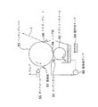
図9と図10に基づき、従来の塗工装置の概要を説明する。図9は塗工装置の従来例の模式的な側面図であり、特開2002−263549公報(特許文献1)に示される例であって、互いに圧接してニップ部を形成する2本のアプリケータロールを備え、ニップ部を通過するウエブの両面に2本のアプリケータロール上の塗工液膜を転写する塗工装置である。図10は、塗工装置の他の従来例の模式的な側面図である。 Based on FIG. 9 and FIG. 10, the outline | summary of the conventional coating apparatus is demonstrated. FIG. 9 is a schematic side view of a conventional example of a coating apparatus, which is an example shown in Japanese Patent Application Laid-Open No. 2002-263549 (Patent Document 1), in which two applications that press against each other to form a nip portion are shown. This is a coating apparatus that includes a roll and transfers a coating liquid film on two applicator rolls to both surfaces of a web that passes through a nip portion. FIG. 10 is a schematic side view of another conventional example of a coating apparatus.
図9において、前工程から搬送されてくる紙等のウエブ1は、対向した下部アプリケータロール2aと上部アプリケータロール2bが互いに圧接するニップ部4を通過して塗工液を塗布され、その後、ウエブ1を空気で浮上させた状態で搬送するターンバー(空気浮上式の非接触ターンバー)6を経由して乾燥器40に進入するようになっている。各アプリケータロール2a、2bは、鋼等の金属製のロール本体21a、21bの外周表面にゴム等の弾性皮膜22a、22bが施されたもので、ウエブ1の走行速度と等しい周速度で回転する。各アプリケータロール2a、2bの回転方向においてニップ部4の上流側に、各弾性皮膜22a、22bの表面に向けて塗工液を供給する手段である下部コータヘッド3a、上部コータヘッド3bが装備されている。
In FIG. 9, the
塗工液供給手段としての各コータヘッド3a、3bには、図示しない塗工液供給流路,計量ロッド,ブレードなどの計量手段が配設されており、各コータヘッド3a、3bから各アプリケータロール2a、2bの表面に十分な塗工液を供給した後、各コータヘッド3a、3b出口において図示しない計量ロッドをアプリケータロール2表面に押し付けて、各アプリケータロール2a、2b表面上に所定の膜厚の塗工液膜を形成するようにしている。
The
各アプリケータロール2a、2b上に形成された塗工液膜は、下部アプリケータロール2aと上部アプリケータロール2bが圧接したニップ部4において通過するウエブ1表面上に接触し転写、塗布される。塗工液を塗布されたウエブ1はターンバー6を介して乾燥器40に送られるが、ターンバー6は空気力でウエブ1を装置表面から浮上させた状態とすることでウエブ1表面を支持部材と接触させることなく支持し、ウエブ1表面に形成された未乾燥状態の塗工面品質を損なうこと無く、ウエブ1を乾燥器40に搬送することができる。
The coating liquid film formed on each
一方、ウエブ1に塗工液が転写・塗布されると、紙等の吸水性を有するウエブ1の場合は、この吸水によってウエブ1に伸縮が生じる。
On the other hand, when the coating liquid is transferred and applied to the
そのため、図9中に破線で示すようにウエブ1をニップ部4における接線方向に両アプリケータロール2a、2b間を直線的に通過させた場合は、ニップ部4を通過したウエブ1は、ターンバー6までの間においてその通過経路を特に規制されるような装置等を有していないため、ウエブ1に伸縮が生じ、特にニップ出側においてウエブ1が伸びて塗工液の粘着作用によって上部、下部いずれかのアプリケータロール2a、2bの表面に粘着して走行する状態が生じることがある。ウエブ1の幅(アプリケータロール2a、2bの軸方向幅)が広い場合には、この粘着状態がウエブ1幅方向に不均一となり、振動状態が発生し、高速で塗工を行う場合などには、この不均一な粘着状態が時間的に変動を始め、不安定な状態となることもある。
Therefore, when the
その結果、「剥がれパターン」といわれる塗工ムラが生じる他、塗工液が滴状となって飛散する「ミスティング」現象が発生する恐れがある。この現象が発生すると、塗工装置および塗工紙が汚損し、操業上支障をきたす可能性が生じる。また、ウエブ1と各アプリケータロール2a、2bとの接触距離がニップ部4のみ(約20mm程度)で短いため、塗工液のウエブ1に対する吸着、浸透が不十分な場合があり、塗工状態の不良、ミストの発生原因ともなった。
As a result, coating unevenness called a “peeling pattern” occurs, and a “misting” phenomenon in which the coating liquid scatters in the form of droplets may occur. When this phenomenon occurs, there is a possibility that the coating apparatus and the coated paper will be fouled and hinder the operation. Further, since the contact distance between the
そこで、図9に示された塗工装置では、ニップ部4通過後のウエブ1を上部アプリケータロール2bの表面に抱かせた状態で移送させるように空気浮上式のロール側ターンバー5がニップ部4下流側に設けられ、さらに、ニップ部4よりもウエブ1の走行方向上流側に、ニップ部4通過前のウエブ1を、上部アプリケータロール2bとは反対側の下部アプリケータロール2aの表面に抱かせた状態で移送させるようにペーパーロール7が設けられている。なお、ロール側ターンバー5は、ターンバー6と同様に空気力でウエブ1を装置表面から浮上させた状態とすることでウエブ1表面を支持部材と接触させることなく支持し、ウエブ1表面に形成された未乾燥状態の塗工面品質を損なうこと無く、ウエブ1を搬送することができる。
Therefore, in the coating apparatus shown in FIG. 9, the air-floating roll-
すなわち、ニップ部4通過後のウエブ1が空気浮上式のロール側ターンバー5によって一方の側の上部アプリケータロール2bの表面に抱かれるように移送されて後、上部アプリケータロール2bから剥離するので、剥離角度βが大きくなり剥離動作と剥離位置が安定するようになって、例えば「剥がれパターン」等の塗工ムラの発生や「ミスティング」現象を防止する。また、ウエブ1と上部アプリケータロール2bとの接触距離がニップ部4のみの場合より延長されるので、塗工液のウエブ1への浸透が促進され塗工状態が良好になる。
That is, since the
一方、ペーパーロール7により、ニップ部4通過前のウエブ1を、他方の側となる反対側の下部アプリケータロール2aの表面に抱かせた状態で移送させるようにして、ウエブ1と下部アプリケータロール2aとの接触距離がニップ部4のみの場合より延長されるので、下部アプリケータロール2aからウエブ1への塗工液の浸透が促進され塗工状態が良好になり、ニップ部4出口での「ミスティング」も減少する。
On the other hand, the
また、ニップ部4の上流側、下流側でそれぞれウエブ1の下面、上面がともに各アプリケータロール2a、2bと略同距離接触するように設定できるので両面の塗工状態を等しくすることが容易となる、というものである
しかしながら、近年、塗工装置はますます高速化の要請が高く(例えばウエブ速度:2000m/min以上)、上記のような従来の改良された塗工装置においても、高速で塗工する場合は、ウエブ1の同伴空気流と、ニップ部4の上流側でウエブ1に接触する下部アプリケータロール2aの同伴空気流が、ウエブ1と下部アプリケータロール2aの間に入り込み、ニップ部4入口側では、ウエブ1が浮上した状態となり下部アプリケータロール2a上の塗工液との接触が阻害される。そして、ウエブ1がニップ部4で初めて塗工液と接触する現象が生じ、ニップ部4上流側でウエブ1を下部アプリケータロール2aに巻き付けている効果が無くなるという問題があった。また、ニップ部4上流側での巻き付け効果が少なくなると、下部アプリケータロール2aでのウエブ1下面の塗工状態が悪くなるため、ウエブ1の両面の塗工状態に差異が生じる問題もあった。なお、これらの問題は、図9の配置を上下を反転した配置のものにおいても同様に生じる。
In addition, since the lower surface and upper surface of the
上記の従来例は互いに圧接してニップ部4を形成する2本のアプリケータロールを備え、ニップ部4を通過するウエブ1の両面に2本のアプリケータロール上の塗工液膜を転写,塗布する塗工装置であるが、特開平8−144196号公報(特許文献2)に示されるようなアプリケータロールとバッキングロールとの間のニップ部でウエブ1の片面に塗工を行う塗工装置においても同様な問題がある。
The above conventional example includes two applicator rolls that are pressed against each other to form the nip portion 4, and the coating liquid film on the two applicator rolls is transferred to both surfaces of the
図10は、そのような塗工装置の例であり、塗工液供給手段であるカーテンダイ51により塗布液をカーテン状に落下させて回転するアプリケータロール52周面上に供給し、均一な塗布液層を形成させ、次いでその塗布液層をバッキングロール53に巻回しつつ走行するウエブ1にニップ部54において転移させ、余剰に転移させた塗布液をドクタープレート56によって掻き落とすカーテン塗布法を行う。ウエブ1はニップ部54上流側のガイドロール55によりバッキングロール53に巻き付けられ、遮風板57を介してニップ部54に至る。塗布液は塗布液タンク59から塗布液ポンプ58によりカーテンダイ51に送られ、ニップ部54上流側のアプリケータロール52上に供給され、ニップ部54でウエブ1に転写される。
FIG. 10 shows an example of such a coating apparatus, in which a coating liquid is dropped onto a rotating applicator roll 52 around a rotating surface by a curtain die 51 which is a coating liquid supply means, and is uniformly distributed. A curtain coating method in which a coating liquid layer is formed, and then the coating liquid layer is transferred to the
そのため、アプリケータロール52周面上の同伴空気流がニップ部54に送り込まれ、また、遮風板57の作用はあるとしてもウエブ1上の同伴空気流も避け難くニップ部54に送り込まれるので、ウエブ上の塗布状態に悪影響を与える恐れが生じる。したがって、ウエブの片面に塗工を行う塗工装置においても、ウエブの同伴空気流とアプリケータロールの同伴空気流を除くことが求められる。
For this reason, the entrained air flow on the peripheral surface of the applicator roll 52 is sent to the nip portion 54, and even if the wind shield plate 57 acts, the accompanying air flow on the
しかしながら、ウエブの同伴空気流のみならずアプリケータロールの同伴空気流を共に除く有効な塗工装置の改良は十分なものが未だ示されておらず、例えば上記特許文献1の更なる改良を示すと思われる特開2003−326210公報(特許文献3)は、空気浮上式のロール側ターンバー5の改良に係るものである。
However, the improvement of an effective coating apparatus that excludes not only the air flow of the web but also the air flow of the applicator roll has not yet been shown sufficiently, for example, shows a further improvement of
本発明は、上記のような従来装置の問題を解決し、ウエブとアプリケータロールの同伴空気流を共に除き、ミストと塗工むらの発生を抑えて、均一な塗工液膜の形成や表裏の塗工状態の均一化を実現できる塗工装置を提供することを課題とするものである。 The present invention solves the problems of the conventional apparatus as described above, removes the air flow of the web and applicator roll together, suppresses the occurrence of mist and coating unevenness, and forms a uniform coating liquid film or both sides. It is an object of the present invention to provide a coating apparatus capable of realizing the uniform coating state.
本発明は、上記の課題を解決するためになされ、下記の(1)から(14)の手段を提供するものであり、以下、特許請求の範囲に記載の順に説明する。 The present invention has been made to solve the above problems, and provides the following means (1) to (14), and will be described below in the order of the claims.
(1)その第1の手段として、他のロールと互いに圧接してニップ部を形成するアプリケータロールを備え、同ニップ部を通過するウエブ表面上に同アプリケータロール上の塗工液を転写、塗布する塗工装置において、
同アプリケータロールの回転方向における前記ニップ部の上流側に設けられ同アプリケータロールの表面に向けて塗工液を供給する塗工液供給手段と、
前記ニップ部の上流側で同ニップ部と前記塗工液供給手段との間に設けられ、同ニップ部への空気の流入を防止する空気流入防止手段とを具備し、
同空気流入防止手段は、
前記アプリケータロールの表面へ同アプリケータロールの回転方向と反対方向に向かってエゼクタ気体を噴射するエゼクタを有してなることを特徴とする塗工装置を提供する。
(1) As the first means, an applicator roll that forms a nip portion by pressing with another roll is provided, and the coating liquid on the applicator roll is transferred onto the web surface passing through the nip portion. In the coating device to apply,
A coating liquid supply means for supplying a coating liquid toward the surface of the applicator roll provided on the upstream side of the nip portion in the rotation direction of the applicator roll;
An air inflow prevention means provided between the nip portion and the coating liquid supply means on the upstream side of the nip portion to prevent the inflow of air into the nip portion;
The air inflow prevention means
There is provided a coating apparatus comprising an ejector that ejects ejector gas onto the surface of the applicator roll in a direction opposite to the rotation direction of the applicator roll.
(2)第2の手段としては、第1の手段の塗工装置において、前記エゼクタ気体が蒸気であることを特徴とする塗工装置。 (2) The second means is a coating apparatus according to the first means, wherein the ejector gas is steam.
(3)また、第3の手段として、第1の手段または第2の手段の塗工装置において、前記エゼクタのノズルの噴射方向が、前記アプリケータロールの接線方向に対して10ないし45°を向くことを特徴とする塗工装置。 (3) As a third means, in the coating device of the first means or the second means, the ejecting direction of the nozzle of the ejector is 10 to 45 ° with respect to the tangential direction of the applicator roll. A coating device characterized by facing.
(4)第4の手段として、第1の手段ないし第3の手段のいずれかの塗工装置において、
前記空気流入防止手段は、
前記ウエブの走行方向において前記ニップ部より上流側で前記ウエブの前記アプリケータロールに接する側の面に同ウエブ幅方向で接して設けられるブレードを有してなることを特徴とする塗工装置を提供する。
(4) As a fourth means, in the coating apparatus of any one of the first means to the third means,
The air inflow prevention means includes
A coating apparatus comprising a blade provided in contact with the surface of the web in contact with the applicator roll on the upstream side of the nip portion in the running direction of the web in the web width direction. provide.
(5)第5の手段として、第4の手段の塗工装置において、
前記空気流入防止手段は、
前記エゼクタと前記ブレードとの間を塞ぐボックス正面板を有し、
前記アプリケータロールの回転方向における前記ニップ部の上流側で同ニップ部と前記エゼクタとの間に、
同ブレードと接する位置から前記アプリケータロールと接する位置までのウエブが形成する天板部と前記ボックス正面板と前記ブレードとが、前記ウエブの塗工される幅より広い幅を有して前記アプリケータロールの軸方向に沿って同アプリケータロールの円周面の一部を覆うように配置されたボックス部を形成し、
前記ボックス正面板および前記エゼクタは、塗工液を塗布された前記アプリケータロールと接触しない程度の間隔で近接して設置されてなることを特徴とする塗工装置を提供する。
(5) As a fifth means, in the coating device of the fourth means,
The air inflow prevention means includes
A box front plate that closes between the ejector and the blade;
Between the nip portion and the ejector on the upstream side of the nip portion in the rotation direction of the applicator roll,
The top plate portion formed by the web from the position in contact with the blade to the position in contact with the applicator roll, the box front plate, and the blade have a width wider than the width to which the web is applied. Forming a box portion arranged to cover a part of the circumferential surface of the applicator roll along the axial direction of the talol,
The box front plate and the ejector are provided close to each other at an interval that does not contact the applicator roll coated with a coating liquid.
(6)第6の手段として、第4の手段の塗工装置において、
前記空気流入防止手段は、
前記エゼクタと前記ブレードとの間を塞ぐボックス正面板と、ボックス正面板の下流側に同ボックス正面板と接続して前記ウエブと前記アプリケータロールとの接触点に向かって延設されたボックス天板とを有し、
前記アプリケータロールの回転方向における前記ニップ部の上流側で同ニップ部と前記エゼクタとの間に、
前記ボックス天板と前記ボックス正面板とが、前記ウエブの塗工される幅より広い幅を有して前記アプリケータロールの軸方向に沿って同アプリケータロールの円周面の一部を覆うように配置されたボックス部を形成し、
前記ボックス正面板および前記エゼクタは、塗工液を塗布された前記アプリケータロールと接触しない程度の間隔で近接して設置されてなることを特徴とする塗工装置を提供する。
(6) As a sixth means, in the coating device of the fourth means,
The air inflow prevention means includes
A box front plate that blocks between the ejector and the blade; and a box ceiling that is connected to the box front plate on the downstream side of the box front plate and extends toward a contact point between the web and the applicator roll. A board,
Between the nip portion and the ejector on the upstream side of the nip portion in the rotation direction of the applicator roll,
The box top plate and the box front plate cover a part of the circumferential surface of the applicator roll along the axial direction of the applicator roll having a width wider than the width to which the web is applied. Form a box part arranged as
The box front plate and the ejector are provided close to each other at an interval that does not contact the applicator roll coated with a coating liquid.
(7)第7の手段として、第4の手段の塗工装置において、
第1のエゼクタとしての前記エゼクタと、
前記ブレードに代えて、前記ウエブの走行方向におけるニップ部の上流側に設けられ、前記ウエブの前記アプリケータロールに接する側の面へ上流方向にエゼクタ気体を噴射する第2のエゼクタとを有してなることを特徴とする塗工装置。
(7) As a seventh means, in the coating device of the fourth means,
The ejector as a first ejector;
In place of the blade, a second ejector is provided on the upstream side of the nip portion in the running direction of the web, and ejects ejector gas in the upstream direction to the surface of the web in contact with the applicator roll. The coating apparatus characterized by comprising.
(8)第8の手段として、第7の手段の塗工装置において、
前記第2のエゼクタのノズルの噴射方向が、前記ウエブの表面に対して10ないし45°を向くことを特徴とする塗工装置を提供する。
(8) As an eighth means, in the coating device of the seventh means,
The coating apparatus is characterized in that the nozzle ejecting direction of the second ejector is 10 to 45 ° with respect to the surface of the web.
(9)第9の手段として、第7の手段または第8の手段の塗工装置において、
前記第1のエゼクタと第2のエゼクタとの間が塞がれて正面板部を形成し、
前記アプリケータロールの回転方向における前記ニップ部の上流側で同ニップ部と前記エゼクタとの間に、
前記第2のエゼクタに面する位置から前記アプリケータロールと接する位置までのウエブが形成する天板部と前記正面板部とが、前記ウエブの塗工される幅より広い幅を有して前記アプリケータロールの軸方向に沿って同アプリケータロールの円周面の一部を覆うように配置されたボックス部を形成し、
前記正面板部および前記第1のエゼクタは、塗工液を塗布された前記アプリケータロールと接触しない程度の間隔で近接して設置され、
前記第2のエゼクタは前記ウエブと接触しない程度の間隔で近接して設置されてなることを特徴とする塗工装置を提供する。
(9) As a ninth means, in the coating device of the seventh means or the eighth means,
Between the first ejector and the second ejector is closed to form a front plate part,
Between the nip portion and the ejector on the upstream side of the nip portion in the rotation direction of the applicator roll,
The top plate portion formed by the web from the position facing the second ejector to the position in contact with the applicator roll and the front plate portion have a width wider than the width to which the web is applied. Forming a box portion arranged so as to cover a part of the circumferential surface of the applicator roll along the axial direction of the applicator roll;
The front plate portion and the first ejector are installed close to each other so as not to come into contact with the applicator roll coated with a coating liquid,
The second ejector is provided close to the web so as not to come into contact with the web.
(10)第10の手段として、第5の手段、第6の手段または第9の手段の塗工装置において、
前記空気流入防止手段は、
前記ボックス部の前記アプリケータロール軸方向の両端部にそれぞれボックス端板を備え、
同ボックス端板は、塗工液を塗布された前記アプリケータロールと接触しない程度の間隔で近接して設置されてなることを特徴とする塗工装置を提供する。
(10) As a tenth means, in the coating device of the fifth means, sixth means or ninth means,
The air inflow prevention means includes
A box end plate is provided at each end of the box portion in the applicator roll axial direction,
The box end plate is provided close to the applicator roll coated with a coating solution at an interval that does not come into contact with the applicator roll.
(11)第11の手段として、第10の手段の塗工装置において、
前記ボックス端板は、
前記アプリケータロール軸方向に移動可能に設けられてなることを特徴とする塗工装置を提供する。
(11) As the eleventh means, in the coating device of the tenth means,
The box end plate is
Provided is a coating apparatus which is provided so as to be movable in the axial direction of the applicator roll.
(12)第12の手段として、第10の手段または第11の手段の塗工装置において、
前記空気流入防止手段は、
前記ボックス部に設けられた通気口を有し、
同通気口は同ボックス部内の気体を吸引する吸引装置に接続されてなることを特徴とする塗工装置を提供する。
(12) As a twelfth means, in the coating device of the tenth means or the eleventh means,
The air inflow prevention means includes
Having a vent provided in the box part;
The air vent is connected to a suction device that sucks the gas in the box portion, and provides a coating apparatus.
(13)第13の手段として、第10の手段または第11手段の塗工装置において、
前記空気流入防止手段は、
前記ボックス部に設けられた通気口を有し、
同通気口は同ボックス部内へ蒸気を供給する蒸気供給装置に接続されてなることを特徴とする塗工装置を提供する。
(13) As a thirteenth means, in the coating device of the tenth means or the eleventh means,
The air inflow prevention means includes
Having a vent provided in the box part;
The air vent is connected to a steam supply device for supplying steam into the box portion, and provides a coating apparatus.
(14)第14の手段として、
互いに圧接してニップ部を形成する2本のアプリケータロールを備え、同ニップ部を通過するウエブ表面上に同2本のアプリケータロール上の塗工液を転写、塗布する塗工装置において、
同ニップ部通過後の同ウエブを同2本のアプリケータロールのうち一方のアプリケータロールの表面に抱かせた状態で同ウエブを移送させる空気浮上式ターンバーが同ニップ下流側に設けられ、
同ニップ部よりも同ウエブの走行方向上流側に、同ニップ部通過前の同ウエブを前記一方のアプリケータロールとは反対側の他方のアプリケータロールの表面に抱かせた状態で同ウエブを移送させるペーパーロールが設けられ、
同ウエブと前記他方のアプリケータロールの表面との接触部よりも同ウエブの走行方向上流側であって同ウエブと前記他方のアプリケータロールの表面との間に前記ニップ部への空気の流入を防止する空気流入防止手段を具備してなることを特徴とする塗工装置を提供する。
(14) As the fourteenth means,
In a coating apparatus that includes two applicator rolls that press against each other to form a nip portion, and transfers and applies the coating liquid on the two applicator rolls onto the web surface that passes through the nip portion.
An air-floating turn bar is provided on the downstream side of the nip to transfer the web in a state where the web after passing through the nip is held on the surface of one of the two applicator rolls.
In the state where the web before passing the nip portion is held on the surface of the other applicator roll opposite to the one applicator roll, on the upstream side of the nip portion in the running direction of the web. A paper roll to be transported is provided,
Inflow of air into the nip portion between the web and the surface of the other applicator roll, which is upstream of the contact portion between the web and the surface of the other applicator roll in the running direction of the web. There is provided a coating apparatus characterized by comprising an air inflow prevention means for preventing the above.
本発明は上記の第1の手段から第14の手段の塗工装置を採用して、以下の作用効果を奏する。 The present invention employs the coating devices of the first to fourteenth means and has the following effects.
(1)特許請求の範囲に記載の請求項1の発明によれば、塗工装置を、他のロールと互いに圧接してニップ部を形成するアプリケータロールを備え、同ニップ部を通過するウエブ表面上に同アプリケータロール上の塗工液を転写、塗布する塗工装置において、同アプリケータロールの回転方向における前記ニップ部の上流側に設けられ同アプリケータロールの表面に向けて塗工液を供給する塗工液供給手段と、前記ニップ部の上流側で同ニップ部と前記塗工液供給手段との間に設けられ、同ニップ部への空気の流入を防止する空気流入防止手段とを具備し、同空気流入防止手段は、前記アプリケータロールの表面へ同アプリケータロールの回転方向と反対方向に向かってエゼクタ気体を噴射するエゼクタを有してなるように構成したので、アプリケータロールの回転に伴う同伴空気流は、エゼクタから噴射されるエゼクタ気体によって阻止され、ウエブとアプリケータロールの間に巻き込まれることが防止されるため、塗工液とウエブとの接触が阻害されず、ウエブのアプリケータロールに対する吸着性も向上し、塗工むらやミスティングが減少してウエブの塗工状態が向上する。
(1) According to the invention of
(2)請求項2の発明によれば、請求項1に記載の塗工装置において、前記エゼクタ気体が蒸気であるように構成したので、請求項1の発明の作用効果に加え、エゼクタ気体として蒸気を用いた場合、紙工プラント等では蒸気の供給源が豊富で利便性が高く、アプリケータロール上の塗工液の乾燥を防止し、加湿によるウエブの吸着性向上等の効果がある。
(2) According to the invention of claim 2, in the coating apparatus according to
(3)請求項3の発明によれば、請求項1または請求項2に記載の塗工装置において、
前記エゼクタのノズルの噴射方向が、前記アプリケータロールの接線方向に対して10ないし45°を向くように構成したので、請求項1または請求項2の発明の作用効果に加え、その角度範囲においてエゼクタ気体がアプリケータロールの同伴空気流に衝突することにより、同伴空気流を効果的に阻止することができる。
(3) According to the invention of claim 3, in the coating apparatus of
Since the ejecting direction of the nozzle of the ejector is configured to face 10 to 45 ° with respect to the tangential direction of the applicator roll, in addition to the operational effects of the invention of
(4)請求項4の発明によれば、請求項1ないし請求項3のいずれかに記載の塗工装置において、前記空気流入防止手段は、前記ウエブの走行方向において前記ニップ部より上流側で前記ウエブの前記アプリケータロールに接する側の面に同ウエブ幅方向で接して設けられるブレードを有してなるように構成したので、請求項1ないし請求項3のいずれかの発明の作用効果に加え、アプリケータロールの回転に伴う同伴空気流のみならず、ウエブの搬送に伴う同伴空気流が、ブレードにより阻止され、ウエブとアプリケータロールの間に巻き込まれることが防止されるため、塗工液とウエブとの接触が阻害されず、さらにウエブのアプリケータロールに対する吸着性も向上し、塗工むらやミスティングが減少してウエブの塗工状態がより向上する。
(4) According to a fourth aspect of the present invention, in the coating apparatus according to any one of the first to third aspects, the air inflow prevention means is upstream of the nip portion in the running direction of the web. Since the blade is provided so as to be in contact with the surface of the web in contact with the applicator roll in the width direction of the web, the effect of the invention according to any one of
(5)請求項5の発明によれば、請求項4に記載の塗工装置において、前記空気流入防止手段は、前記エゼクタと前記ブレードとの間を塞ぐボックス正面板を有し、前記アプリケータロールの回転方向における前記ニップ部の上流側で同ニップ部と前記エゼクタとの間に、同ブレードと接する位置から前記アプリケータロールと接する位置までのウエブが形成する天板部と前記ボックス正面板と前記ブレードとが、前記ウエブの塗工される幅より広い幅を有して前記アプリケータロールの軸方向に沿って同アプリケータロールの円周面の一部を覆うように配置されたボックス部を形成し、前記ボックス正面板および前記エゼクタは、塗工液を塗布された前記アプリケータロールと接触しない程度の間隔で近接して設置されてなるように構成したので、請求項4の発明の作用効果に加え、ニップ部の上流側のウエブのアプリケータロールの接する側の面がボックス部内に面し、外部に面しないので、ウエブとアプリケータロール間に同伴空気流が巻き込まれることがより効果的に防止される。また、エゼクタからのエゼクタ気体の噴射の背面側には負圧が発生するが、ボックス部内の負圧はウエブのアプリケータロールへの吸着を促進する一方、ボックス正面板またはエゼクタの下縁を、塗工液を塗布された下部アプリケータロールに接触しない程度に間隔をあけて近接して設置することで、負圧による空気の流入を減じることができ流入空気による同伴空気流の再発生を防ぐことができる。 (5) According to a fifth aspect of the present invention, in the coating apparatus according to the fourth aspect, the air inflow prevention means has a box front plate that closes between the ejector and the blade, and the applicator A top plate portion and a box front plate formed by a web from a position in contact with the blade to a position in contact with the applicator roll between the nip portion and the ejector on the upstream side of the nip portion in the rotation direction of the roll And the blade has a width wider than the width to which the web is applied, and is arranged so as to cover a part of the circumferential surface of the applicator roll along the axial direction of the applicator roll And the box front plate and the ejector are arranged close to each other so as not to come into contact with the applicator roll coated with a coating liquid. Therefore, in addition to the function and effect of the invention of claim 4, the surface on the upstream side of the nip where the applicator roll comes into contact faces the inside of the box and does not face the outside. It is more effectively prevented that the air flow is involved. In addition, negative pressure is generated on the back side of the ejector gas injection from the ejector, but the negative pressure in the box part promotes the adsorption of the web to the applicator roll, while the box front plate or the lower edge of the ejector is By installing it close enough to avoid contact with the lower applicator roll coated with the coating liquid, it is possible to reduce the inflow of air due to negative pressure and prevent reoccurrence of entrained air flow due to inflow air be able to.
(6)請求項6の発明によれば、請求項4に記載の塗工装置において、前記空気流入防止手段は、前記エゼクタと前記ブレードとの間を塞ぐボックス正面板と、ボックス正面板の下流側に同ボックス正面板と接続して前記ウエブと前記アプリケータロールとの接触点に向かって延設されたボックス天板とを有し、前記アプリケータロールの回転方向における前記ニップ部の上流側で同ニップ部と前記エゼクタとの間に、前記ボックス天板と前記ボックス正面板とが、前記ウエブの塗工される幅より広い幅を有して前記アプリケータロールの軸方向に沿って同アプリケータロールの円周面の一部を覆うように配置されたボックス部を形成し、前記ボックス正面板および前記エゼクタは、塗工液を塗布された前記アプリケータロールと接触しない程度の間隔で近接して設置されてなるように構成したので、請求項4の発明の作用効果に加え、エゼクタからのエゼクタ気体の噴射の背面側には負圧が発生するが、ボックス正面板またはエゼクタ、ボックス天板の下縁を、塗工液を塗布された下部アプリケータロールに接触しない程度に間隔をあけて近接して設置することで、空気の流入を減じることができ流入空気による同伴空気流の再発生を防ぐ効果を高めることができる。また、ボックス部の一部をウエブ自体で構成した場合は、薄いウエブや密度の低いウエブにおいて空気がウエブ表面を貫通しボックス部の内部へ流入しボックス部を構成した効果が低下する恐れがあるが、ウエブとは別にボックス天板を備えてボックス部を構成するので、その恐れは無い。 (6) According to the invention of claim 6, in the coating apparatus according to claim 4, the air inflow prevention means includes a box front plate that blocks between the ejector and the blade, and a downstream of the box front plate. A box top plate connected to the front plate of the box and extending toward a contact point between the web and the applicator roll, and upstream of the nip portion in the rotation direction of the applicator roll The box top plate and the box front plate have a width wider than the width of the web to be applied between the nip portion and the ejector along the axial direction of the applicator roll. A box part is formed so as to cover a part of the circumferential surface of the applicator roll, and the box front plate and the ejector do not come into contact with the applicator roll coated with a coating liquid. In addition to the function and effect of the invention of claim 4, a negative pressure is generated on the back side of the ejector gas injection from the ejector. Or, by placing the lower edge of the ejector and box top plate close to each other so as not to contact the lower applicator roll coated with the coating solution, the inflow of air can be reduced. The effect of preventing the reoccurrence of the accompanying air flow can be enhanced. In addition, when a part of the box portion is formed of the web itself, there is a possibility that the effect of the box portion being reduced by air flowing through the surface of the web and flowing into the box portion in a thin web or a low density web. However, since the box part is configured by providing the box top plate separately from the web, there is no fear of that.
(7)請求項7の発明によれば、請求項4に記載の塗工装置において、第1のエゼクタとしての前記エゼクタと、前記ブレードに代えて、前記ウエブの走行方向におけるニップ部の上流側に設けられ、前記ウエブの前記アプリケータロールに接する側の面へ上流方向にエゼクタ気体を噴射する第2のエゼクタとを有してなるように構成したので、請求項4の発明の作用効果に加え、アプリケータロールの回転に伴う同伴空気流は、第1のエゼクタから噴射されるエゼクタ気体によって阻止され、ウエブの搬送に伴う同伴空気流は、第2のエゼクタから噴射されるエゼクタ気体によって阻止され、ウエブとアプリケータロールの間に巻き込まれることが防止されるため、塗工液とウエブとの接触が阻害されず、さらにウエブのアプリケータロールに対する吸着性も向上し、塗工むらやミスティングが減少してウエブの塗工状態がより向上する。また、ブレードに代えて、第2のエゼクタを設けたことにより、ウエブに非接触で同伴空気流阻止を行うことができ、ウエブの断紙の恐れがなくなる。
(7) According to the invention of
(8)請求項8の発明によれば、請求項7に記載の塗工装置において、前記第2のエゼクタのノズルの噴射方向が、前記ウエブの表面に対して10ないし45°を向くように構成したので、請求項7の発明の作用効果に加え、その角度範囲においてエゼクタ気体がウエブの同伴空気流に衝突することにより、同伴空気流を効果的に阻止することができる。
(8) According to the invention of claim 8, in the coating apparatus according to
(9)請求項9の発明によれば、請求項7または請求項8に記載の塗工装置において、前記第1のエゼクタと第2のエゼクタとの間が塞がれて正面板部を形成し、前記アプリケータロールの回転方向における前記ニップ部の上流側で同ニップ部と前記エゼクタとの間に、前記第2のエゼクタに面する位置から前記アプリケータロールと接する位置までのウエブが形成する天板部と前記正面板部とが、前記ウエブの塗工される幅より広い幅を有して前記アプリケータロールの軸方向に沿って同アプリケータロールの円周面の一部を覆うように配置されたボックス部を形成し、前記正面板部および前記第1のエゼクタは、塗工液を塗布された前記アプリケータロールと接触しない程度の間隔で近接して設置され、前記第2のエゼクタは前記ウエブと接触しない程度の間隔で近接して設置されてなるように構成したので、請求項7または請求項8の発明の作用効果において、ニップ部の上流側のウエブのアプリケータロールと接する側の面がボックス内に面し、外部に面しないので、ウエブとアプリケータロール間に同伴空気流が巻き込まれることがより効果的に防止される。また、第1のエゼクタおよび第2のエゼクタからのエゼクタ気体の噴射の背面側には負圧が発生するが、ボックス部内の負圧はウエブのアプリケータロールへの接触を促進する一方、第1のエゼクタとボックス端板の下縁を、塗工液を塗布されたアプリケータロールに接触しない程度に間隔をあけて近接して設置し、第2のエゼクタはウエブと接触しない程度の間隔をあけて近接して設置することで、負圧による空気の流入を減じることができ流入空気による同伴空気流の再発生を防ぐことができる。
(9) According to the invention of
(10)請求項10の発明によれば、請求項5、請求項6または請求項9に記載の塗工装置において、前記空気流入防止手段は、前記ボックス部の前記アプリケータロール軸方向の両端部にそれぞれボックス端板を備え、同ボックス端板は、塗工液を塗布された前記アプリケータロールと接触しない程度の間隔で近接して設置されてなるように構成したので、請求項5、請求項6または請求項9の発明の作用効果において、ボックス部の左右側方が開放されていると、ボックス部の幅が十分でない場合は、左右からボックス内へ空気が流入し同伴空気流が再発生し、エゼクタの同伴空気流阻止の効果を減じる恐れがあるが、ボックス部の左右の端部の開口を塞ぐようにボックス端板を設け、アプリケータロールと接触しない程度の間隔で近接して設置することで、より効果的に空気の流入を減じることができ、流入空気による同伴空気流の再発生を防ぐことができる。
(10) According to the invention of
(11)請求項11の発明によれば、請求項10に記載の塗工装置において、前記ボックス端板は、前記アプリケータロール軸方向に移動可能に設けられてなるように構成したので、請求項10の発明の作用効果に加え、幅の狭いウエブの場合にウエブの幅に合わせてボックス端板を位置させることで、ウエブ側方からのボックス部内への空気の流入が防止でき、なかんずく、ウエブがボックス部の天板部を形成している場合は、特に効果を顕著に奏することができる。
(11) According to the invention of
(12)請求項12の発明によれば、請求項10または請求項11に記載の塗工装置において、前記空気流入防止手段は、前記ボックス部に設けられた通気口を有し、同通気口は同ボックス部内の気体を吸引する吸引装置に接続されてなるように構成したので、請求項10または請求項11の発明の作用効果に加え、ボックス部に流入した空気を排出することにより流入空気による同伴空気流の再発生がより効果的に防止され、ボックス部内の負圧を維持できるため、ウエブのアプリケータロールに対する吸着性が向上し、ニップ部通過後のミスト発生が著しく減少する。なかんずく、ウエブがボックス部の天板部を形成している場合は、特に効果を顕著に奏することができる。
(12) According to a twelfth aspect of the present invention, in the coating apparatus according to the tenth or eleventh aspect, the air inflow prevention means has a vent hole provided in the box portion. Since it is configured to be connected to a suction device for sucking the gas in the box portion, in addition to the operational effects of the invention of
(13)請求項13の発明によれば、請求項10または請求項11に記載の塗工装置において、前記空気流入防止手段は、前記ボックス部に設けられた通気口を有し、同通気口は同ボックス部内へ蒸気を供給する蒸気供給装置に接続されてなるように構成したので、請求項10または請求項11の発明の作用効果に加え、ボックス部内の空気の多くを蒸気に置換するとともに微正圧に設定することで、空気の流入を防止でき、蒸気の同伴流は発生してもアプリケータロールとウエブの表面の境界層では蒸気が凝縮により負圧を発生し、ウエブのアプリケータロールに対する吸着性が向上し、また、ウエブが蒸気の凝縮により濡れ性が上がり、塗工液被覆率が上がって塗工品質が向上する。なかんずく、ウエブがボックスの天板部を形成している場合は、特に効果を顕著に奏することができる。
(13) According to a thirteenth aspect of the present invention, in the coating apparatus according to the tenth or eleventh aspect, the air inflow prevention means has a vent hole provided in the box portion. Since it is configured to be connected to a steam supply device for supplying steam into the box portion, in addition to the operational effects of the invention of
(14)請求項14の発明によれば、塗工装置を、互いに圧接してニップ部を形成する2本のアプリケータロールを備え、同ニップ部を通過するウエブ表面上に同2本のアプリケータロール上の塗工液を転写、塗布する塗工装置において、同ニップ部通過後の同ウエブを同2本のアプリケータロールのうち一方のアプリケータロールの表面に抱かせた状態で同ウエブを移送させる空気浮上式ターンバーが同ニップ下流側に設けられ、同ニップ部よりも同ウエブの走行方向上流側に、同ニップ部通過前の同ウエブを前記一方のアプリケータロールとは反対側の他方のアプリケータロールの表面に抱かせた状態で同ウエブを移送させるペーパーロールが設けられ、同ウエブと前記他方のアプリケータロールの表面との接触部よりも同ウエブの走行方向上流側であって同ウエブと前記他方のアプリケータロールの表面との間に前記ニップ部への空気の流入を防止する空気流入防止手段を具備してなるように構成したので、互いに圧接してニップ部を形成する2本のアプリケータロールを備え、そのニップ部を通過するウェブの両面表面上に2本のアプリケータロール上の塗工液膜を転写、塗布する塗工装置において、空気流入防止手段がニップ部への空気の流入を防止するので、ニップ部の上流側でのウエブのアプリケータロールへの巻き付きにおいて、塗工液とウエブとの接触が阻害されず、ウエブのアプリケータロールに対する吸着性も向上し、塗工むらやミスティングが減少してウエブの塗工状態が向上するとともに、ニップ部の上流側、下流側の塗工状態を等しくすることが容易であるので、ウエブ両面の塗工状態が揃って品質向上が図られる。 (14) According to the fourteenth aspect of the present invention, the coating apparatus includes two applicator rolls that press-contact each other to form a nip portion, and the two application devices on the web surface passing through the nip portion. In a coating apparatus for transferring and coating the coating liquid on the talol, the web after passing through the nip portion is held on the surface of one of the two applicator rolls. An air floating turn bar is provided on the downstream side of the nip, upstream of the nip portion in the running direction of the web, and the web before passing the nip portion on the opposite side of the one applicator roll. A paper roll for transferring the web while being held on the surface of the other applicator roll is provided, and the web travels more than the contact portion between the web and the surface of the other applicator roll. Since the air flow preventing means for preventing the inflow of air into the nip portion is provided between the web and the surface of the other applicator roll on the improved flow side, they are pressed against each other. In a coating apparatus that includes two applicator rolls that form a nip portion, and transfers and coats a coating liquid film on the two applicator rolls on both surfaces of a web that passes through the nip portion, Since the inflow prevention means prevents the inflow of air into the nip portion, the contact between the coating liquid and the web is not hindered when the web is wound around the applicator roll on the upstream side of the nip portion. Adsorption to the roll is also improved, coating unevenness and misting are reduced, and the coating state of the web is improved, and the upstream and downstream coating states of the nip portion can be easily equalized. Since, quality uniform in coating state of the web both surfaces is achieved.
本発明を実施するための最良の形態として、以下に本発明の実施例1から実施例3を説明する。 Examples 1 to 3 of the present invention will be described below as the best mode for carrying out the present invention.
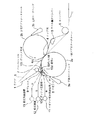
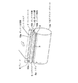
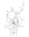
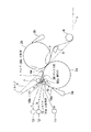
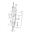
図1から図4に基づき、本発明の実施例1に係る塗工装置を以下説明する。図1は、本実施例の塗工装置の模式的な側面図であり、図2は本実施例のボックス部およびエゼクタの配置を示す斜視図、図3はエゼクタの断面図、図4はボックス部およびエゼクタの詳細斜視図である。本実施例は、前述の図9で示した従来例に対して、ニップ部4の上流側の構造に違いがある他は同様であり、同様部分には同符号を付し説明を省略ないし簡略とし、同従来例と異なる点を主に以下説明する。 A coating apparatus according to Example 1 of the present invention will be described below with reference to FIGS. FIG. 1 is a schematic side view of the coating apparatus of the present embodiment, FIG. 2 is a perspective view showing the arrangement of the box portion and the ejector of the present embodiment, FIG. 3 is a sectional view of the ejector, and FIG. It is a detailed perspective view of a part and an ejector. This embodiment is the same as the above-described conventional example shown in FIG. 9 except that there is a difference in the structure on the upstream side of the nip portion 4, and the same portions are denoted by the same reference numerals and description thereof is omitted or simplified. Differences from the conventional example will be mainly described below.
図1において、前工程から搬送されてくる紙等のウエブ1は、対向した下部アプリケータロール2a(本発明における「アプリケータロール」、または「他のアプリケータロール」:後述の他の実施例において同じ)と上部アプリケータロール2b(本発明における「他のロール」または「一方のアプリケータロール」:後述の他の実施例において同じ)が互いに圧接するニップ部4を通過して塗工液を塗布され、その後、ウエブ1を空気で浮上させた状態で搬送するターンバー6を経由して乾燥器40(図9参照)に進入する。各アプリケータロール2a、2bは、鋼等の金属製のロール本体の外周表面にゴム等の弾性皮膜が施されたもので、ウエブ1の走行速度と等しい周速度で回転する。また、各アプリケータロール2a、2bの回転方向においてニップ部4の上流側に、各アプリケータロール2a、2bの表面に向けて塗工液を供給する手段である下部コータヘッド3a、上部コータヘッド3bが装備されている。
In FIG. 1, a
塗工液供給手段としての各コータヘッド3a、3bは、各アプリケータロール2a、2b表面上に所定の膜厚の塗工液膜を形成し、各アプリケータロール2a、2b上に形成された塗工液膜は、ニップ部4において通過するウエブ1表面上に接触し転写、塗布される。塗工液を塗布されたウエブ1はターンバー6を介して乾燥器40に送られる。
Each
また、ニップ部4とターンバー6との間には、空気浮上式のロール側ターンバー5(本発明における「空気浮上式ターンバー」)が設けられ、図中破線で示すニップ部4の接線方向よりニップ部4通過後のウエブ1を上部アプリケータロール2bの表面側に寄せて、上部アプリケータロール2bの表面に抱かせた状態でウエブ1を移送させるようにしている。
Further, an air floating type roll side turn bar 5 (“air floating type turn bar” in the present invention) is provided between the nip portion 4 and the turn bar 6, and the nip from the tangential direction of the nip portion 4 indicated by a broken line in the figure. The
さらに、ニップ部4よりもウエブ1の走行方向上流側にはペーパーロール7が設けられ、ニップ部4通過前のウエブ1を、上部アプリケータロール2bとは反対側の下部アプリケータロール2aの表面側に寄せて、上部アプリケータロール2bの表面に抱かせた状態で同ウエブを移送させるようにしている。以上は、図9のものと同様である。
Further, a
本実施例においては、図1、図2に示すように、下部アプリケータロール2aの回転方向においてニップ部4の上流側でニップ部4と下部コータヘッド3aとの間に、下部アプリケータロール2aの略全幅にわたって(あるいは、少なくとも塗工するウエブ1を覆うように)、下部アプリケータロール2a表面へ上流方向にエゼクタ気体aを噴射するエゼクタ8が、本発明における「空気流入防止手段」の一つとして設けられている。
In this embodiment, as shown in FIGS. 1 and 2, the
エゼクタ8は、図3に示されるように、閉塞した筒状中空体に下部アプリケータロール2aの円周表面の回転方向における上流方向へ向けたノズル8aを設けたものである。ノズル8aの向き(噴射方向)の噴射角αは塗工液や下部アプリケータロール2a回転速度等によって設定されるが、エゼクタ気体aが吹き付けられる位置での下部アプリケータロール2aの接線方向に対して好ましくは10°ないし45°程度であり、その角度範囲において下部アプリケータロール2aの同伴空気流に衝突することにより、エゼクタ気体aが同伴空気流に跳ね上げられることも押し返されることも少なく、同伴空気流を効果的に阻止することができる。また、ノズル8aは、スリット状、多孔列等に形成される。
As shown in FIG. 3, the ejector 8 has a closed cylindrical hollow body provided with a
エゼクタ8の筒状中空体内には、図1に略図示するように、適宜のエゼクタ気体供給装置11からエゼクタ気体aが供給される。エゼクタ気体aは、空気が一般的に用い得るが、条件によって水蒸気(以下、単に「蒸気」という。特許請求の範囲の記載において同じ)、窒素等不活性ガスないしそれに準ずるガス等、適宜のガスを用いる。エゼクタ気体aの噴射速度は、適宜設定できるが、下部アプリケータロール2aの回転に伴う同伴空気流を阻止するためには、概ね下部アプリケータロール2aの回転周速度(すなわちウエブ速度)と同等の逆向き速度かそれ以上が好ましい。しかし、あまり速度が過剰になると下部アプリケータロール2a周面上の塗工液の状態を乱すことになり好ましくない。
As shown schematically in FIG. 1, the ejector gas a is supplied from an appropriate ejector
なお、ウエブ1側の同伴空気流を阻止するために、ウエブ1の走行方向においてニップ部4より上流側に、ブレード9が、ウエブ1の下部アプリケータロール2aに接する側の面にウエブ幅方向で接するように設けられる。
In order to prevent the entrained air flow on the
図1、図2に示すように、下部アプリケータロール2aの回転方向においてニップ部4の上流側でニップ部4と下部コータヘッド3aとの間に、上流側のボックス正面板10aと下流側のボックス天板10cが下部アプリケータロール2aの左右方向に断面山形のボックス部10を、本発明における「空気流入防止手段」の一つとして形成して、下部アプリケータロール2aの円周面表面の一部を覆うように設けられている。
As shown in FIGS. 1 and 2, the upstream box
ボックス部10は、下部アプリケータロール2aの略全幅にわたる(少なくとも塗工するウエブ1を覆う)幅を有し、ボックス正面板10aとボックス天板10cの合わさる頂部近傍には、ボックス部10の略全幅にわたる(あるいは、少なくとも塗工するウエブ1の幅以上の)ブレード9が、本発明における「空気流入防止手段」の1要素としてその一端縁が取付けられている。
The
ブレード9の他端縁はペーパーロール7上を巻き回されるウエブ1にウエブ幅方向で当接するように設定される。前述のエゼクタ8は、ボックス正面板10aに設けられている。なお、エゼクタ8はボックス正面板10aに一体化して形成しても、別体に形成して取付けてもよい。また、ボックス正面板10aとブレード9とは別部材構成として図示しているが、同一部材としても簡潔な構造で同様の効果を奏し、別部材構成とすればブレード磨耗時の取り替えが容易になるメリットがある。また、エゼクタ8とブレード9とを一体に形成してそれが実質的にボックス正面板10aを形成するものとしてもよい。
The other end edge of the
上記構成では、下部アプリケータロール2a側のエゼクタ8とウエブ1側のブレード9との間をボックス正面板10aで塞ぎ、ボックス正面板10a、ブレード9及びボックス天板10cによりボックス部10を構成することでニップ部4への同伴空気流の噛み込みを防止できる。
In the above configuration, the box
しかし、ボックス部10は内部に空気の流入が少ないほうが好ましく、ボックス部10の左右の端部(下部アプリケータロール2a軸方向の両端部)となるボックス天板10cの左右の端部には山形断面の開口を塞ぐようにボックス端板10bが設けられ、ボックス部の幅が十分でない場合は特に効果がある。また、ボックス天板10cの下縁は、ニップ部4上流側のウエブ1に接しない範囲で下流方向に(下部アプリケータロール2aとウエブ1が接する点4aに向けて)延在するように設定され、ボックス正面板10a(またはエゼクタ8)、ボックス端板10b、ボックス天板10cの下縁は、塗工液を塗布された下部アプリケータロール2aと接触しない程度の間隔をあけて近接して設置する。
However, it is preferable that the air flow into the
ボックス部10には、好ましくは、図4に示すような通気口10dが設けられ、通気口10dに接続する通気管を、図1に略図示するように、吸引装置12に接続しボックス部10内の気体(通常は空気)bを吸引するように構成し、また或いは、図1に略図示するように、蒸気供給装置13に接続しボックス部10内へ水蒸気(以下、単に「蒸気」という。特許請求の範囲の記載において同じ)cを供給するように構成する。通気口10dは、ボックス端板10b、ボックス正面板10a等に適宜設けられ、その位置は限定されないが、流入空気の排出箇所としては最も流入しやすいボックス部10両端でボックス端板10bに設けることが効果的である。
The
上記のように構成された本実施例の塗工装置においては、下部アプリケータロール2a
の回転に伴う同伴空気流は、エゼクタ8のノズル8aから噴射されるエゼクタ気体aによって阻止され、ウエブ1と下部アプリケータロール2aの間に巻き込まれることが防止される。また、ウエブ1の搬送に伴う同伴空気流は、ブレードにより阻止され、ウエブ1と下部アプリケータロール2aの間に巻き込まれることが防止される。
In the coating apparatus of the present embodiment configured as described above, the
The entrained air flow accompanying the rotation is blocked by the ejector gas a ejected from the
しかしながら、エゼクタ8からのエゼクタ気体aの噴射の背面側には負圧が発生するため、ボックス部10が周囲(特に左右側方)に対して開放されていると、周囲からボックス部10内へ空気が流入し同伴空気流を再発生し、エゼクタ8の同伴空気流阻止の効果を減じる恐れがある。特に、ボックス部の幅が小さい場合にその恐れが大きい。
However, since negative pressure is generated on the back side of the ejection of the ejector gas a from the ejector 8, if the
そこで、ボックス部10の左右の端部に山形断面の開口を塞ぐようにボックス端板10bを設け、ボックス正面板10aまたはエゼクタ8、ボックス端板10b、ボックス天板10cの下縁を、塗工液を塗布された下部アプリケータロール2aに接触しない程度に間隔をあけて近接して設置することで、空気の流入を減じることができ流入空気による同伴空気流の再発生を防ぐことができる。
Therefore, a
なお、ボックス端板10bを下部アプリケータロール2aの軸方向に移動可能とし、ウエブ1の幅に合わせて位置させるようにすれば、空気の流入を防止する上でさらに好ましい。また、後述の実施例2、実施例3等のようにボックス部の一部をウエブ1自体で構成した場合は、薄いウエブ1や密度の低いウエブ1において空気がウエブ表面を貫通しボックス部の内部へ流入しボックス部を構成した効果が低下する恐れがあるが、本実施例ではウエブ1自体でボックス部10を構成しないので、その恐れは無い。
It is more preferable to prevent the inflow of air if the
ここで、前述のように、ボックス部10に通気口10dを設け、通気口10dに接続する通気管を吸引装置12に接続しボックス部10内の気体(通常は空気)bを吸引するように構成すれば、ボックス部10に流入した空気を排出することにより流入空気による同伴空気流の再発生がより効果的に防止される。また、ボックス部10内の負圧を維持できるので、ボックス天板10cの下縁近傍で下部アプリケータロール2aと接するウエブ1の下部アプリケータロール2aに対する吸着性が向上する。その結果、ニップ部4通過後のミスト発生が著しく減少し、例えば、エゼクタ8噴射とボックス部10の気体吸引を行わなかった場合のミスト発生量が、約0.045g/m2 /secであったものが、エゼクタ8噴射とボックス部10の気体吸引を行って、約0.003〜0.009g/m2 /secと、約10分の1に減じた。
Here, as described above, the
または、通気口10dに接続する通気管を13に接続しボックス部10内へ蒸気cを供給するように構成すれば、ボックス部10内の空気の多くを蒸気cに置換するとともに微正圧に設定することで、空気の流入を防止でき、蒸気の同伴流は発生しても下部アプリケータロール2aとウエブ1の表面の境界層では蒸気が凝縮により負圧を発生し、ウエブ1の下部アプリケータロール2aに対する吸着性が向上する。
Alternatively, if a vent pipe connected to the
そして、ウエブ1が蒸気の凝縮により濡れ性が上がり(ウエブ表面、細孔内の空気層と凝縮水とが置換することによる)、塗工液被覆率が上がって塗工品質が向上する。
Then, the wettability of the
なお、エゼクタ8のエゼクタ気体aとしては、空気が一般的に適用できるが、蒸気を用いた場合、紙工プラント等では蒸気の供給源が豊富で利便性が高いことに加えて、下部アプリケータロール2a上の塗工液の乾燥を防止し、加湿によるウエブ1の吸着性向上等の効果がある。また、特殊な塗工液の場合には不活性ガスをエゼクタ気体aとして不測の反応を防止することもできる。
As the ejector gas a of the ejector 8, air is generally applicable. However, when steam is used, the lower applicator roll is used in addition to the fact that the supply source of steam is abundant and convenient in a papermaking plant or the like. The coating liquid on 2a is prevented from being dried, and there is an effect of improving the adsorptivity of the
以上のように本実施例では、ウエブ1の同伴空気流のみならず下部アプリケータロール2aの同伴空気流を共に除くことができるので塗工液とウエブ1との接触が阻害されず、ウエブ1の下部アプリケータロール2aに対する吸着性も向上し、塗工むらやミスティングが減少してウエブ1の塗工状態が向上する。
As described above, in this embodiment, not only the entrained air flow of the
また、以上のようにニップ部4の上流側の塗工状態が改善され、ニップ部4の上流側、下流側の塗工状態を等しくすることが容易であるので、ウエブ1両面の塗工状態が揃って品質向上が図られる。 Further, as described above, the coating state on the upstream side of the nip portion 4 is improved, and it is easy to make the coating state on the upstream side and downstream side of the nip portion 4 equal. As a result, quality can be improved.
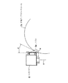
図5、図6に基づき、本発明の実施例2に係る塗工装置を以下説明する。図5は、本実施例の塗工装置の模式的な側面図であり、図6は本実施例のボックス部およびエゼクタの配置を示す斜視図である。本実施例においては、ボックス部の構成が異なる他は実施例1と同様であり、同様部分には同符号を付し説明を簡略とし、実施例1と異なる点を主に以下説明する。なお、エゼクタは図2に示すものと同様である。 A coating apparatus according to Embodiment 2 of the present invention will be described below based on FIGS. FIG. 5 is a schematic side view of the coating apparatus of the present embodiment, and FIG. 6 is a perspective view showing the arrangement of the box portion and the ejector of the present embodiment. The present embodiment is the same as the first embodiment except that the configuration of the box portion is different. The same parts are denoted by the same reference numerals to simplify the description, and differences from the first embodiment will be mainly described below. The ejector is the same as that shown in FIG.
本実施例においては、図5、図6に示すように、下部アプリケータロール2aの回転方向においてニップ部4の上流側でニップ部4と下部コータヘッド3aとの間に、下部アプリケータロール2aの略全幅にわたって(あるいは、少なくとも塗工するウエブ1を覆うように)、下部アプリケータロール2aの回転に伴う同伴空気流を阻止するために、下部アプリケータロール2a表面へ上流方向にエゼクタ気体aを噴射するエゼクタ8が本発明における「空気流入防止手段」の一つとして設けられている。エゼクタ8は、図3に示す実施例1同様であり、説明を省略する。
In this embodiment, as shown in FIGS. 5 and 6, the
なお、ウエブ1側の同伴空気流を阻止するために、ウエブ1の走行方向においてニップ部4より上流側に、ブレード9が本発明における「空気流入防止手段」の1要素として、ウエブ1の下部アプリケータロール2aに接する側の面にウエブ幅方向で接するように設けられる。
In order to prevent the entrained air flow on the
また、図5、図6に示すように、下部アプリケータロール2aの回転方向においてニップ部4の上流側でニップ部4と下部コータヘッド3aとの間に、ボックス正面板20aとその上縁近傍に取付けられたブレード9とが上流側の壁となり、ニップ部4上流側のウエブ1がブレード9と接する位置から下部アプリケータロール2aに接する位置4aまでを、前述の実施例1のボックス天板10cに代えて下流側の壁となる天板部20cとなり、下部アプリケータロール2aの左右方向に断面山形のボックス部20を、本発明における「空気流入防止手段」の一つとして形成して、下部アプリケータロール2aの円周面表面の一部を覆うように設けられている。
Further, as shown in FIGS. 5 and 6, the box
ボックス正面板20aは、下部アプリケータロール2aの略全幅にわたる(少なくとも塗工するウエブ1を覆う)幅を有し、ボックス正面板20aの上縁には、ボックス正面板20aの略全幅にわたるブレード9の一端縁が取付けられ、ブレード9の他端縁はペーパーロール7上を巻き回されるウエブ1にウエブ幅方向で当接するように設定される。前述のエゼクタ8は、ボックス正面板20aに設けられている。なお、エゼクタ8はボックス正面板20aに一体化して形成しても、別体に形成して取付けてもよい。また、ボックス正面板20aとブレード9とは別部材構成としても同一部材としてもよく、あるいはエゼクタ8とブレード9とを一体に形成してそれが実質的にボックス正面板20aを形成するものとしてもよいことは実施例1と同様である。
The box
上記構成では、下部アプリケータロール2a側のエゼクタ8とウエブ1側のブレード9との間をボックス正面板20aで塞ぎ、ボックス正面板20a、ブレード9及び天板部20cによりボックス部20を構成することでニップ部4への同伴空気流の噛み込みを防止できる。
In the above configuration, the box
ボックス部20は内部に空気の流入が少ないほうが好ましく、ボックス部20の左右の端部となるウエブ1による天板部20cの左右の端部には山形断面の開口を塞ぐようにボックス端板20bが設けられ、ボックス部20の幅が十分でない場合は特に効果がある。また、ボックス正面板20a(またはエゼクタ8)、ボックス端板20bの下縁は、塗工液を塗布された下部アプリケータロール2aと接触しない程度に間隔をあけて近接して設置すると好ましい。
It is preferable that the air flow into the box portion 20 is small, and the box end plate 20b is formed so that the left and right end portions of the top plate portion 20c formed by the
さらに、ボックス端板20bは下部アプリケータロール2aの軸方向(幅方向)に可動構造として、ウエブ1による天板部20cの幅に合わせた位置に位置調整の上設定できるようにするのが好ましく、その場合、天板部20cの左右に開口が生じず、ボックス部20内への空気の流入をより効果的に防止できる。
Further, it is preferable that the box end plate 20b is movable in the axial direction (width direction) of the
ボックス部20には、好ましくは通気口20dが設けられ、通気口20dに接続する通気管を、図5に略図示するように、吸引装置12に接続しボックス部20内の気体bを吸引するように構成し、またあるいは、図5に略図示するように、蒸気供給装置13に接続しボックス部20内へ蒸気cを供給するように構成する。通気口20dは、ボックス端板20bかボックス正面板20aかに適宜設けられ、その位置は限定されないが、流入空気の排出箇所としては最も流入しやすいボックス部20両端でボックス端板20bに設けることが効果的である。
The box portion 20 is preferably provided with a
上記のように構成された本実施例の塗工装置においては、下部アプリケータロール2a
の回転に伴う同伴空気流は、エゼクタ8のノズル8aから噴射されるエゼクタ気体aによって阻止され、ウエブ1の搬送に伴う同伴空気流は、ブレード9により阻止され、しかもニップ部4上流側のウエブ1と下部アプリケータロール2aの接する側の面がボックス部20内に面し、外部に面しないので、ウエブ1と下部アプリケータロール2a間に同伴空気流が巻き込まれることがより効果的に防止される。
In the coating apparatus of the present embodiment configured as described above, the
The entrained air flow accompanying the rotation of the ejector 8 is blocked by the ejector gas a ejected from the
しかしながら、エゼクタ8からのエゼクタ気体aの噴射の背面側には負圧が発生するため、ボックス部20内の負圧はウエブ1の下部アプリケータロール2aへの吸着を促進する効果がある一方、ボックス部20が周囲に対して開放されていると、周囲からボックス部20内へ空気が流入し同伴空気流を再発生し、エゼクタ8の同伴空気流阻止の効果を減じる恐れがある。
However, since a negative pressure is generated on the back side of the ejection of the ejector gas a from the ejector 8, the negative pressure in the box portion 20 has an effect of promoting the adsorption of the
そこで、ボックス部20の左右の端部の山形断面の開口を塞ぐようにボックス端板20bを設け、ボックス正面板20a(またはエゼクタ8)、ボックス端板20bの下縁を、塗工液を塗布された下部アプリケータロール2aに接触しない程度に間隔をあけて近接して設置することで、空気の流入を減じることができ流入空気による同伴空気流の再発生を防ぐことができる。
Therefore, a box end plate 20b is provided so as to close the angle-shaped cross-section openings at the left and right end portions of the box portion 20, and a coating liquid is applied to the lower edge of the box
ここで、実施例1と同様に、ボックス部20に通気口20dを設け、通気口20dに接続する通気管を吸引装置12に接続しボックス部20内の気体b(通常は空気)を吸引するように構成すれば、ボックス部20に流入した空気を排出することにより流入空気による同伴空気流の再発生がより効果的に防止される。また、ボックス部20内の負圧を維持できるので、ウエブ1による天板部20cが下部アプリケータロール2a方向に吸引され、ウエブ1の下部アプリケータロール2aに対する吸着性が向上する。
Here, as in the first embodiment, the box part 20 is provided with a
または、通気口20dに接続する通気管を蒸気供給装置13に接続しボックス部20内へ蒸気cを供給するように構成すれば、ボックス部20内の空気の多くを蒸気cに置換するとともに微正圧に設定することで、空気の流入を防止でき、蒸気の同伴流は発生しても下部アプリケータロール2aとウエブ1の表面の境界層では凝縮により負圧を発生し、ウエブ1の下部アプリケータロール2aに対する吸着性が向上する。また、ウエブ1が蒸気の凝縮により濡れ性が上がり、塗工液被覆率が上がって塗工品質が向上する。
Alternatively, if the vent pipe connected to the
なお、エゼクタ8のエゼクタ気体aとしては、空気が一般的に適用できるが、蒸気や不活性ガス等を用いれば、実施例1で説明したと同様の作用効果がある。 Note that air is generally applicable as the ejector gas a of the ejector 8, but if steam, an inert gas, or the like is used, the same effects as those described in the first embodiment can be obtained.
以上のように本実施例においては、ウエブ1の同伴空気流のみならず下部アプリケータロール2aの同伴空気流を共に除くことができるので塗工液とウエブ1との接触が阻害されず、ウエブ1の下部アプリケータロール2aに対する吸着性が効果的に向上し、塗工むらやミスティングが減少してウエブ1の塗工状態が向上する。
As described above, in the present embodiment, not only the entrained air flow of the
また、以上のようにニップ部4の上流側の塗工状態が改善され、ニップ部4の上流側、下流側の塗工状態を等しくすることが容易であるので、ウエブ1両面の塗工状態が揃って品質向上が図られる。 Further, as described above, the coating state on the upstream side of the nip portion 4 is improved, and it is easy to make the coating state on the upstream side and downstream side of the nip portion 4 equal. As a result, quality can be improved.
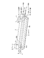
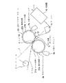
図7、図8に基づき、本発明の実施例3に係る塗工装置を以下説明する。図7は、本実施例の塗工装置の模式的な側面図であり、図8は本実施例のボックス部およびエゼクタの配置を示す斜視図である。本実施例においては、ボックス部の構成が異なる他は実施例1と同様であり、同様部分には同符号を付し説明を簡略とし、実施例1と異なる点を主に以下説明する。 A coating apparatus according to Example 3 of the present invention will be described below based on FIGS. FIG. 7 is a schematic side view of the coating apparatus of the present embodiment, and FIG. 8 is a perspective view showing the arrangement of the box portion and the ejector of the present embodiment. The present embodiment is the same as the first embodiment except that the configuration of the box portion is different. The same parts are denoted by the same reference numerals to simplify the description, and differences from the first embodiment will be mainly described below.
本実施例においては、図7、図8に示すように、下部アプリケータロール2aの回転方向においてニップ部4の上流側でニップ部4と下部コータヘッド3aとの間に、下部アプリケータロール2aの略全幅にわたって(あるいは、少なくとも塗工するウエブ1を覆うように)、下部アプリケータロール2aの回転に伴う同伴空気流を阻止するために、下部アプリケータロール2a表面へ上流方向にエゼクタ気体aを噴射する(第1のエゼクタとしての)ノズル18aを有する本発明における「空気流入防止手段」の一つとしてのエゼクタ18が設けられている。
In this embodiment, as shown in FIGS. 7 and 8, the
エゼクタ18は、また、ウエブ1側の同伴空気流を阻止するために、ウエブ1の走行方向においてニップ部4の上流側に、ウエブ1の下部アプリケータロール2aと接する側の面へ上流方向にエゼクタ気体aを噴射する(第2のエゼクタとしての)ノズル18bも有しており、ノズル18aとノズル18bの間を一体に塞いでいる。ノズル18bはペーパーロール7近傍で噴射することがウエブ1の安定上好ましい。
The ejector 18 also upstream of the nip portion 4 in the running direction of the
エゼクタ18は、図7に示されるように、閉塞した筒状中空体に上記のノズル18a、18bを設けたものであり、ノズル18aの向き(噴射方向)は下部アプリケータロール2aの噴射される位置での接線方向に対して10°〜45°程度、ノズル18bの向き(噴射方向)はウエブ1の噴射される位置の表面(ロール上にあって曲面の場合は接線方向)に対し10°ないし45°程度であり、塗工液やウエブ速度、下部アプリケータロール2a回転速度等によって設定され、ノズル18a、18bは、スリット状、多孔列等に形成される。噴射方向の範囲の作用効果については実施例1で説明したとおりである。
As shown in FIG. 7, the ejector 18 is provided with the above-described
エゼクタ18の筒状中空体内には、図7に略図示するように、適宜のエゼクタ気体供給装置11からエゼクタ気体aが供給される。エゼクタ気体aやその速度等に関しては実施例1同様である。
The ejector gas a is supplied from an appropriate ejector
また、図7、図8に示すように、下部アプリケータロール2aの回転方向においてニップ部4の上流側でニップ部4と下部コータヘッド3aとの間に、エゼクタ18が前述の実施例1のボックス正面板10aに代えて正面板部30aとなって上流側の壁となり、ニップ部4上流側のウエブ1がノズル18bの位置から下部アプリケータロール2aに接する位置4aまでを、前述の実施例1のボックス天板10cに代えて下流側の壁となる天板部30cとなり、下部アプリケータロール2aの左右方向に断面山形のボックス部30を本発明の「空気流入防止手段」の一つとして形成して、下部アプリケータロール2aの円周面表面の一部を覆うように設けられている。
Further, as shown in FIGS. 7 and 8, the ejector 18 is provided between the nip portion 4 and the
正面板部30aとなるエゼクタ18は、下部アプリケータロール2aの略全幅にわたる(少なくとも塗工するウエブ1を覆う)幅を有している。また、エゼクタ18は一体に形成することに代えてノズル18aを備える側とノズル18bを備える側とに分けて形成し、その間を密閉するように接続して一体化してもよい。
The ejector 18 serving as the front plate portion 30a has a width that covers substantially the entire width of the
ボックス部30は内部に空気の流入が少ないほうが好ましく、ボックス部30の左右の端部となるウエブ1による天板部30cの左右の端部には山形断面の開口を塞ぐようにボックス端板30bが設けられ、ボックス部30の幅が十分でない場合は特に効果がある。また、エゼクタ18、ボックス端板30bの下縁は、塗工液を塗布された下部アプリケータロール2aと接触しない程度に間隔をあけて近接して設置すると好ましい。ボックス端板30bは下部アプリケータロール2aの軸方向(幅方向)に可動構造として、ウエブ1による天板部30cの幅に合わせた位置に位置調整の上設定できるようにするのが好ましく、その場合、天板部30cの左右に開口が生じず、ボックス部30内への空気の流入をより効果的に防止できる。
It is preferable that the box portion 30 has a small amount of air flowing therein, and the
ボックス部30には、好ましくは通気口30dが設けられ、通気口30dに接続する通気管を、図7に略図示するように、吸引装置12に接続しボックス部20内の気体bを吸引するように構成し、またあるいは、図7に略図示するように、蒸気供給装置13に接続しボックス部30内へ蒸気cを供給するように構成する。通気口30dは、ボックス端板30bかエゼクタ18を貫通して適宜設けられ、その位置は限定されないが、流入空気の排出箇所としては最も流入しやすいボックス部30両端でボックス端板30bに設けることが効果的である。ボックス端板30bを可動とする作用効果は実施例2で説明したと同様である。
The box portion 30 is preferably provided with a vent hole 30d, and a vent pipe connected to the vent hole 30d is connected to the
上記のように構成された本実施例の塗工装置においては、下部アプリケータロール2a
の回転に伴う同伴空気流は、(第1のエゼクタとしての)エゼクタ18のノズル18aから噴射されるエゼクタ気体aによって阻止され、ウエブ1の搬送に伴う同伴空気流は、(第2のエゼクタとしての)エゼクタ18のノズル18bから噴射されるエゼクタ気体aによって阻止され、しかもニップ部4上流側のウエブ1の下部アプリケータロール2aと接する側の面がボックス部30内に面し、外部に面しないので、ウエブ1と下部アプリケータロール2a間に同伴空気流が巻き込まれることがより効果的に防止される。
In the coating apparatus of the present embodiment configured as described above, the
The entrained air flow accompanying the rotation of the
また、ブレード9に代えて、ウエブ1側の同伴空気流の阻止を第2のエゼクタ18aにしたことにより、ウエブ1に非接触で同伴空気流阻止を行うことができ、ウエブ1の断紙の恐れがなくなる。
Further, the
しかしながら、下部アプリケータロール2a側の第1のエゼクタ18aとウエブ1側の第2のエゼクタとからエゼクタ気体aの噴射を行うので、その背面側の負圧は増加する傾向となり、ボックス部30内の負圧はウエブ1の下部アプリケータロール2aへの吸着を促進する効果がある一方、ボックス部30が周囲に対して開放されていると、周囲からボックス部30内へ空気が流入し同伴空気流を再発生し、エゼクタ18の同伴空気流阻止の効果を減じる恐れが高まる。
However, since the ejector gas a is injected from the
そこで、ボックス部30の左右の端部に山形断面の開口を塞ぐようにボックス端板30bを設け、第1のエゼクタ18aとボックス端板30bの下縁を、塗工液を塗布された下部アプリケータロール2aに接触しない程度に間隔をあけて近接して設置し、第2のエゼクタ18bをウエブ1に接触しない程度に間隔をあけて近接して設置することが特に有効であり、その構成により空気の流入を減じることができ流入空気による同伴空気流の再発生を防ぐことができる。
Therefore, a
ここで、実施例1と同様に、ボックス部30に通気口30dを設け、通気口30dに接続する通気管を吸引装置12に接続しボックス部30内の気体b(通常は空気)を吸引するように構成すれば、ボックス部30に流入した空気を排出することにより流入空気による同伴空気流の再発生がより効果的に防止される。また、ボックス部30内の負圧を維持できるので、ウエブ1による天板部30cが下部アプリケータロール2a方向に吸引され、ウエブ1の下部アプリケータロール2aに対する吸着性が向上する。
Here, as in the first embodiment, the box portion 30 is provided with a vent 30d, and a vent pipe connected to the vent 30d is connected to the
または、通気口30dに接続する通気管を蒸気供給装置13に接続しボックス部30内へ蒸気cを供給するように構成すれば、ボックス部30内の空気の多くを蒸気cに置換するとともに微正圧に設定することで、空気の流入を防止でき、蒸気の同伴流は発生しても下部アプリケータロール2aとウエブ1の表面の境界層では凝縮により負圧を発生し、ウエブ1の下部アプリケータロール2aに対する吸着性が向上する。また、ウエブ1が蒸気の凝縮により濡れ性が上がり、塗工液被覆率が上がって塗工品質が向上する。
Alternatively, if the vent pipe connected to the vent 30d is connected to the
なお、エゼクタ18のエゼクタ気体aとしては、空気が一般的に適用できるが、蒸気をや不活性ガス等を用いれば、実施例1で説明したと同様の作用効果がある。 Note that air is generally applicable as the ejector gas a of the ejector 18, but if steam or an inert gas is used, the same effects as those described in the first embodiment can be obtained.
以上のように本実施例においても、ウエブ1の同伴空気流のみならず下部アプリケータロール2aの同伴空気流を共に除くことができるので塗工液とウエブ1との接触が阻害されず、ウエブ1の下部アプリケータロール2aに対する吸着性が効果的に向上し、塗工むらやミスティングが減少してウエブ1の塗工状態が向上する。
As described above, also in this embodiment, not only the entrained air flow of the
また、以上のようにニップ部4の上流側の塗工状態が改善され、ニップ部4の上流側、下流側の塗工状態を等しくすることが容易であるので、ウエブ1両面の塗工状態が揃って品質向上が図られる。 Further, as described above, the coating state on the upstream side of the nip portion 4 is improved, and it is easy to make the coating state on the upstream side and downstream side of the nip portion 4 equal. As a result, quality can be improved.
以上、本発明の実施例を説明したが、本発明は上記の実施例に限定されるものではなく、本発明の範囲内でその具体的構造に種々の変更を加えてもよいことは言うまでもない。 As mentioned above, although the Example of this invention was described, this invention is not limited to said Example, It cannot be overemphasized that a various change may be added to the specific structure within the scope of the present invention. .
例えば、各実施例の図示における上下の配置は一例に過ぎず、図示とは上下逆にした配置とし、コータヘッドの向きをそれに合わせた向きとしたものであってもよく、その場合、ボックス部10、20、30における天板10c、天板部20c、30cとは、鉛直方向上端位置にあることを意味するのではなく、下方に位置してもアプリケータロールの周面の一部を覆う位置関係にある板または板状部分を示すものであることは勿論である。 For example, the upper and lower arrangements in the illustrations of the embodiments are merely examples, and the arrangement may be reversed upside down from the illustrations, and the orientation of the coater head may be in accordance with the arrangement. The top plate 10c and the top plate portions 20c and 30c in 10, 20, and 30 do not mean that they are in the upper end position in the vertical direction, but cover a part of the peripheral surface of the applicator roll even if they are positioned below. Of course, this indicates a plate or plate-like portion in a positional relationship.
また、上記実施例は皆、互いに圧接してニップ部を形成する2本のアプリケータロールを備え、そのニップ部を通過するウエブ表面上にその2本のアプリケータロール上の塗工液を転写、塗布する塗工装置を示したが、請求項1ないし請求項13の本発明はそれに限定されることなく、例えば従来例の図10に示したもののように、バッキングロール(本発明における「他のロール」)と互いに圧接してニップ部を形成する1本のアプリケータロール(本発明における「アプリケータロール」)を備え、そのニップ部を通過するウエブ表面上にそのアプリケータロール上の塗工液を転写、塗布する塗工装置においても適用でき、その作用効果を奏し得るものである。勿論その場合、塗工液供給手段は図10のようにカーテンダイによるものでなく、コータヘッド等他の塗工液供給手段による塗工装置でもよい。
In addition, each of the above embodiments is provided with two applicator rolls that are pressed against each other to form a nip portion, and the coating liquid on the two applicator rolls is transferred onto the web surface that passes through the nip portion. However, the present invention of
もっとも、本発明は2本のアプリケータロールを備え、そのニップ部を通過するウエブの両面の表面上にその2本のアプリケータロール上の塗工液を転写、塗布する塗工装置において、より有効にその作用効果を奏することができるのであって、ニップ部の上流側の塗工状態が改善され、ニップ部の上流側、下流側の塗工状態を等しくすることが容易であるので、ウエブ両面の塗工状態が揃って品質向上が図られる。 However, the present invention is a coating apparatus that includes two applicator rolls, and transfers and coats the coating liquid on the two applicator rolls on both surfaces of the web that passes through the nip portion. It is possible to effectively achieve the effect, the coating state on the upstream side of the nip portion is improved, and it is easy to equalize the coating state on the upstream side and downstream side of the nip portion. The coating state on both sides is aligned and the quality is improved.
また、請求項1ないし請求項13の本発明は、各実施例に示したような、ウエブをアプリケータロールに抱かせるように配置したものに限定されず、図1、5、7、9に破線でウエブ1を示したように、ウエブが2つのロールの間のニップ部を接線方向に通過するように配置された場合の塗工装置としても実施でき、その作用効果を奏し得る。
Further, the present invention of
一般に、他のロールとアプリケータロールとがニップ部を形成し、同ニップ部を通過するウエブの表面にアプリケータロール上の塗工液を転写塗布する塗工装置においては、通常、ニップ力を変化させ塗工液のウエブ表面への転写率を制御する。塗工性能を保持したまま装置の高速化をはかるには、高速化に伴うウエブとアプリケータロール表面の同伴空気流のニップ部への噛み込み増加を防止するために、ニップ力を増加させる必要があった。しかし、そうすると、高ニップ圧のために所定の塗工膜厚を塗工できないという問題が発生するが、請求項1ないし請求項13の本発明の塗工装置によれば、その空気流入防止手段により、高速化によるニップ部への伴流の噛み込みを防止でき、従って、徒にニップ圧を高くする必要が無く、所定の膜厚の塗工が可能となる。
In general, in a coating apparatus in which another roll and an applicator roll form a nip portion, and the coating liquid on the applicator roll is transferred onto the surface of the web passing through the nip portion, the nip force is usually applied. Change the transfer rate of the coating liquid to the web surface. In order to increase the speed of the machine while maintaining the coating performance, it is necessary to increase the nip force in order to prevent the entrained air flow of the web and applicator roll surface from encroaching into the nip as the speed increases. was there. However, this causes a problem that a predetermined coating film thickness cannot be applied due to the high nip pressure. According to the coating apparatus of the present invention of
1 ウエブ
2a 下部アプリケータロール
2b 上部アプリケータロール
3a 下部コータヘッド
3b 上部コータヘッド
4 ニップ部
5 ロール側ターンバー
6 ターンバー
7 ペーパーロール
8 エゼクタ
8a ノズル
9 ブレード
10 ボックス部
10a ボックス正面板
10b ボックス端板
10c ボックス天板
10d 通気口
11 エゼクタ気体供給装置
12 吸引装置
13 蒸気供給装置
18 エゼクタ
18a ノズル
18b ノズル
20 ボックス部
20a ボックス正面板
20b ボックス端板
20c 天板部
20d 通気口
30 ボックス部
30a 正面板部
30b ボックス端板
30c 天板部
30d 通気口
40 乾燥器
51 カーテンダイ
52 アプリケータロール
53 バッキングロール
54 ニップ部
DESCRIPTION OF
Claims (14)
同アプリケータロールの回転方向における前記ニップ部の上流側に設けられ同アプリケータロールの表面に向けて塗工液を供給する塗工液供給手段と、
前記ニップ部の上流側で同ニップ部と前記塗工液供給手段との間に設けられ、同ニップ部への空気の流入を防止する空気流入防止手段とを具備し、
同空気流入防止手段は、
前記アプリケータロールの表面へ同アプリケータロールの回転方向と反対方向に向かってエゼクタ気体を噴射するエゼクタを有してなることを特徴とする塗工装置。 In an application device comprising an applicator roll that presses against each other to form a nip, and transfers and applies the coating liquid on the applicator roll onto the web surface that passes through the nip.
A coating liquid supply means for supplying a coating liquid toward the surface of the applicator roll provided on the upstream side of the nip portion in the rotation direction of the applicator roll;
An air inflow prevention means provided between the nip portion and the coating liquid supply means on the upstream side of the nip portion to prevent the inflow of air into the nip portion;
The air inflow prevention means
A coating apparatus comprising: an ejector that ejects ejector gas toward the surface of the applicator roll in a direction opposite to the rotation direction of the applicator roll.
前記エゼクタ気体が蒸気であることを特徴とする塗工装置。 In the coating device according to claim 1,
The coating apparatus, wherein the ejector gas is steam.
前記エゼクタのノズルの噴射方向が、前記アプリケータロールの接線方向に対して10ないし45°を向くことを特徴とする塗工装置。 In the coating device according to claim 1 or 2,
The coating apparatus according to claim 1, wherein the ejecting direction of the nozzle of the ejector is 10 to 45 degrees with respect to a tangential direction of the applicator roll.
前記空気流入防止手段は、
前記ウエブの走行方向において前記ニップ部より上流側で前記ウエブの前記アプリケータロールに接する側の面に同ウエブ幅方向で接して設けられるブレードを有してなることを特徴とする塗工装置。 In the coating device according to any one of claims 1 to 3,
The air inflow prevention means includes
A coating apparatus comprising: a blade provided in contact with a surface of the web in contact with the applicator roll on the upstream side of the nip portion in the running direction of the web in the web width direction.
前記空気流入防止手段は、
前記エゼクタと前記ブレードとの間を塞ぐボックス正面板を有し、
前記アプリケータロールの回転方向における前記ニップ部の上流側で同ニップ部と前記エゼクタとの間に、
同ブレードと接する位置から前記アプリケータロールと接する位置までのウエブが形成する天板部と前記ボックス正面板と前記ブレードとが、前記ウエブの塗工される幅より広い幅を有して前記アプリケータロールの軸方向に沿って同アプリケータロールの円周面の一部を覆うように配置されたボックス部を形成し、
前記ボックス正面板および前記エゼクタは、塗工液を塗布された前記アプリケータロールと接触しない程度の間隔で近接して設置されてなることを特徴とする塗工装置。 In the coating device according to claim 4,
The air inflow prevention means includes
A box front plate that closes between the ejector and the blade;
Between the nip portion and the ejector on the upstream side of the nip portion in the rotation direction of the applicator roll,
The top plate portion formed by the web from the position in contact with the blade to the position in contact with the applicator roll, the box front plate, and the blade have a width wider than the width to which the web is applied. Forming a box portion arranged so as to cover a part of the circumferential surface of the applicator roll along the axial direction of the talol;
The box front plate and the ejector are installed close to each other at an interval so as not to contact the applicator roll coated with a coating liquid.
前記空気流入防止手段は、
前記エゼクタと前記ブレードとの間を塞ぐボックス正面板と、ボックス正面板の下流側に同ボックス正面板と接続して前記ウエブと前記アプリケータロールとの接触点に向かって延設されたボックス天板とを有し、
前記アプリケータロールの回転方向における前記ニップ部の上流側で同ニップ部と前記エゼクタとの間に、
前記ボックス天板と前記ボックス正面板とが、前記ウエブの塗工される幅より広い幅を有して前記アプリケータロールの軸方向に沿って同アプリケータロールの円周面の一部を覆うように配置されたボックス部を形成し、
前記ボックス正面板および前記エゼクタは、塗工液を塗布された前記アプリケータロールと接触しない程度の間隔で近接して設置されてなることを特徴とする塗工装置。 In the coating device according to claim 4,
The air inflow prevention means includes
A box front plate that blocks between the ejector and the blade; and a box ceiling that is connected to the box front plate on the downstream side of the box front plate and extends toward a contact point between the web and the applicator roll. A board,
Between the nip portion and the ejector on the upstream side of the nip portion in the rotation direction of the applicator roll,
The box top plate and the box front plate cover a part of the circumferential surface of the applicator roll along the axial direction of the applicator roll having a width wider than the width to which the web is applied. Form a box part arranged as
The box front plate and the ejector are installed close to each other at an interval so as not to contact the applicator roll coated with a coating liquid.
第1のエゼクタとしての前記エゼクタと、
前記ブレードに代えて、前記ウエブの走行方向におけるニップ部の上流側に設けられ、前記ウエブの前記アプリケータロールに接する側の面へ上流方向にエゼクタ気体を噴射する第2のエゼクタとを有してなることを特徴とする塗工装置。 In the coating device according to claim 4,
The ejector as a first ejector;
In place of the blade, a second ejector is provided on the upstream side of the nip portion in the running direction of the web, and ejects ejector gas in the upstream direction to the surface of the web in contact with the applicator roll. The coating apparatus characterized by comprising.
前記第2のエゼクタのノズルの噴射方向が、前記ウエブの表面に対して10ないし45°を向くことを特徴とする塗工装置。 In the coating device according to claim 7,
The coating apparatus according to claim 1, wherein the nozzle ejecting direction of the second ejector is 10 to 45 degrees with respect to the surface of the web.
前記第1のエゼクタと第2のエゼクタとの間が塞がれて正面板部を形成し、
前記アプリケータロールの回転方向における前記ニップ部の上流側で同ニップ部と前記エゼクタとの間に、
前記第2のエゼクタに面する位置から前記アプリケータロールと接する位置までのウエブが形成する天板部と前記正面板部とが、前記ウエブの塗工される幅より広い幅を有して前記アプリケータロールの軸方向に沿って同アプリケータロールの円周面の一部を覆うように配置されたボックス部を形成し、
前記正面板部および前記第1のエゼクタは、塗工液を塗布された前記アプリケータロールと接触しない程度の間隔で近接して設置され、
前記第2のエゼクタは前記ウエブと接触しない程度の間隔で近接して設置されてなることを特徴とする塗工装置。 In the coating device according to claim 7 or 8,
Between the first ejector and the second ejector is closed to form a front plate part,
Between the nip portion and the ejector on the upstream side of the nip portion in the rotation direction of the applicator roll,
The top plate portion formed by the web from the position facing the second ejector to the position in contact with the applicator roll and the front plate portion have a width wider than the width to which the web is applied. Forming a box portion arranged so as to cover a part of the circumferential surface of the applicator roll along the axial direction of the applicator roll;
The front plate portion and the first ejector are installed close to each other so as not to come into contact with the applicator roll coated with a coating liquid,
2. The coating apparatus according to claim 1, wherein the second ejector is disposed close to the web so as not to contact the web.
前記空気流入防止手段は、
前記ボックス部の前記アプリケータロール軸方向の両端部にそれぞれボックス端板を備え、
同ボックス端板は、塗工液を塗布された前記アプリケータロールと接触しない程度の間隔で近接して設置されてなることを特徴とする塗工装置。 In the coating apparatus according to claim 5, claim 6, or claim 9,
The air inflow prevention means includes
A box end plate is provided at each end of the box portion in the applicator roll axial direction,
The box end plate is installed close to the applicator roll coated with a coating solution at an interval that does not contact the applicator roll.
前記ボックス端板は、
前記アプリケータロール軸方向に移動可能に設けられてなることを特徴とする塗工装置。 The coating apparatus according to claim 10, wherein
The box end plate is
A coating apparatus characterized by being provided so as to be movable in the axial direction of the applicator roll.
前記空気流入防止手段は、
前記ボックス部に設けられた通気口を有し、
同通気口は同ボックス部内の気体を吸引する吸引装置に接続されてなることを特徴とする塗工装置。 In the coating device according to claim 10 or 11,
The air inflow prevention means includes
Having a vent provided in the box part;
The coating device is characterized in that the air vent is connected to a suction device for sucking the gas in the box portion.
前記空気流入防止手段は、
前記ボックス部に設けられた通気口を有し、
同通気口は同ボックス部内へ蒸気を供給する蒸気供給装置に接続されてなることを特徴とする塗工装置。 In the coating device according to claim 10 or 11,
The air inflow prevention means includes
Having a vent provided in the box part;
The air vent is connected to a steam supply device that supplies steam into the box portion.
同ニップ部通過後の同ウエブを同2本のアプリケータロールのうち一方のアプリケータロールの表面に抱かせた状態で同ウエブを移送させる空気浮上式ターンバーが同ニップ下流側に設けられ、
同ニップ部よりも同ウエブの走行方向上流側に、同ニップ部通過前の同ウエブを前記一方のアプリケータロールとは反対側の他方のアプリケータロールの表面に抱かせた状態で同ウエブを移送させるペーパーロールが設けられ、
同ウエブと前記他方のアプリケータロールの表面との接触部よりも同ウエブの走行方向上流側であって同ウエブと前記他方のアプリケータロールの表面との間に前記ニップ部への空気の流入を防止する空気流入防止手段を具備してなることを特徴とする塗工装置。 In a coating apparatus that includes two applicator rolls that press against each other to form a nip portion, and transfers and applies the coating liquid on the two applicator rolls onto the web surface that passes through the nip portion.
An air levitated turn bar is provided on the downstream side of the nip to transfer the web in a state where the web after passing through the nip is held on the surface of one of the two applicator rolls.
In the state where the web before passing the nip portion is held on the surface of the other applicator roll opposite to the one applicator roll, on the upstream side of the nip portion in the running direction of the web. A paper roll to be transported is provided,
Inflow of air into the nip portion between the web and the surface of the other applicator roll, which is upstream of the contact portion between the web and the surface of the other applicator roll in the running direction of the web. A coating apparatus comprising an air inflow prevention means for preventing water.
Priority Applications (4)
| Application Number | Priority Date | Filing Date | Title |
|---|---|---|---|
| JP2004112927A JP2005296723A (en) | 2004-04-07 | 2004-04-07 | Applicator |
| CNB2004100926533A CN100377792C (en) | 2004-04-07 | 2004-11-15 | Coating apparatus |
| US11/099,548 US7323056B2 (en) | 2004-04-07 | 2005-04-06 | Coating apparatus |
| EP05007526A EP1584377A3 (en) | 2004-04-07 | 2005-04-06 | Coating apparatus |
Applications Claiming Priority (1)
| Application Number | Priority Date | Filing Date | Title |
|---|---|---|---|
| JP2004112927A JP2005296723A (en) | 2004-04-07 | 2004-04-07 | Applicator |
Publications (1)
| Publication Number | Publication Date |
|---|---|
| JP2005296723A true JP2005296723A (en) | 2005-10-27 |
Family
ID=34909502
Family Applications (1)
| Application Number | Title | Priority Date | Filing Date |
|---|---|---|---|
| JP2004112927A Withdrawn JP2005296723A (en) | 2004-04-07 | 2004-04-07 | Applicator |
Country Status (4)
| Country | Link |
|---|---|
| US (1) | US7323056B2 (en) |
| EP (1) | EP1584377A3 (en) |
| JP (1) | JP2005296723A (en) |
| CN (1) | CN100377792C (en) |
Families Citing this family (14)
| Publication number | Priority date | Publication date | Assignee | Title |
|---|---|---|---|---|
| US20100129571A1 (en) * | 2008-11-25 | 2010-05-27 | Precisionjet, Inc. | Method for making artificial turf |
| US8647452B2 (en) * | 2008-11-25 | 2014-02-11 | John H. Bearden | Method for making artificial turf |
| JP4825295B2 (en) | 2009-10-21 | 2011-11-30 | 日高精機株式会社 | Processing oil application equipment |
| US8968502B1 (en) * | 2009-11-06 | 2015-03-03 | John H. Bearden | Method for coating a tufted athletic turf backing |
| CN102493280A (en) * | 2011-12-02 | 2012-06-13 | 牡丹江恒丰纸业股份有限公司 | Device and method for manufacturing cigarette paper with flame-retardant belt |
| US9539605B2 (en) * | 2012-02-28 | 2017-01-10 | Toray Plastics (America), Inc. | Gravure roll edge masking system for in-line film coating |
| CN107743423B (en) * | 2015-06-12 | 2021-09-07 | 3M创新有限公司 | Method and apparatus for liquid coating using deformable metal rollers |
| JP6932520B2 (en) * | 2016-03-08 | 2021-09-08 | 住友化学株式会社 | Manufacturing method for doctor blades, coating equipment and laminated separators |
| CN106583149A (en) * | 2017-02-27 | 2017-04-26 | 领胜城科技(江苏)有限公司 | Closed material supply comma coating device |
| CN112221765B (en) * | 2020-11-05 | 2025-03-07 | 佛山鑫炜自动设备科技有限公司 | A drum oiling and feeding mechanism |
| CN113617582A (en) * | 2021-07-05 | 2021-11-09 | 芜湖夏鑫新型材料科技有限公司 | Photoelectric protection film and photoelectric protection film rubber coating device |
| CN113617585A (en) * | 2021-09-17 | 2021-11-09 | 佛山市环宇新型材料有限公司 | Coating machine with fire fighting equipment |
| WO2023057796A1 (en) * | 2021-10-07 | 2023-04-13 | Arcelormittal | Process and apparatus for manufacturing a steel strip for electrical applications |
| CN114011645B (en) * | 2021-10-08 | 2024-01-23 | 安徽瑞露科技有限公司 | Battery pole piece coating device |
Family Cites Families (8)
| Publication number | Priority date | Publication date | Assignee | Title |
|---|---|---|---|---|
| DE4205312A1 (en) * | 1992-02-21 | 1993-08-26 | Voith Gmbh J M | ROLLER APPLICATION DEVICE FOR APPLYING COATING INK ON A PAPER RAIL |
| JPH06238219A (en) * | 1993-02-16 | 1994-08-30 | Konica Corp | Coating method and apparatus |
| JP3428006B2 (en) * | 1994-11-16 | 2003-07-22 | 日本製紙株式会社 | Application method |
| DE19702605A1 (en) * | 1997-01-24 | 1998-07-30 | Voith Sulzer Papiermasch Gmbh | Device and method for the direct or indirect application of a liquid or pasty medium to a running material web |
| DE19800954A1 (en) * | 1998-01-13 | 1999-07-15 | Voith Sulzer Papiertech Patent | Device for direct or indirect application of a liquid or pasty application medium to a running material web, in particular made of paper or cardboard |
| JP2002263549A (en) * | 2001-03-13 | 2002-09-17 | Mitsubishi Heavy Ind Ltd | Coating apparatus and production of coated paper |
| JP3836068B2 (en) * | 2002-03-05 | 2006-10-18 | 三菱重工業株式会社 | Air-floating web running support device and coating device using the same |
| JP4059709B2 (en) * | 2002-05-29 | 2008-03-12 | 富士フイルム株式会社 | Thin film coating method and apparatus |
-
2004
- 2004-04-07 JP JP2004112927A patent/JP2005296723A/en not_active Withdrawn
- 2004-11-15 CN CNB2004100926533A patent/CN100377792C/en not_active Expired - Fee Related
-
2005
- 2005-04-06 US US11/099,548 patent/US7323056B2/en not_active Expired - Fee Related
- 2005-04-06 EP EP05007526A patent/EP1584377A3/en not_active Withdrawn
Also Published As
| Publication number | Publication date |
|---|---|
| US20050223974A1 (en) | 2005-10-13 |
| EP1584377A3 (en) | 2008-05-28 |
| EP1584377A2 (en) | 2005-10-12 |
| US7323056B2 (en) | 2008-01-29 |
| CN100377792C (en) | 2008-04-02 |
| CN1680044A (en) | 2005-10-12 |
Similar Documents
| Publication | Publication Date | Title |
|---|---|---|
| JP2005296723A (en) | Applicator | |
| TWI221098B (en) | Liquid spray applicator and liquid spray applicating method thereof | |
| EP1242684B1 (en) | Curtain coater and method for curtain coating | |
| FI115314B (en) | Apparatus for processing paper or cardboard | |
| CN103835187B (en) | For processing the equipment of fiber web | |
| US20110074869A1 (en) | Ink-jet wiping apparatus, and wiping method using this | |
| CN109373743B (en) | Air knife and drying device adopting same | |
| JPH11256500A (en) | Apparatus for applying liquid or pasty coating medium to traveling material web | |
| JP2011050816A (en) | Edge guide for curtain coater | |
| JP2005161153A (en) | Double coating apparatus | |
| JP3836068B2 (en) | Air-floating web running support device and coating device using the same | |
| JPH07132270A (en) | Liquid removing device | |
| JP2005246194A (en) | Double-side coating device | |
| JP2002263549A (en) | Coating apparatus and production of coated paper | |
| JP5228227B2 (en) | Curtain coater edge guide | |
| FI105119B (en) | An arrangement and method for preventing a jet of a spray nozzle from being directed to a paper web | |
| JP5306769B2 (en) | Film surface treatment equipment | |
| JP2006263536A (en) | Coating apparatus | |
| JP3182815U (en) | Coating nozzle cleaning device | |
| JP4778303B2 (en) | Building board painting equipment | |
| JP4639705B2 (en) | Depressurized web tension die coater | |
| JPH0615761U (en) | Coating equipment | |
| JP3702128B2 (en) | Coating equipment | |
| JP4129861B2 (en) | Coating equipment | |
| JPH09314016A (en) | Assembly for prevention of clogging in nozzle of coating machine |
Legal Events
| Date | Code | Title | Description |
|---|---|---|---|
| A300 | Application deemed to be withdrawn because no request for examination was validly filed |
Free format text: JAPANESE INTERMEDIATE CODE: A300 Effective date: 20070703 |