JP2005296544A - dishwasher - Google Patents
dishwasher Download PDFInfo
- Publication number
- JP2005296544A JP2005296544A JP2004121221A JP2004121221A JP2005296544A JP 2005296544 A JP2005296544 A JP 2005296544A JP 2004121221 A JP2004121221 A JP 2004121221A JP 2004121221 A JP2004121221 A JP 2004121221A JP 2005296544 A JP2005296544 A JP 2005296544A
- Authority
- JP
- Japan
- Prior art keywords
- float
- switch
- support
- water
- dishwasher
- Prior art date
- Legal status (The legal status is an assumption and is not a legal conclusion. Google has not performed a legal analysis and makes no representation as to the accuracy of the status listed.)
- Pending
Links
Images


Landscapes
- Washing And Drying Of Tableware (AREA)
Abstract
【課題】水位変動に応じてフロートの浮き沈み作動が円滑に行われ、スイッチに誤動作が生じ難い食器洗い機を提供する。
【解決手段】フロート水溜めケース24は細長の箱型形状をなし、支持部材の支持軸271に回動自在に支持される支持ボス502を一端側に有し、他端側にフロートを可動自在に連結支持する連結支持部501を有するフロート用連結アーム50は、回動に応じて前記スイッチのオン・オフ操作を行う操作腕503を有し、フロート体は、細長の箱型形状をしたフロート部と、フロート部の上側に立ち上がる支持柱252を有し、支持柱252の上端に頭部253を設け、この頭部は少なくとも下面側が円弧形状を有し、フロート用連結アーム50の連結支持部501は、頭部の下面を摺動自在に支持する円弧形状の窪みを有し、頭部、および前記窪みに形成される円弧形状の円弧軸心方向が前記フロート水溜めケース24の長手方向と交差するように配置されていること。
【選択図】図3An object of the present invention is to provide a dishwasher in which a float can be smoothly lifted and lowered in response to a fluctuation in water level, and a malfunction of a switch hardly occurs.
A float water reservoir case 24 has an elongated box shape, and has a support boss 502 supported on a support shaft 271 on one end of a support member so that the float can move freely on the other end. A float connection arm 50 having a connection support portion 501 connected to and supported by an actuator has an operation arm 503 for turning the switch on and off in response to rotation, and the float body is a float having a slender box shape. And a support column 252 rising above the float unit, and a head 253 is provided at the upper end of the support column 252. This head has an arc shape on at least the lower surface side, and the connection support unit of the connection arm 50 for the float 501 has an arc-shaped depression that slidably supports the lower surface of the head, and the arc-shaped arc axis direction formed in the depression and the depression is the longitudinal direction of the float reservoir case 24. Be placed so that they intersect.
[Selection] Figure 3
Description
本発明は、洗浄槽内の水位検知のためにフロートスイッチを設けた食器洗い機に関する。 The present invention relates to a dishwasher provided with a float switch for detecting a water level in a washing tank.
洗浄槽内の水位検知のためにフロートスイッチを設けた食器洗い機は、特開平7−31573号公報(特許文献1)で示されている。 A dishwasher provided with a float switch for detecting the water level in the washing tank is disclosed in Japanese Patent Application Laid-Open No. 7-31573 (Patent Document 1).
その食器洗い機は、洗浄槽と、この洗浄槽内に備えられる食器収納かごと、洗浄水を前記洗浄槽内に向けて噴射する回転噴射体と、吸い込み/加圧した洗浄水を前記回転噴射体に供給する洗浄ポンプと、前記洗浄槽の下方に備わる水貯留部の水位を検出するフロートスイッチを備え、前記フロートスイッチは、前記水貯留部に連通するフロート水溜めケースと、このフロート水溜めケース内に浮くように置かれるフロート体と、このフロート体の浮き沈みに応じてオン・オフするスイッチを有する。 The dishwasher includes a washing tub, a dish storage case provided in the washing tub, a rotating sprayer for injecting cleaning water into the washing tub, and a suction / pressurized cleaning water for the rotating spraying body. And a float switch for detecting a water level of a water storage section provided below the cleaning tank, the float switch including a float water reservoir case communicating with the water storage portion, and the float water reservoir case A float body placed so as to float inside, and a switch that is turned on and off in accordance with the ups and downs of the float body.
フロート体の浮き沈みに連れてオン・オフの作動をするスイッチは、フロート用連結アームを介してフロート体と連結されている。フロート体とフロート用連結アームのつなぎは、自在継ぎ手のような連結手段が用いられているので、浮き沈みに際してフロート体がフロート水溜めケースの内壁面に接触する方向に安易に動いてフロートの浮き沈み作動が円滑に行われない恐れがある。 A switch that is turned on and off as the float body rises and falls is connected to the float body via a float connecting arm. The connection between the float body and the connection arm for the float uses a connecting means such as a universal joint. May not be carried out smoothly.
本発明は、上記の問題に対処し、水位変動に応じてフロート体の浮き沈み作動が円滑に行われ、スイッチに誤動作が生じ難い食器洗い機を提供することを目的とする。 It is an object of the present invention to provide a dishwasher that copes with the above-described problems and that allows the float body to smoothly move up and down in response to fluctuations in the water level and that does not cause malfunction of the switch.
本発明は、洗浄槽の下方に備わる水貯留部の水位を検出するフロートスイッチを備え、フロートスイッチは、水貯留部に連通するフロート水溜めケースと、このフロート水溜めケース内に浮くように置かれるフロート体と、このフロート体の浮き沈みに応じてオン・オフするスイッチを有する食器洗い機にあって、フロート水溜めケースは細長の箱型形状をなし、支持部材の支持軸に回動自在に支持される支持ボスを一端側に有し、他端側にフロートを可動自在に連結支持する連結支持部を有するフロート用連結アームは、回動に応じて前記スイッチのオン・オフ操作を行う操作腕を有し、フロート体は、細長の箱型形状をしたフロート部と、フロート部の上側に立ち上がる支持柱を有し、支持柱の上端に頭部を設け、この頭部は少なくとも下面側が円弧形状を有し、フロート用連結アームの連結支持部は、頭部の下面を摺動自在に支持する円弧形状の窪みを有し、頭部、および前記窪みに形成される円弧形状の円弧軸心方向が前記フロート水溜めケースの長手方向と交差するように配置されていることを特徴とする。 The present invention includes a float switch for detecting the water level of a water storage section provided below the cleaning tank, and the float switch is disposed so as to float in the float water storage case and a float water storage case communicating with the water storage section. In a dishwasher having a float body to be turned on and a switch that is turned on and off in accordance with the ups and downs of the float body, the float sump case has an elongated box shape and is supported rotatably on the support shaft of the support member The float connection arm has a support boss on one end side and a connection support portion for connecting and supporting the float movably on the other end side. The float body has an elongated box-shaped float part and a support column that rises above the float part, and a head is provided at the upper end of the support column. The surface side has an arc shape, and the connection support portion of the float connecting arm has an arc-shaped recess that slidably supports the lower surface of the head, and the arc-shaped recess formed in the head and the recess. The arc axis direction is arranged so as to intersect with the longitudinal direction of the float reservoir case.
本発明によれば、水位変動に応じてフロートの浮き沈み作動が円滑に行われる食器洗い機を提供できる。 ADVANTAGE OF THE INVENTION According to this invention, the dishwasher by which the up-and-down operation of a float is performed smoothly according to a water level fluctuation | variation can be provided.
本発明の実施形態に係る実施例について、図面に基づいて説明する。 Examples according to embodiments of the present invention will be described with reference to the drawings.
まず、図1を引用して本発明の実施例に係る食器洗い機の概要から述べる。 First, an outline of a dishwasher according to an embodiment of the present invention will be described with reference to FIG.
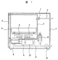
この食器洗い機は、外枠体1と、外枠体1の内側に備わる洗浄槽2と、洗浄槽2の前面側の開口を開閉自在なる蓋体3を有する。食器類が載せられる食器かご4は、洗浄槽2に出し入れ自在に備わる。
This dishwasher includes an
洗浄槽2の底側には、回転噴射体5が備わる。回転噴射体5の上側に食器かご4が置かれる。
A
洗浄槽2に給水する給水管6は電磁バルブ7を有する。電磁バルブ7の開け閉めで、給水、給水停止が行われる。
A
洗浄槽2の下方に水貯留部8が備わる。この水貯留部8に洗浄ポンプ9を介して回転噴射体5がつながる。洗浄ポンプ9は洗浄ポンプ電動機20で駆動される。洗浄ポンプ電動機20の駆動で、洗浄ポンプ9は水貯留部8の洗浄水を吸い込み、かつ加圧して回転噴射体5に送る。これにより、回転噴射体5から勢い良く洗浄水が噴射し、食器かご4に置かれる食器が洗われる。
A
水貯留部8に連通するようにつながる排水管21には、排水ポンプ22が設けられる。水貯留部8に溜まる洗浄水は排水ポンプ22で排水される。フロートスイッチ23は排水管21に連通するようにつながる。フロートスイッチ23は、水貯留部8の水位を検出する。
A
このフロートスイッチについて、図2〜図8を加えて詳しく説明する。 This float switch will be described in detail with reference to FIGS.
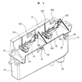
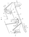
フロートスイッチ23は、フロート水溜めケース24、フロート水溜めケース内に浮くように置かれるフロート体25A/Bと、フロート体の浮き沈みに応じてオン・オフするスイッチ26A/Bを有する。フロート水溜めケース24の上に被さるフロートケースカバー35は、立ち上がるように形成される立壁27を有する。
The
フロート水溜めケース24の底側に連通口28が設けられ、この連通口28が排水管21に連通するようにつながる。水貯留部8に溜まる洗浄水は、排水管21、連通口28を介してフロート水溜めケース24に流れ込み、フロート水溜めケース24に溜まる洗浄水でフロート体25A/Bは浮く。
A
フロートケースカバー35は、注水管29を有する。この注水管29から水道水が注水される。この注水で、フロート水溜めケース24に着く汚れを落とすようにしている。また注水管29は、サイホンブレーカの機能も担っている。
The
フロートケースカバー35は、係止爪40、係止突起41を有する。フロート水溜めケース24は、係止爪40が係合する係合台42、係止突起41が係合する係合孔43を有する。この係止爪40、係止突起41、係合台42、および係合孔43は着脱係止手段を構成するもので、この着脱係止手段によりフロートケースカバー35はフロート水溜めケース24に取り外し自在に取り付けられる。
The
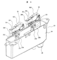
フロート水溜めケース24は、細長の箱型形状をしている。フロート水溜めケース24の内側に二つのフロート体25A/Bが置かれる。
The float
フロート体25Aとフロート体25Bは、丈の違いを除いて同じ構成を有する。
The
フロート体25Aは洗浄水位検知用(低水位検知用)、フロート体25Bは溢水水位検知用(高水位検知用)で、丈はフロート体25Aの方が高い。
The
フロート体25A/Bは、フロート部251、支持柱252を有する。フロート部251は、細長の箱型形状をしている。二つのフロート体は、フロート部251をフロート水溜めケースの長手方向に並ぶようにフロート水溜めケース内に置かれる。フロート部251の丈は、フロート体25Aが高い。
The float body 25 </ b> A / B includes a
支持柱252は、フロート部251の上側に立ち上がるように形成される。支持柱252は、上端に頭部253を有する。頭部253は下面側が円弧形状を有している。頭部253の上面は扁平であるが、円弧形状にすることも可能である。
The
支持柱252は、頭部253の下方に括れた首部254、首部254の下方に肩部255を有する。肩部255の下側は肩幅のままでフロート部251につづく形状になっている。肩部255の上面側は円弧形状を有する。
The
頭部253の円弧形状の円弧軸心方向と、肩部255の円弧形状の円弧軸心方向は同じ方向に設けられている。このため、頭部253の下面側と肩部255の上面側は首部254を介して円弧の頂点を突き合わせた構成になる。
The arc-shaped arc axis direction of the
フロートケースカバー35は、フロート体の支持柱252が挿入される柱挿入穴261を有する。柱挿入穴261への支持柱252の挿入は、フロートケースカバー35をフロート水溜めケース24に取り付ける前に行なう。
The
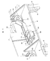
フロートケースカバー35の立壁27は支持部材になる。この支持部材の立壁27には、支持軸271が設けられる。支持軸271はフロートケースカバー35の上側に位置するように立壁27の表側に設けられる。脱落防止用係止片272は、支持軸271を挟むように対称位置に設けられる。脱落防止用係止片272の先端に内向きの爪273が設けられる。
The standing
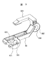
フロート用連結アーム50は、図7に示すように連結支持部501、支持ボス502、操作腕503を有する。連結支持部501はフロート用連結アーム50の一端に、支持ボス502はフロート用連結アーム50の他端に設けられる。フロート用連結アーム50は二つのフロート体に合わせて二つ備えられる。
As shown in FIG. 7, the
支持ボス502は軸受穴504を有する。フロート用連結アーム50は支持軸271に軸受穴504を嵌め込むことで、支持軸271に回転自在に支持される。脱落防止用係止片272の爪273が支持ボス502の外周寄り側縁部に係合するので、フロート用連結アーム50は脱落することなく、支持ボス502に回転自在に支持される。
The
脱落防止用係止片272の爪273は、先端内側に傾斜面を有する。この傾斜面は先端に向かって外周に広がるような傾きになっている。このため、フロート用連結アーム50の支持ボス502の軸受穴504を支持軸271に嵌める際に、外側から支持ボス502を強く押すことにより、脱落防止用係止片272が外周方向に開かれ、脱落防止用係止片272に抱きかかえられるように支持ボス502は嵌る。支持ボス502の支持軸271への取り付けが容易である。
The
図5は、フロート用連結アーム50がフロートケースカバー35に取り付けられたところを示す。操作腕503は、立壁27の両側に跨るように置かれる。操作腕503のつけ根(支持ボス502につながるところ)は、立壁27の表側に位置するが、操作腕503の先側を含む大部分は立壁27の裏側に位置する。
FIG. 5 shows the
スイッチ26A/Bは、立壁27の裏側に位置するように備わる。スイッチ26Aは、フロート体25Aに対応する洗浄水位検知用(低水位検知用)である。スイッチ26Bは、フロート体25Bに対応する溢水水位検知用(高水位検知用)である。
The
フロート体とスイッチは、立壁27を挟んで表裏に置かれるので、簡素な配置構成になり、組立がし易いのである。しかも、操作腕503が立壁27の両側に跨るようにしたので、簡単な構成でフロート体とスイッチを連係作動させることができる。
Since the float body and the switch are placed on the front and back sides of the
スイッチ26A/Bは、操作レバー261、押ボタンを有する。この操作レバー261に操作腕503が当接するように置かれ、操作腕503の動きに応じてスイッチ26A/Bは、オン・オフする。
The
フロート用連結アーム50の連結支持部501は、図5に示すようにフロート体の支持柱252を連結支持する。この連結支持部501は本発明の主要部である。
As shown in FIG. 5, the
図5に示すように連結支持部501は、窪み600を有する。窪み600は、頭部253の円弧形状と同じ大きさの円弧形状を有する。この円弧形状の窪み600に頭部253円弧形状のところが嵌ってフロート用連結アーム50とフロート体が連結される。つまり、窪み600内で頭部253が摺動して動くように頭部253が嵌合支持されているのである。
As shown in FIG. 5, the
この窪み600と頭部253の嵌合状態では、頭部253の円弧形状の円弧軸心方向と、窪み600の円弧形状の円弧軸心方向が同じ方向に並んでいる。しかも、頭部253と窪み600の円弧形状の円弧軸心方向が、フロート水溜めケース24の長手方向と交差するようにフロート用連結アーム50とフロート体はフロート水溜めケース24に取り付け配置される。
In the fitting state of the
このため、フロート用連結アーム50の連結支持部501に支持されたフロート体の振り子動作は、フロート水溜めケース24の長手方向に制限される。フロート水溜めケース24の長手方向と交差する方向に、フロート体が振り動作することは生じ難く、フロート体がフロート水溜めケース24の内壁面に接触する可能性は少ない。接触の可能性が少ないので、フロート水溜めケース24の水位変動に応じたフロート体の浮き沈み動作が円滑に行われる。
For this reason, the pendulum operation of the float body supported by the
すなわち、フロート体が内壁面に接触すると、フロート水溜めケース24の内壁面に付着する洗浄水の油脂分により接着してしまい、水位変動に応じたフロート体の浮き沈み動作が行われなくなる。しかし、本発明の実施例では、フロート体の振り子動作は、フロート水溜めケース24の長手方向に制限され、フロート体が内壁面に接触する可能性は少なくないので、水位変動に応じたフロート体の浮き沈み動作が円滑に行われ、フロートスイッチの誤動作が生じる可能性は少ないのである。
That is, when the float body comes into contact with the inner wall surface, the float body adheres due to the oil and fat content of the cleaning water adhering to the inner wall surface of the float
フロート用連結アーム50の連結支持部501は、図7に示すように差込溝601を有する。この差込溝601は、連結支持部501の内部に亘って形成され、かつ窪み600の中央に割り込むように設けられている。この差込溝601にフロート体の支持柱252を差し込むことにより、フロート用連結アーム50とフロート体の連結が行われる。
The
すなわち、差込溝601の入り口に首部254の側面(頭部253と肩部255の間になる面側)を向けて押し込み、90度回すことで図5に示す状態になる。前述したように頭部253の下面側と肩部255の上面側は首部254を介して円弧の頂点を突き合わせた構成になっているので、容易に90度回すことができる。フロート用連結アーム50とフロート体の連結が容易に行われる。
That is, when the side surface of the neck portion 254 (the surface side between the
次に本発明の実施例を動作の面から説明する。 Next, an embodiment of the present invention will be described in terms of operation.
給水管6の電磁バルブ7が開かれて洗浄槽2に給水される。水貯留部8の溜まる洗浄水の水位が増すにつれてフロートスイッチのフロート水溜めケース24の水位が上げる。水位上昇につれてフロート体が浮き上がって行く。フロート体の浮上にともないフロート用連結アーム50が支持軸271を支点として時計方向に回転移動する。フロート用連結アーム50の操作腕503が時計方向に回転移動するにともない操作レバー511は反時計方向に回転移動し、押しボタンが突き出てスイッチ26Aがオンする。スイッチ26Aのオンにより、洗浄水位に達したことが検知される。洗浄水位検知により、電磁バルブ7が閉じられ、洗浄槽2への給水が止められる。それとともに洗浄ポンプ9の運転が行なわれる。
The
スイッチ26Aや電磁バルブ7の誤作動等で、洗浄水位に達した後も給水が行われると、洗浄水位(低水位)を越えて更に水位が上昇し、スイッチ26Bがオンする。スイッチ26Bのオンにより、溢水水位(高水位)に達したことが検知される。溢水水位検知により、排水ポンプ22の運転が行なわれ、食器洗い機からの溢水が抑えられる。それとともに洗浄ポンプ9の運転停止、電磁バルブ7の閉鎖を含む食器洗い機の運転停止が行われる。
If water is supplied even after reaching the cleaning water level due to malfunction of the
前述したようにフロート体の浮き沈みに応じてフロート用連結アーム50が回動する際に、連結支持部501の窪み600内でフロート体の頭部253が摺動するように動く。この摺動動作は、フロート水溜めケース24の長手方向に制限され、フロート水溜めケース24の長手方向と交差する方向に動く可能性は少ないので、フロート体がフロート水溜めケース24の内壁面に接触することが生じ難い。このため、水位変動に応じてフロート体の浮き沈みが円滑に行われ、スイッチのオン・オフの誤動作が生じないのである。
As described above, when the
2…洗浄槽、8…水貯留部、23…フロートスイッチ、24…フロート水溜めケース、25A/B…フロート体、26A/B…スイッチ、271…支持軸、502…支持ボス、501…連結支持部、50…フロート用連結アーム、503…操作腕、251…フロート部、252…支持柱、253…頭部、600…窪み。
DESCRIPTION OF
Claims (7)
前記フロート水溜めケースは細長の箱型形状をなし、
支持部材の支持軸に回動自在に支持される支持ボスを一端側に有し、他端側に前記フロート体を可動自在に連結支持する連結支持部を有するフロート用連結アームは、回動に応じて前記スイッチのオン・オフ操作を行う操作腕を有し、
前記フロート体は、細長の箱型形状をしたフロート部と、フロート部の上側に立ち上がる支持柱を有し、
前記支持柱の上端に頭部を設け、この頭部は少なくとも下面側が円弧形状を有し、
前記フロート用連結アームの連結支持部は、前記頭部の下面を摺動自在に支持する円弧形状の窪みを有し、
前記頭部、および前記窪みに形成される円弧形状の円弧軸心方向が前記フロート水溜めケースの長手方向と交差するように配置されていることを特徴とする食器洗い機。 A cleaning tank, a dish storage case provided in the cleaning tank, a rotary sprayer for injecting cleaning water toward the cleaning tank, and a cleaning pump for supplying suction / pressurized cleaning water to the rotary sprayer And a float switch for detecting a water level of a water storage section provided below the cleaning tank, the float switch being in a float water reservoir case communicating with the water storage portion, and floating in the float water reservoir case In a dishwasher having a float body to be placed and a switch that turns on and off according to the ups and downs of the float body,
The float reservoir case has an elongated box shape,
A float connection arm having a support boss rotatably supported on a support shaft of a support member on one end side and a connection support portion movably connecting and supporting the float body on the other end side In response to the operation arm to turn on and off the switch,
The float body has an elongated box-shaped float part, and a support column that rises above the float part,
A head is provided at the upper end of the support pillar, and this head has an arc shape at least on the lower surface side
The connection support portion of the connection arm for the float has an arc-shaped depression that slidably supports the lower surface of the head,
A dishwasher characterized in that the arc-shaped arc axis direction formed in the head and the depression intersects with the longitudinal direction of the float basin case.
前記フロート水溜めケースの上に被せるフロートケースカバーは、立ち上がるように形成される立壁を有し、この立壁を前記支持部材とすることを特徴とする食器洗い機。 The dishwasher according to claim 1, wherein
The float case cover that covers the float water reservoir case has a standing wall formed so as to stand up, and the standing wall serves as the support member.
前記フロート用連結アームの前記支持ボスは、前記立壁の支持軸が回動自在に嵌合する軸受孔を有し、
前記支持軸に支持された前記支持ボスの外周寄り側縁部に係合する爪を有する脱落防止用係止片を前記立壁に設けたことを特徴とする食器洗い機。 The dishwasher according to claim 2,
The support boss of the float connecting arm has a bearing hole into which the support shaft of the standing wall is rotatably fitted,
A dishwasher characterized in that a drop-off prevention locking piece having a claw that engages with a peripheral edge of the support boss supported by the support shaft is provided on the standing wall.
前記スイッチは、前記立壁を間にして前記フロート体の反対側に配置され、
前記フロート用連結アームは、前記立壁を間にして前記スイッチの反対側に配置され、
前記操作腕は、前記フロート用連結アームから延在して前記立壁の両側に跨るように設けられることを特徴とする食器洗い機。 The dishwasher according to claim 2,
The switch is disposed on the opposite side of the float body with the standing wall in between,
The float connecting arm is disposed on the opposite side of the switch with the standing wall in between,
The operation arm is provided so as to extend from the connection arm for the float and straddle both sides of the standing wall.
前記フロート体のフロート部を前記フロート水溜めケースの長手方向に並ぶように二つ備え、各々のフロート体に前記スイッチを備え、
一方のフロート体を高水位検知用に、他方のフロート体を低水位検知用としたことを特徴とする食器洗い機。 The dishwasher according to claim 1, wherein
Two float parts of the float body are arranged so as to be aligned in the longitudinal direction of the float water reservoir case, each float body is provided with the switch,
A dishwasher characterized in that one float body is for high water level detection and the other float body is for low water level detection.
前記低水位検知用の前記フロート体は、前記高水位検知用の前記フロート体に比べ丈が高いことを特徴とする食器洗い機。 The dishwasher according to claim 5, wherein
The dishwasher characterized in that the float body for detecting the low water level is higher in length than the float body for detecting the high water level.
前記フロートケースカバーは、着脱係止手段で前記フロート水溜めケースに着脱自在に取り外けられることを特徴とする食器洗い機。
The dishwasher according to claim 2,
The dishwasher according to claim 1, wherein the float case cover is detachably removed from the float reservoir case by attaching / detaching locking means.
Priority Applications (1)
| Application Number | Priority Date | Filing Date | Title |
|---|---|---|---|
| JP2004121221A JP2005296544A (en) | 2004-04-16 | 2004-04-16 | dishwasher |
Applications Claiming Priority (1)
| Application Number | Priority Date | Filing Date | Title |
|---|---|---|---|
| JP2004121221A JP2005296544A (en) | 2004-04-16 | 2004-04-16 | dishwasher |
Publications (1)
| Publication Number | Publication Date |
|---|---|
| JP2005296544A true JP2005296544A (en) | 2005-10-27 |
Family
ID=35328783
Family Applications (1)
| Application Number | Title | Priority Date | Filing Date |
|---|---|---|---|
| JP2004121221A Pending JP2005296544A (en) | 2004-04-16 | 2004-04-16 | dishwasher |
Country Status (1)
| Country | Link |
|---|---|
| JP (1) | JP2005296544A (en) |
Cited By (3)
| Publication number | Priority date | Publication date | Assignee | Title |
|---|---|---|---|---|
| KR100844156B1 (en) | 2007-09-04 | 2008-07-04 | 엘지전자 주식회사 | Water level detector in the dishwasher |
| CN111481142A (en) * | 2019-01-25 | 2020-08-04 | 青岛海尔洗碗机有限公司 | A dishwasher with overflow protection structure |
| WO2021225211A1 (en) * | 2020-05-08 | 2021-11-11 | 엘지전자 주식회사 | Dishwasher and water jacket included in same |
-
2004
- 2004-04-16 JP JP2004121221A patent/JP2005296544A/en active Pending
Cited By (5)
| Publication number | Priority date | Publication date | Assignee | Title |
|---|---|---|---|---|
| KR100844156B1 (en) | 2007-09-04 | 2008-07-04 | 엘지전자 주식회사 | Water level detector in the dishwasher |
| CN111481142A (en) * | 2019-01-25 | 2020-08-04 | 青岛海尔洗碗机有限公司 | A dishwasher with overflow protection structure |
| CN111481142B (en) * | 2019-01-25 | 2024-03-29 | 青岛海尔洗碗机有限公司 | Dish washer with overflow protection architecture |
| WO2021225211A1 (en) * | 2020-05-08 | 2021-11-11 | 엘지전자 주식회사 | Dishwasher and water jacket included in same |
| US12207778B2 (en) | 2020-05-08 | 2025-01-28 | Lg Electronics Inc. | Dishwasher and water jacket included in same |
Similar Documents
| Publication | Publication Date | Title |
|---|---|---|
| KR101764460B1 (en) | Table top dishwasher | |
| KR20080006408A (en) | dish washer | |
| KR101315294B1 (en) | Flush apparatus using toilet seat cover | |
| JP2005296544A (en) | dishwasher | |
| KR101135954B1 (en) | A lever type handlever of toilet bowl's water tank for controlling a water volumn | |
| CN220529916U (en) | Floor scrubber system | |
| JP2009207795A (en) | Dishwasher | |
| KR20110004793A (en) | dish washer | |
| KR20070105335A (en) | dish washer | |
| KR100742593B1 (en) | Toilet hand lever for drainage control | |
| JP4122830B2 (en) | Low tank drain valve | |
| KR20210036710A (en) | Dishwashing machine and control method of the same | |
| JP2002143072A (en) | dishwasher | |
| JP2007006998A (en) | dishwasher | |
| KR20050110927A (en) | A door locking apparatus of a dish washer | |
| JP4306146B2 (en) | Low tank drain valve | |
| JP4046547B2 (en) | Drainage part structure such as washing tank | |
| JP5516234B2 (en) | dishwasher | |
| KR200180429Y1 (en) | On-off controlling device of middle cover for chamber pot | |
| KR100658851B1 (en) | Door assembly structure of the dishwasher | |
| JP4306145B2 (en) | Low tank drain valve | |
| JP4305937B2 (en) | Low tank drain valve | |
| KR960010611Y1 (en) | Toilet seat drainage | |
| JP2020105821A (en) | Drain valve device | |
| JP3177107U (en) | Mop drainer |