JP2005296542A - Game machine - Google Patents
Game machine Download PDFInfo
- Publication number
- JP2005296542A JP2005296542A JP2004121149A JP2004121149A JP2005296542A JP 2005296542 A JP2005296542 A JP 2005296542A JP 2004121149 A JP2004121149 A JP 2004121149A JP 2004121149 A JP2004121149 A JP 2004121149A JP 2005296542 A JP2005296542 A JP 2005296542A
- Authority
- JP
- Japan
- Prior art keywords
- door
- housing
- front door
- opening
- insertion piece
- Prior art date
- Legal status (The legal status is an assumption and is not a legal conclusion. Google has not performed a legal analysis and makes no representation as to the accuracy of the status listed.)
- Pending
Links
- 238000003780 insertion Methods 0.000 claims description 61
- 230000037431 insertion Effects 0.000 claims description 61
- 230000007246 mechanism Effects 0.000 description 9
- 230000000694 effects Effects 0.000 description 5
- 238000005034 decoration Methods 0.000 description 4
- 238000007665 sagging Methods 0.000 description 4
- 230000001276 controlling effect Effects 0.000 description 3
- 239000000758 substrate Substances 0.000 description 3
- 230000009471 action Effects 0.000 description 2
- 230000008859 change Effects 0.000 description 2
- 239000004973 liquid crystal related substance Substances 0.000 description 2
- 230000007774 longterm Effects 0.000 description 2
- 238000000926 separation method Methods 0.000 description 2
- 229910000831 Steel Inorganic materials 0.000 description 1
- 230000008901 benefit Effects 0.000 description 1
- 230000007123 defense Effects 0.000 description 1
- 238000007599 discharging Methods 0.000 description 1
- 238000005553 drilling Methods 0.000 description 1
- 238000009434 installation Methods 0.000 description 1
- 230000007257 malfunction Effects 0.000 description 1
- 238000004519 manufacturing process Methods 0.000 description 1
- 239000000463 material Substances 0.000 description 1
- 239000002184 metal Substances 0.000 description 1
- 238000005192 partition Methods 0.000 description 1
- 238000004064 recycling Methods 0.000 description 1
- 230000009467 reduction Effects 0.000 description 1
- 230000001105 regulatory effect Effects 0.000 description 1
- 239000010959 steel Substances 0.000 description 1
Images


Landscapes
- Slot Machines And Peripheral Devices (AREA)
Abstract
Description
この発明は、筐体内に遊技装置を内蔵してあり、前扉がヒンジを介して開閉自在に形成された遊技機に関するものである。 The present invention relates to a gaming machine in which a gaming device is built in a housing, and a front door is formed to be openable and closable via a hinge.
従来、この種の遊技機、例えばスロットマシンにおいては、前扉に液晶表示装置や電飾などの装飾及びメダルセレクターなどが取り付けてある。このため、前扉はかなり重量のあるものとなるが、遊技台は二、三ヶ月程度で新しいものと取り替えられるため、筐体の歪みなどにより前扉の反ヒンジ側が下方に下がってしまう「へたり」は、あまり問題にされなかった。
しかし、近年、資源の有効利用、遊技機交換作業の簡易化及び経費節減の観点から、遊技内容の変更に最低限必要な構成部品のみ交換し、筐体及びその他の構成部品はホールに残したままにしておく分離型スロットマシンが考案されている(特許文献1参照)。この分離型スロットマシンでは、前扉を上扉と下扉に分割し、遊技台交換の際、遊技装置であるリールユニットと制御装置と上前扉を交換し、筐体及び下前扉はそのまま使用するように形成されている。さらに、前扉を上下に分割しないで、前扉の構成部品を、扉本体と交換部材とに分け、交換部材を扉本体から着脱自在に形成することにより、効率的に遊技機交換を行うことができる分離型スロットマシン(特許文献2参照)も考案されている。
However, in recent years, from the viewpoint of effective use of resources, simplification of game machine replacement work, and cost reduction, only the minimum necessary components for changing game contents have been replaced, and the chassis and other components have been left in the hall. A separation-type slot machine that has been left is devised (see Patent Document 1). In this separation-type slot machine, the front door is divided into an upper door and a lower door, and when replacing the gaming table, the reel unit, the control device, and the upper front door, which are gaming devices, are replaced, and the housing and the lower front door are left as they are. Shaped to use. Furthermore, without dividing the front door into upper and lower parts, the components of the front door are divided into a door main body and a replacement member, and the replacement member is detachably formed from the door main body, so that the gaming machine can be replaced efficiently. A separation-type slot machine (see Patent Document 2) that can be used has also been devised.
ここで、上述のように、構成部品を交換部品と非交換部品とに分けた遊技機においては、筐体及び下扉あるいは扉枠は長年使用することとなるので、特に扉の反ヒンジ側が下方に下がる「へたり」が生じ、新たに交換する上扉や筐体の天板との間に隙間が発生する場合がある。このような隙間ができると、その間に針金やピアノ線などを差し込んで、内部装置を誤作動させるいわゆる「ゴト」と呼ばれる不正行為を誘発するおそれがある。
そこで、各請求項に記載された各発明は、かかる問題を解決すべくなされたものであり、以下のような目的を有する。
すなわち、請求項1又は2記載の発明は、前扉の自重による「へたり」を防止し、前扉と筐体、上扉と下扉との間に隙間を発生させない遊技機を提供することを目的とする。また、請求項3記載の発明は、上記目的に加え、ゴト行為を効果的に防止することを目的とし、さらに請求項4記載の発明は、前扉の前後方向の移動を規制し、前扉を閉じ位置で一時係止可能とすることを目的とする。
Here, as described above, in the gaming machine in which the component parts are divided into the replacement parts and the non-replacement parts, the casing and the lower door or the door frame will be used for many years. There is a case where a gap occurs between the upper door to be replaced or the top plate of the housing. If such a gap is formed, a wire or a piano wire may be inserted between the gaps, and there is a risk of causing an illegal act called “goto” that causes the internal device to malfunction.
Accordingly, each invention described in each claim has been made to solve such a problem and has the following objects.
That is, the invention according to
請求項に記載された発明は、上記した各目的を達成するためになされたものであり、本発明の特徴点を図面に示した発明の実施の形態を用いて、以下に説明する。
なお、括弧内の符号は、発明の実施の形態において用いた符号を示し、本発明の技術的範囲を限定するものではない。
(特徴点)
(請求項1)
請求項1記載の発明は、次の点を特徴とする。
すなわち、請求項1記載の発明は、正面側に開口部(11)を有する筐体(1)と、筐体(1)内部に設置される遊技装置及び遊技装置の作動を制御するための制御装置と、前記筐体(1)の側方にヒンジ(19,25)を介して開閉自在に取り付けられ、前記開口部(11)を塞ぐ前扉(3)とを少なくとも有し、少なくとも前記制御装置を筐体(1)に対して着脱自在に形成した遊技機に係る。
The invention described in the claims has been made to achieve each of the above-described objects, and features of the present invention will be described below using the embodiments of the invention shown in the drawings.
In addition, the code | symbol in parenthesis shows the code | symbol used in embodiment of this invention, and does not limit the technical scope of this invention.
(Feature point)
(Claim 1)
The invention described in
That is, the invention according to
本発明に係る遊技機は、遊技場に設置される遊技機であって、例えばスロットマシンやそれに類する遊技機に適している。
ここで、「遊技装置」とは、遊技を行うために使用する装置であって、複数の図柄を表示した回転リール(23)とそれを回転させるためのモータ、液晶表示装置などを含む。また、「制御装置」は、いわゆる基板といわれるものであり、遊技装置の作動の制御以外の制御、例えば遊技に付随する入賞に係る報知などの演出の制御が可能であってもよい。
この「制御装置」は、筐体(1)から着脱自在に形成されている。「着脱自在」とは、ただ単に取り付け取り外しができるということではなくて、ドライバなどの工具を使わずに、あるいは工具を使用したとしても極めて簡単な作業で、着脱作業が行えることを意味している。すなわち、遊技台交換の際、遊技機のリサイクル工場に持ち帰って分解するのではなく、遊技場において必要な交換部品(最低限、制御装置)を交換することで、あたかも新たな遊技機に取り替えたように使用できるものである。なお、前記「遊技装置」も、その態様によっては、遊技台交換の際の交換部品として、着脱自在に形成してあってもよい。
The gaming machine according to the present invention is a gaming machine installed in a game arcade, and is suitable for, for example, a slot machine or a similar gaming machine.
Here, the “game device” is a device used for playing a game, and includes a rotating reel (23) displaying a plurality of symbols, a motor for rotating the reel, a liquid crystal display device, and the like. Further, the “control device” is a so-called board, and may be capable of controlling other than the control of the operation of the gaming device, for example, the control of effects such as notification related to a prize accompanying the game.
This “control device” is formed to be detachable from the housing (1). “Removable” does not mean that it can be simply attached and detached, but means that it can be attached and removed without using a tool such as a screwdriver or even with a tool. Yes. In other words, when a game machine was replaced, it was replaced with a new game machine by replacing the necessary replacement parts (at least, the control device) at the amusement hall instead of taking it back to the recycling factory of the game machine and disassembling it. It can be used as such. The “game device” may be detachably formed as a replacement part for game table replacement depending on the mode.
また、前記前扉(3)は、前記「遊技装置」を作動させるためのスイッチ類や、前記回転リール(23)の図柄を視認可能な図柄表示窓(31)などを備えていてもよい。そして、この前扉(3)は、ヒンジ(19)を介して直接筐体(1)に取り付けられていてもよいし、筐体内に固定される支持体(21)に設けたヒンジ(25)を介して、間接的に筐体(1)に取り付けられていてもよい。さらに、前扉(3)は、上扉(30)、下扉(40)のように、上下に分割されていてもよいものである。
そして、本発明は、前記前扉(3)の裏面の少なくとも反ヒンジ側に、前記前扉(3)を閉めたときに筐体(1)の背面側に向かって略水平に張り出す差し込み片(62)を設け、前記筐体(1)の正面に、前記前扉(3)を閉めたときに前記差し込み片(62)を下側から支持する受け部(50)を設けたことを特徴とする。
The front door (3) may include switches for operating the “game device”, a symbol display window (31) through which the symbol of the rotating reel (23) can be visually recognized, and the like. The front door (3) may be directly attached to the housing (1) via the hinge (19), or the hinge (25) provided on the support (21) fixed in the housing. It may be indirectly attached to the housing (1) via Furthermore, the front door (3) may be divided into upper and lower parts like an upper door (30) and a lower door (40).
And, the present invention is an insertion piece that projects substantially horizontally toward the back side of the housing (1) when the front door (3) is closed at least on the reverse hinge side of the back surface of the front door (3). (62), and on the front surface of the housing (1), when the front door (3) is closed, a receiving portion (50) for supporting the insertion piece (62) from below is provided. And
ここで、差し込み片(62)は、前扉(3)の裏面、好ましくは裏面上部に設けられた板状部材とすることができ、前扉(3)の枠体などと一体的に形成されていてもよいし、前扉(3)の裏面に取り付け可能に形成されていてもよい。また、前記受け部(50)は、前扉(3)を閉めたときに差し込み片(62)の下側に位置するように形成され、差し込み片(62)の下面とその全部又は一部が当接して差し込み片(62)を下側から支持する板部材や、正面側に開放する箱形部材を含む。具体的には、例えば筐体(1)の天板(17)の下面に取り付けた断面略コ字型の鋼材や、筐体(1)の開口部(11)を上下に仕切る中板(12)の正面に取り付けたアングル材とすることができる。 Here, the insertion piece (62) can be a plate-like member provided on the back surface of the front door (3), preferably on the top of the back surface, and is formed integrally with the frame of the front door (3). It may be formed to be attachable to the back surface of the front door (3). The receiving portion (50) is formed to be positioned below the insertion piece (62) when the front door (3) is closed, and the lower surface of the insertion piece (62) and all or a part thereof are formed. It includes a plate member that contacts and supports the insertion piece (62) from the lower side, and a box-shaped member that opens to the front side. Specifically, for example, a steel material having a substantially U-shaped cross section attached to the lower surface of the top plate (17) of the housing (1), or an intermediate plate (12) that vertically partitions the opening (11) of the housing (1). ) Can be attached to the front of the angle.
上記差し込み片(62)は、少なくとも前扉(3)の裏面の反ヒンジ側に設けられるものであり、好ましくは、前扉(3)の裏面上部に設けるのがよい。ここで、「反ヒンジ側」とは、前扉(3)のヒンジ受け(ヒンジ(19,25)との係合部)が設けられている一方の側面と反対側の側面側のことであり、当該側面から前扉(3)の幅方向の中心付近までを含む。また、差し込み片(62)は、前扉(3)裏面のほぼ横幅に亘って設けてもよく、前記受け部(50)も、筐体(1)の開口部(11)のほぼ横幅に亘って設けてもよい。
(作用)
本発明によれば、前扉(3)を閉めたときに、反ヒンジ側に設けられた差し込み片(62)が受け部(50)により下方から支持されるので、前扉(3)の自重を受け部(50)が支えることにより、長年の使用によって前扉(3)の反ヒンジ側が下方に下がるのを防ぐことができる。
The insertion piece (62) is provided at least on the anti-hinge side of the back surface of the front door (3), and is preferably provided on the back surface of the front door (3). Here, the "anti-hinge side" is the side opposite to one side where the hinge receiver (engagement part with the hinges (19, 25)) of the front door (3) is provided. And from the side to the vicinity of the center in the width direction of the front door (3). Further, the insertion piece (62) may be provided over substantially the lateral width of the back surface of the front door (3), and the receiving portion (50) also extends over substantially the lateral width of the opening (11) of the housing (1). May be provided.
(Function)
According to the present invention, when the front door (3) is closed, the insertion piece (62) provided on the side opposite to the hinge is supported from below by the receiving portion (50). By supporting the receiving portion (50), it is possible to prevent the anti-hinge side of the front door (3) from dropping down due to long-term use.
なお、前扉(3)を上扉(30)、下扉(40)のように上下に分割した場合には、上扉(30)、下扉(40)のそれぞれに差し込み片(62,72)を設けることができ、これに対応するよう受け部(50)を設けることができる。この場合、受け部(50)として、双方の差し込み片(62,72)を同時に支持可能な単一の受け部(50)を設けるようにしてもよい。また、上扉(30)、下扉(40)のいずれかが交換可能に形成されている場合には、交換可能でない方(筐体(1)に固定されている方)に、差し込み片(62,72)を設けることができる。
(請求項2)
請求項2記載の発明は、上記した請求項1記載の発明の特徴点に加え、次の点を特徴とする。
If the front door (3) is divided into upper and lower parts such as the upper door (30) and the lower door (40), insert pieces (62, 72) into the upper door (30) and the lower door (40). ) And a receiving portion (50) can be provided to cope with this. In this case, a single receiving portion (50) capable of simultaneously supporting both insertion pieces (62, 72) may be provided as the receiving portion (50). If either the upper door (30) or the lower door (40) is replaceable, insert it into the non-replaceable one (the one fixed to the housing (1)) 62, 72) can be provided.
(Claim 2)
The invention described in
すなわち、請求項2記載の発明は、少なくとも前記遊技装置及び前記制御装置をこれらを支持する支持体(21)に搭載した交換ユニット(2)を、前記筐体(1)の開口上部(13)に収納可能に形成し、前記前扉(3)として、前記開口上部(13)を塞ぐ上扉(30)及び前記筐体(1)の開口下部(14)を塞ぐ下扉(40)を設け、前記交換ユニット(2)及び前記上扉(30)を、前記筐体(1)から着脱自在に形成するとともに、少なくとも前記下扉(40)の裏面上部に、前記差し込み片(62)を設けたことを特徴とする。
本発明は、前扉(3)を上下に二分割し、遊技台交換時には上扉(30)と交換ユニット(2)を取り替えるようにした遊技機である。ここで、上扉(30)と交換ユニット(2)は、一体で交換可能であってもよいし、別々に交換可能であってもよい。また、筐体(1)内は、前記交換ユニット(2)の支持体(21)を載せることができる載置部材、例えば中板(12)を有していてもよい。
In other words, the invention according to
The present invention is a gaming machine in which the front door (3) is divided into two parts, and the upper door (30) and the exchange unit (2) are replaced when the game machine is replaced. Here, the upper door (30) and the exchange unit (2) may be exchanged together or may be exchanged separately. Further, the housing (1) may have a mounting member on which the support (21) of the replacement unit (2) can be placed, for example, an intermediate plate (12).
本発明では、遊技装置及び制御装置と上扉(30)が短い期間で取り替えられるのに対し、下扉(40)は比較的長期に亘り使用することから、下扉(40)に「へたり」が生じないよう、下扉(40)の裏面上部に差し込み片(62)を設けたものである。
(請求項3)
請求項3記載の発明は、上記した請求項2記載の発明の特徴点に加え、次の点を特徴とする。
すなわち、請求項3記載の発明は、前記受け部(50)は、前記開口部(11)のほぼ横幅にわたって設けられているとともに、閉扉時における前記上扉(30)と前記下扉(40)の接合部分の奥側に位置する立面(59)を有していることを特徴とする。
In the present invention, the gaming device and the control device and the upper door (30) are replaced in a short period, while the lower door (40) is used for a relatively long period of time. The insertion piece (62) is provided in the upper part of the back surface of the lower door (40).
(Claim 3)
The invention described in
That is, the invention according to
ここで、「上扉(30)と下扉(40)の接合部分」とは、上扉(30)の下端部と下扉(40)の上端部を意味し、この奥側に位置する立面(59)とは、例えば断面略L字型の受け部(50)の鉛直面とすることができる。また、本発明においては、差し込み片(62)は、下扉(40)裏面の反ヒンジ側に設けられていてもよいし、下扉(40)裏面のほぼ横幅に亘って設けられていてもよい。
本発明によれば、もし上扉(30)と下扉(40)の接合部分に隙間が生じ、この隙間から針金などを差し込まれても、開口部(11)の横幅のほぼ全長にわたって設けられた受け部(50)の立面(59)が、かかる挿入物の奥方向への進入を阻止することができるので、不正行為に対して防御力を発揮できる。
Here, the `` joint part of the upper door (30) and the lower door (40) '' means the lower end portion of the upper door (30) and the upper end portion of the lower door (40), and stands on the far side. The surface (59) can be, for example, a vertical surface of the receiving portion (50) having a substantially L-shaped cross section. Further, in the present invention, the insertion piece (62) may be provided on the anti-hinge side of the lower surface of the lower door (40), or may be provided over substantially the lateral width of the lower surface of the lower door (40). Good.
According to the present invention, if there is a gap in the joint between the upper door (30) and the lower door (40), and a wire or the like is inserted through this gap, the opening (11) is provided over almost the entire lateral width. Since the elevation surface (59) of the receiving portion (50) can prevent the insert from entering in the depth direction, it can exert a defense against fraud.
(請求項4)
請求項4記載の発明は、上記した請求項1乃至3記載の発明の特徴点に加え、次の点を特徴とする。
すなわち、請求項4記載の発明は、前記差し込み片(62)又は前記受け部(50)のいずれかに設けられた凸部(52,57)と、前記受け部(50)又は前記差し込み片(62)のうち前記凸部の設けられていない方に設けられ、閉扉時に前記凸部(52,57)に係合可能な凹部(63)からなる係合部(80)とを有していることを特徴とする。
前記係合部(80)は、前扉(3)の開閉時において、ある程度の力を加えると係合又は係合が解除されるように形成されており、例えば凸部(52)又は凹部(63)が設けられている差し込み片(62)や受け部(50)が上下に移動可能となっていたり、凸部(57)そのものが上下に移動可能となっているものとすることができる。
(Claim 4)
The invention described in
That is, the invention according to
The engaging portion (80) is formed to be engaged or disengaged when a certain amount of force is applied when the front door (3) is opened and closed, for example, a convex portion (52) or a concave portion ( The insertion piece (62) provided with 63) and the receiving part (50) can be moved up and down, or the convex part (57) itself can be moved up and down.
本発明によれば、前記係合部(80)により、前扉(3)の前後方向の移動を規制できるので、前扉(3)を施錠する前に閉じ位置で仮停止させることができる。これは、施錠手段として、扉を閉じると同時にロックされてしまうロック機構を使用しない場合(鍵により扉の開け閉めをする場合)に効果的である。 According to the present invention, since the movement of the front door (3) in the front-rear direction can be restricted by the engagement portion (80), the front door (3) can be temporarily stopped at the closed position before locking. This is effective when a lock mechanism that is locked simultaneously with closing the door is not used as the locking means (when the door is opened and closed with a key).
本発明は、以上のように構成されているので、以下に記載されるような効果を奏する。
すなわち、請求項1記載の発明によれば、前扉の自重による「へたり」を防止し、前扉と筐体との間に隙間を発生させない遊技機を提供することができる。そして、請求項2記載の発明によれば、前扉が上下に分割されている場合に、下扉の「へたり」を防止して、上扉と下扉との間に隙間を発生させない遊技機を提供することができる。また、請求項3記載の発明によれば、上記効果に加え、ゴト行為を効果的に防止することができ、さらに請求項4記載の発明によれば、前扉の前後方向の移動を規制し、前扉を閉じ位置で一時係止可能とすることができる。
Since this invention is comprised as mentioned above, there exists an effect as described below.
That is, according to the first aspect of the present invention, it is possible to provide a gaming machine that prevents “sagging” due to the weight of the front door and does not generate a gap between the front door and the housing. And according to invention of
本発明を実施するための最良の形態を、遊技機としてスロットマシンを例に、図面に基づき説明する。
(第一の実施の形態)
(図面の説明)
図1乃至図7は、本発明の第一の実施の形態を示すものである。
図1及び図2は分離型スロットマシンの分解斜視図、図3は扉位置保持具を示す断面図、図4は扉位置保持具を示す斜視図である。図5乃至図7は、扉位置保持具の他の例を示す図である。
The best mode for carrying out the present invention will be described with reference to the drawings, taking a slot machine as an example of a gaming machine.
(First embodiment)
(Explanation of drawings)
1 to 7 show a first embodiment of the present invention.
1 and 2 are exploded perspective views of the separation type slot machine, FIG. 3 is a sectional view showing a door position holder, and FIG. 4 is a perspective view showing the door position holder. 5 to 7 are views showing other examples of the door position holder.
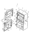
本実施の形態における分離型スロットマシンSは、図2に示すように、大きく分けて、正面側に開口部11を有する筐体1、筐体1内部に着脱自在に設けられる交換ユニット2、筐体1の開口部11を開閉可能に塞ぐ前扉3とから構成されている。そして、この前扉3は、筐体1の開口上部13を開閉可能に塞ぐ上扉30、筐体1の開口下部14を開閉可能に塞ぐ下扉40とに分割されている。
(筐体1)
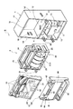
筐体1は、底板15及び側板16及び天板17及び裏板18からなる前面(遊技者と対峙する正面)側に開口する箱体であり、高さ方向略中央部には、二つの側板16,16'の間に水平方向に中板12が設けられている。そして、この中板12の下面には電源ユニット4が設けられ、底板15にはホッパーユニット5が固定されている。
As shown in FIG. 2, the separation type slot machine S according to the present embodiment is roughly divided into a
(Case 1)
The
ここで、電源ユニット4は、中板12の下面に、取り付け板等を介して取り付けられており、特に図示しないが電源装置が内装されていると共に、ホール管理者が種々の設定を行うためのスイッチ等を有している。ホッパーユニット5は、遊技メダルを貯留すると共に払い出すためのものである。
上記電源ユニット4及びホッパーユニット5は、いわゆる「面替え」に際し、必ずしも交換する必要のないものであり、遊技機交換時には設置されたままにしておけるようになっているものである。
また、正面左側の側板16の下部には、前記下扉40を係合させ、回転自在に支持するためのヒンジ19が、上下方向に間隔をおいて二つ設けられている。なお、本実施の形態では上扉30を交換ユニット2の支持体21に取り付ける構成としているが、上扉30を筐体1の側板16に回転自在に取り付ける構成としてもよい。この場合には、側板16の上側にも、上扉30を係合させ回転自在に支持するためのヒンジを設ければよい。
Here, the
The
Further, two hinges 19 for engaging the
ところで、前記中板12の側板16'側正面には、扉位置保持具6が設けられているが、これについては後述する。
(交換ユニット2)
交換ユニット2は、種々の部品を設置あるいは固定するための支持体21と、この支持体21に固定されたリールユニット20及び基板ユニット24とから形成されている。
支持体21は、方形状の金属枠からなり、リールユニット20及び基板ユニット24を筐体内部に着脱自在に固定するとともに、リールユニット20及び基板ユニット24を一体的に取り扱い可能とするものである。なお、支持体21は、他の構成部品(例えば演出用の表示装置)を固定設置可能であってもかまわない。
Incidentally, a
(Exchange unit 2)
The
The
ここで、リールユニット20は、スロットマシンSの主たる遊技装置であって、周囲に複数の図柄を表示した3個の回転リール23と、特に図示しないが、各回転リール23を回転させるための駆動モータを有している。また、前記基板ユニット24には、遊技及びスロットマシンSの作動を制御するための主基板と、各種演出を行うための副基板が内装されている。主基板及び副基板は、CPUを中心に構成され、ROM、RAM、I/O等を備えている。そして、CPUがROMに記憶されたプログラムを読み込むことで、例えば当選役を決定する抽選や回転リール23の回転及び停止を制御する制御装置として機能する。なお、前記副基板は、例えば入賞したことを報知する演出機能を有しており、主基板とは別の基板ユニットとして配置してもよい。
Here, the
前記支持体21の正面左側の縦枠には、前記上扉30を回転自在に係合するためのヒンジ25が、上下方向に間隔をおいて二つ設けられている。
交換ユニット2は、筐体1の中板12の上に乗せ、開口上部13内部に収納されるものである。また、交換ユニット2を開口上部13内に押入したとき、支持体21の正面下部の垂下片21Aが中板12の正面に当接して、奥行き方向の位置決めができるようになっている(図3参照)。そして、筐体1の側板16の内側に設けられたクリップなどの固定装置10によりに固着される。
(上扉30)
上扉30は、交換ユニット2の支持体21に回転自在かつロック可能に形成されている板状の扉であり、図2に示すように、略中央部に前記回転リール23の図柄を正面側から見ることができる図柄表示窓31を有し、周囲に飾り部33を設けてある。そして、前記図柄表示窓31の下方には、種々の表示を行うための表示部32が設けられているものである。
The vertical frame on the left side of the front surface of the
The
(Upper door 30)
The
また、図1に示すように、上扉30の裏面上部の左右には、スピーカ37が取り付けられており、上扉30の裏面において右側端部には、交換ユニット2の支持体21に設けられたヒンジ25に係合可能な上扉係合部38が上下方向に間隔をおいて二つ設けられている。そして、上扉係合部38の対向側端部には、ロック機構39が設けられている。
ここで、前記ロック機構39は、上扉30側に設けられた係止片が、特に図示しないが、筐体1の反ヒンジ側の側板16'内側面に設けられた凸部に係止され、扉を閉めると自動的にロックされ、解錠手段によりロックが解除さるように形成されている。そして、交換ユニット2を筐体1に収納し固定した状態で上扉30を閉めると、筐体1の開口上部13を塞ぐことができ、同時にロックされて開口上部13を施錠することができるものである。さらに、上扉30のロック機構39は扉外側から解錠することができず、下扉40が開いているときにロック解除可能となっている。
As shown in FIG. 1,
Here, in the
(下扉40)
下扉40は、筐体1の開口下部14を塞ぐための、上扉30よりも幅厚の扉であり、筐体1の側板16に回転自在かつロック可能に形成されているものである。
図2に示すように、下扉40の上部は、スロットマシンSを作動させるための操作部41となっており、下扉40の上面は、扉を閉じた時においては、上扉30よりも前側に突出するようになっている。前記操作部41としては、下扉40の上面右端に形成された段部にメダル投入口42、上面左側に設けられたベットスイッチ43及び精算スイッチ、正面側にはスタートスイッチ44及びストップスイッチ45が設けられている。スタートスイッチ44及びストップスイッチ45は、回転リール23の回転を開始及び停止させるためのものである。ベットスイッチ43は、貯留メダルをメダル投入に代えるためのものである。
(Lower door 40)
The
As shown in FIG. 2, the upper portion of the
また、下扉40の下部には、ホッパーユニット5から払い出されたメダルを貯めておくためのメダル皿46が取り付けられており、このメダル皿46に払い出しメダルを排出するメダル排出口が形成されている。前記操作部41とメダル皿46の間には、下パネルユニット90が着脱自在に取り付けられている。なお、下パネルユニット90は、枠体に表示パネルを嵌め込んだものであり、特に図示しないが、枠体の裏面に下扉40に設けられた取り付け溝に係合可能なフック状の係合部を有していて、下扉40の裏面側から係合を解除して取り外せるようになっている。
さらに、図1に示すように、下扉40の裏面側には、前記メダル投入口42から投入されたメダルを誘導しながらメダルの真贋を判断するためのメダルセレクター47が設けられている。また、下扉40の裏面において右側端部には、前記ヒンジ19と係合可能な下扉係合部48が上下方向に間隔をおいて二つ設けられており、下扉係合部48の対向側端部には、ロック機構49が設けられている。このロック機構49は、上扉30のロック機構39と基本的構造は同じであるが、下扉40の正面側側端部に設けられた鍵穴に所定の鍵(解除手段)を差し込んで回すと、ロックが解除されるようになっている。
A
Further, as shown in FIG. 1, a
なお、下扉40の裏面において左側上端部には、扉位置保持具6が設けられているが、これについては後述する。
(スロットマシンSの交換)
以上のように形成されたスロットマシンSは、いわゆる面替えの際には、前扉3を開けて固定装置10を解除し、交換ユニット2を上扉30ごと筐体1から取り外し、下扉40から下パネルユニット90を取り外す。それから、新しい交換ユニット2と上扉30を筐体1に取り付け固定し、下パネルユニット90を下扉40に取り付ける。こうして、筐体1とその内部に設置されているホッパーユニット5や電源ユニット4はそのままに、上扉30と下パネルユニット90の交換によりスロットマシンの正面デザインを新たなものとすることができ、交換ユニット2の交換によりリールユニット20及び基板ユニット24を新たな機種に対応したものに変更することができる。
Note that a
(Replacement of slot machine S)
The slot machine S formed as described above opens the
(扉位置保持具6)
次に、扉位置保持具6について詳述する。
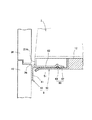
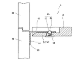
扉位置保持具6は、前扉3の上下方向の位置変化を規制するとともに、前扉3の閉じ位置の前後方向の位置決めをするためのものであり、特に、下扉40の反ヒンジ19側のへたりを防止し、上扉30と下扉40との隙間が開かないようにするためのものである。そして、扉位置保持具6は、筐体1に設けられた受け部50と、下扉40に設けられた下扉差し込み部材60とにより構成される。
受け部50は、図2に示すように、中板12の正面側右端部に形成された切欠き部に嵌め込まれた、断面略L字型の薄板部材であり、図3に示すように、正面側に張り出す支持板51を有している。そして、支持板51の上面には、上方に突出する円錐形又は半球形の凸部52が形成されている。これは、後述する下扉差し込み部材60に設けられた凹部63とともに、係合部80を構成するものである。また、この凸部52は、図4に示すように、支持板51に略U字形のスリットを穿設することにより形成されるU字形の舌片51aの先端側に設けられており、上下方向から力が加えられると舌片51aが撓んで、凸部52が上下に移動可能となっている。
(Door position holder 6)
Next, the
The
As shown in FIG. 2, the receiving
さらに、図3及び図4に示すように、前記支持板51の正面側端部は、下側に向かって湾曲して形成されている。これは、後述する差し込み片62の差し込みをスムーズに行わせるためである。
なお、支持体21の垂下片21Aには、受け部50の設置位置に対応する部分に切欠き部26が形成されているので、交換ユニット2を収納したとき、受け部50が垂下片21Aに隠れてしまうことはない。
下扉差し込み部材60は、図1及び図3に示すように、下扉40の裏側であって下扉係合部48の対向側下端部に設けられたL字型の金具であり、取り付け片61と差し込み片62を有している。取り付け片61は、下扉差し込み部材60を下扉40に固定するためのものであり、差し込み片62は、下扉40を閉じたとき、受け部50の支持板51の上側と交換ユニット2の支持体底面との間に差し込まれるものであり、支持板51の横幅よりも若干短い横幅を有している。
Further, as shown in FIGS. 3 and 4, the front-side end portion of the
The hanging
As shown in FIGS. 1 and 3, the lower
また、前記差し込み片62の下面には、図3に示すように、下扉40を閉じたときに支持板51の凸部52と係合可能な凹部63が形成されている。この凹部63は、図4に示すように、差し込み片62の幅方向に亘って設けられた溝であるが、凹部63としてはこのような形状に限られず、円錐形の凹部や丸孔であってもよい。
なお、前記係合部80としては、受け部50に凹部を設け、下扉差し込み部材60に凸部を設けてもよい。
以上のような構成を有する扉位置保持具6は、前扉3を閉じた状態では、図3に示すように、差し込み片62受け部50の支持板51上に差し込まれており、かつ差し込み片62の下面と支持板51の上面が当接している。さらに、凸部52と凹部63が係合しあい、差し込み片62は、下方向及び前後方向の移動を規制されている。この状態では、下扉40に上方からの力がかかっても、差し込み片62を支持板51が下方から支持するので、下扉40が下方に移動することはない。また、扉位置保持具6は、反ヒンジ側に設けられているので、下扉40の反ヒンジ側が自重により下方に下がるのを防止することができる。このように、扉位置保持具6により、下扉40の上下方向の位置が保持されると、下扉40を長年使用してもへたることなく、交換した上扉30との接合部分に隙間が生じることもない。
Further, as shown in FIG. 3, a
As the engaging
When the
また、下扉40を開くと、差し込み片62も受け部50から離れる方向に移動するが、凸部52は上下動可能な舌片51aに設けられているので、ある程度の力がかかると差し込み片62の下面に押し下げられて、凸部52と凹部63の係合が外れる。そして、下扉40を閉じるときには、上記と同様に凸部52はいったん差し込み片62の下面に押し下げられた後、凹部63と係合する。このように、下扉差し込み部材60と受け部50に、凸部52及び凹部63からなる係合部80を設けてあると、下扉40の前後方向の移動も規制することができ、非施錠状態であっても確実に扉を閉めることができると共に、係合部80の係合のクリック感で扉が適位置まで閉まったことを知ることができる。
When the
なお、下扉差し込み部材60は、下扉40に後付けするようになっているが、これは、既存のスロットマシンに取り付け可能とするためであって、差し込み片62を直接下扉40の裏面側、例えば下扉40の扉枠裏面に形成してもよいものである。
ところで、係合部80は、図5に示すように形成してもよい。すなわち、受け部50の支持板51を、中板12の正面側に切り欠き段部を設けて中板12に形成するとともに、支持板51の上面から突出する突出ストッパー57を設け、一方差し込み片62には前記突出ストッパー57と係合可能な係合孔64を設けたものである。ここで、前記突出ストッパー57は、支持板51に設けられた収納孔56内にバネで固定され先端が球状に形成された短尺のピンであり、常時上方に付勢されて、支持板51から突出しているが、差し込み片62が差し込まれると差し込み片62の下面に押されて収納孔56内に陥没し、さらに差し込み片62が係合孔64と収納孔56の一致する位置まで差し込まれると、バネの付勢力で上方に突出して、係合孔64と係合するものである。
Note that the lower
Incidentally, the engaging
係合部80の形態は、上述した形態に限られず、凹部と凸部が係合して差し込み片62の前後方向の移動を規制可能なもであれば、どのような形態であってもかまわない。
(扉位置保持具6の他の例)
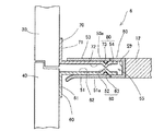
ここで、扉位置保持具6の他の実施の形態を述べる。
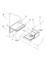
まず、図6に示すように、扉位置保持具6として、上扉30に上扉差し込み部材70を設けてもよい。
この場合、受け部50は、図6に示すように、中板12の正面側右端部に形成された切欠き部に嵌め込まれ正面側に開口する断面略コ字型の薄板部材とし、下側の支持板51及び上側の支持板53の間に空間部55が形成されている。そして、支持板51の上面及び支持板53の下面には、前記空間部55内に突出する凸部52,54がそれぞれ形成されている。なお、凸部52,54は、図4に示したのと同様の構成により、上下に移動可能である。また、前記支持板53の上面は、中板12と面一に形成されているので、交換ユニット2の着脱の際に邪魔にならない。
The form of the engaging
(Other examples of door position holder 6)
Here, another embodiment of the
First, as shown in FIG. 6, an upper
In this case, as shown in FIG. 6, the receiving
上扉差し込み部材70は、特に図示しないが、上扉30の裏側であって上扉係合部38の対向側上端部に設けられ、図6示すように、前記下扉差し込み部材60と同様に、上扉30に固定される取り付け片71と、支持板53の凸部54と係合可能な凹部73を有する差し込み片72を有している。
このように形成した場合には、前扉3を閉めたとき、差し込み片62,72が共に空間部55内に係止され、上扉30の下端部と下扉40の上端部との間隙が、常に一定に保たれるという利点がある。
さらに、上記の場合、図7に示すように、受け部50を中板12の正面に、開口部11の横幅に亘って取り付け、前記下扉差し込み部60及び前記上扉差し込み部材70を前記受け部50に対応させて長尺に形成してもよい。このように形成した場合には、上扉30と下扉40の接合部の隙間から棒状の異物を挿入しようとしても、下扉差し込み部60が開口下部14への進入を、上扉差し込み部材70が開口上部13への進入を、受け部50の奥側の立面59(図6参照)が奥行き方向の進入をそれぞれ阻止し、異物を完全にシャットアウトすることができるので、ゴト防止に効果的である。
Although not shown in particular, the upper
In this case, when the
Further, in the above case, as shown in FIG. 7, the receiving
なお、下扉差し込み部材60及び上扉差し込み部材70を、前扉3の反ヒンジ側のみに設けた場合でも、受け部50を図7のように形成することにより、上扉30と下扉40の接合部の奥側には立面59が位置しているので、異物の進入を阻止することが可能である。
(第二の実施の形態)
第二の実施の形態は、前扉3が上下に分割されていないスロットマシンに係る。
本実施の形態においては、スロットマシンS'は、図8に示すように、前扉3を、前扉枠140と、この前扉枠140に着脱自在に取り付けられた上パネルユニット130及び下パネルユニット90とから形成し、遊技台交換の際には、上パネルユニット130及び下パネルユニット90のみ取り替えて、前扉枠140は筐体1に取り付けたままにしておくことができるものである。なお、スロットマシンS'の基本的な構成は、第一の実施の形態と同様であるので、重複する部分は省略し、本実施の形態の特徴点のみ述べる。
Even when the lower
(Second embodiment)
The second embodiment relates to a slot machine in which the
In the present embodiment, as shown in FIG. 8, the slot machine S ′ includes a
前記前扉枠140は、筐体1にヒンジ19を介して取り付けられる前扉3の骨格部分であって、上部開口141及び下部開口142を有し、上部開口141及び下部開口142の間にはスタートスイッチ44等の操作手段が設けられた操作部41が形成されている。
上部開口141は、上パネルユニット130を正面側から取り付けることにより塞がれる開口部であって、上部開口141を形成する周囲の枠には、特に図示しないが、上パネルユニット130を着脱自在に取り付けるための係合部が設けられている。前記下部開口142は、下パネルユニット90を正面側から取り付けることにより塞がれる開口部であって、内部には、下パネルを照明するための蛍光ランプが設置されている。また、下部開口142の下方には、メダル皿46が形成されている。
The
The
上パネルユニット130は、前記前扉枠140の上部開口141に取り付ける板状のパネルであって、図柄表示窓31、表示部32、飾り部33を有している。また、上パネルユニット130の裏面には、特に図示しないが、上部開口141の係合部と係合可能な係合部が設けられている。
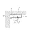
そして、スロットマシンS'においては、筐体1の天板17下面と、前扉枠140の反ヒンジ側裏面に、扉位置保持具6が設けられている。すなわち、図9に示すように、前扉枠140の裏面上部に張り出し片100を設け、天板17の下面には受け部50を設ける。ここで、図示した例では、受け部50は、支持板51及び取り付け板58を有する断面略コ字型の薄板部材であるが、取り付け板58が背面方向に延設されていてもよいし、支持板51が天板17の下面から吊り下げられているものでもよい。
The upper panel unit 130 is a plate-like panel that is attached to the
In the slot machine S ′, the
このように形成することにより、前扉枠140の反ヒンジ側が長年の使用により下方に下がるのを防止し、天板17と前扉3の上端部との間に隙間ができないようにすることができる。
なお、本発明は、スロットマシン以外の遊技機にも応用できるものである。
By forming in this way, it is possible to prevent the anti-hinge side of the
The present invention can also be applied to gaming machines other than slot machines.
S 分離型スロットマシン
1 筐体 2 交換ユニット
3 前扉 4 電源ユニット
5 ホッパーユニット 6 扉位置保持具
10 固定装置 11 開口部
12 中板 13 開口上部
14 開口下部 15 底板
16 側板 17 天板
18 裏板 19 ヒンジ
20 リールユニット(遊技装置) 21 支持体
23 回転リール 24 基板ユニット(制御装置)
25 ヒンジ 26 切欠き部
30 上扉 31 図柄表示窓
32 表示部 33 飾り部
37 スピーカ 38 上扉係合部
39 ロック機構
40 下扉 41 操作部
42 メダル投入口 43 ベットスイッチ
44 スタートスイッチ 45 ストップスイッチ
46 メダル皿 47 メダルセレクター
48 下扉係合部 49 ロック機構
50 受け部 51 支持板
52 凸部 53 支持板
54 凸部 55 空間部
56 収納孔 57 突出ストッパー
58 取り付け片 59 立面
60 下扉差し込み部材 61 取り付け片
62 差し込み片 63 凹部
64 係合孔
70 上扉差し込み部材 71 取り付け片
72 差し込み片 73 凹部
80 係合部 90 下パネルユニット
100 差し込み片 101 凹部
130 上パネルユニット
140 前扉枠 141 上部開口
142 下部開口
S
10
12 Middle plate 13 Upper opening
14
16
18
20 reel unit (game machine) 21 support
23
25
30
32
37
39 Locking mechanism
40
42
44
46
48 Lower
50
52
54
56
58
60 Lower
62
64 engagement hole
70 Upper
72
80
100
130 Upper panel unit
140
142 Bottom opening
Claims (4)
筐体内部に設置される遊技装置及び遊技装置の作動を制御するための制御装置と、
前記筐体の側方にヒンジを介して開閉自在に取り付けられ、前記開口部を塞ぐ前扉とを少なくとも有し、
少なくとも前記制御装置を筐体に対して着脱自在に形成した遊技機において、
前記前扉の裏面の少なくとも反ヒンジ側に、前記前扉を閉めたときに筐体の背面側に向かって略水平に張り出す差し込み片を設け、
前記筐体の正面に、前記前扉を閉めたときに前記差し込み片を下側から支持する受け部を設けたことを特徴とする遊技機。 A housing having an opening on the front side;
A gaming device installed inside the housing and a control device for controlling the operation of the gaming device;
At least a front door that is attached to a side of the housing so as to be freely opened and closed via a hinge and closes the opening,
In a gaming machine in which at least the control device is formed detachably with respect to the housing,
On at least the anti-hinge side of the back surface of the front door, an insertion piece is provided that projects substantially horizontally toward the back side of the housing when the front door is closed,
A gaming machine, wherein a receiving portion is provided on a front surface of the housing to support the insertion piece from below when the front door is closed.
前記前扉として、前記開口上部を塞ぐ上扉及び前記筐体の開口下部を塞ぐ下扉を設け、
前記交換ユニット及び前記上扉を、前記筐体から着脱自在に形成するとともに、
少なくとも前記下扉の裏面上部に、前記差し込み片を設けたことを特徴とする請求項1記載の遊技機。 An exchange unit in which at least the gaming device and the control device are mounted on a support that supports them is formed so as to be housed in the upper opening of the housing,
As the front door, an upper door that closes the upper opening and a lower door that closes the lower opening of the housing are provided,
While forming the exchange unit and the upper door detachable from the housing,
The gaming machine according to claim 1, wherein the insertion piece is provided at least on the upper surface of the lower surface of the lower door.
Protrusions provided on either the insertion piece or the receiving part, and provided on the receiving part or the insertion piece not provided with the protruding part, and can be engaged with the protrusion when the door is closed. The gaming machine according to any one of claims 1 to 3, further comprising an engaging portion including a concave portion.
Priority Applications (1)
| Application Number | Priority Date | Filing Date | Title |
|---|---|---|---|
| JP2004121149A JP2005296542A (en) | 2004-04-16 | 2004-04-16 | Game machine |
Applications Claiming Priority (1)
| Application Number | Priority Date | Filing Date | Title |
|---|---|---|---|
| JP2004121149A JP2005296542A (en) | 2004-04-16 | 2004-04-16 | Game machine |
Related Child Applications (1)
| Application Number | Title | Priority Date | Filing Date |
|---|---|---|---|
| JP2008305872A Division JP2009045484A (en) | 2008-12-01 | 2008-12-01 | Game machine |
Publications (1)
| Publication Number | Publication Date |
|---|---|
| JP2005296542A true JP2005296542A (en) | 2005-10-27 |
Family
ID=35328781
Family Applications (1)
| Application Number | Title | Priority Date | Filing Date |
|---|---|---|---|
| JP2004121149A Pending JP2005296542A (en) | 2004-04-16 | 2004-04-16 | Game machine |
Country Status (1)
| Country | Link |
|---|---|
| JP (1) | JP2005296542A (en) |
Cited By (2)
| Publication number | Priority date | Publication date | Assignee | Title |
|---|---|---|---|---|
| JP2007325885A (en) * | 2006-06-09 | 2007-12-20 | Aruze Corp | Game machine |
| JP2009219686A (en) * | 2008-03-17 | 2009-10-01 | Okumura Yu-Ki Co Ltd | Pachinko game machine |
-
2004
- 2004-04-16 JP JP2004121149A patent/JP2005296542A/en active Pending
Cited By (2)
| Publication number | Priority date | Publication date | Assignee | Title |
|---|---|---|---|---|
| JP2007325885A (en) * | 2006-06-09 | 2007-12-20 | Aruze Corp | Game machine |
| JP2009219686A (en) * | 2008-03-17 | 2009-10-01 | Okumura Yu-Ki Co Ltd | Pachinko game machine |
Similar Documents
| Publication | Publication Date | Title |
|---|---|---|
| JP2013070810A (en) | Game machine | |
| JP2005152682A (en) | Slot machine | |
| JP4726819B2 (en) | Amusement stand | |
| JP3699429B2 (en) | Separate slot machine | |
| JP4307279B2 (en) | Game machine | |
| JP2005296542A (en) | Game machine | |
| JP4227945B2 (en) | Game machine | |
| JP2009045484A (en) | Game machine | |
| JP4271633B2 (en) | Game machine | |
| JP4271628B2 (en) | Game machine | |
| JP2005296029A (en) | Game machine | |
| JP4496151B2 (en) | Game machine | |
| JP4283207B2 (en) | Game machine | |
| JP2005143678A (en) | Game machine | |
| JP4335165B2 (en) | Game machine | |
| JP4229454B2 (en) | Separate type gaming machine | |
| JP2007252490A (en) | Lock device and game machine | |
| JP4402024B2 (en) | Game machine | |
| JP4132935B2 (en) | Slot machine | |
| JP4402028B2 (en) | Game machine | |
| JP4395092B2 (en) | Game machine | |
| JP4615452B2 (en) | Game machine | |
| JP4496152B2 (en) | Game machine | |
| JP2005160981A (en) | Hinge for front door of game machine | |
| JP2006122185A (en) | Separate type game machine |
Legal Events
| Date | Code | Title | Description |
|---|---|---|---|
| A977 | Report on retrieval |
Free format text: JAPANESE INTERMEDIATE CODE: A971007 Effective date: 20081001 |
|
| A131 | Notification of reasons for refusal |
Free format text: JAPANESE INTERMEDIATE CODE: A131 Effective date: 20081009 |
|
| A521 | Written amendment |
Free format text: JAPANESE INTERMEDIATE CODE: A523 Effective date: 20081201 |
|
| A02 | Decision of refusal |
Free format text: JAPANESE INTERMEDIATE CODE: A02 Effective date: 20090319 |