JP2005296533A - dishwasher - Google Patents
dishwasher Download PDFInfo
- Publication number
- JP2005296533A JP2005296533A JP2004120990A JP2004120990A JP2005296533A JP 2005296533 A JP2005296533 A JP 2005296533A JP 2004120990 A JP2004120990 A JP 2004120990A JP 2004120990 A JP2004120990 A JP 2004120990A JP 2005296533 A JP2005296533 A JP 2005296533A
- Authority
- JP
- Japan
- Prior art keywords
- cleaning
- washing
- water
- cleaning tank
- pump
- Prior art date
- Legal status (The legal status is an assumption and is not a legal conclusion. Google has not performed a legal analysis and makes no representation as to the accuracy of the status listed.)
- Granted
Links
Images
Classifications
-
- Y—GENERAL TAGGING OF NEW TECHNOLOGICAL DEVELOPMENTS; GENERAL TAGGING OF CROSS-SECTIONAL TECHNOLOGIES SPANNING OVER SEVERAL SECTIONS OF THE IPC; TECHNICAL SUBJECTS COVERED BY FORMER USPC CROSS-REFERENCE ART COLLECTIONS [XRACs] AND DIGESTS
- Y02—TECHNOLOGIES OR APPLICATIONS FOR MITIGATION OR ADAPTATION AGAINST CLIMATE CHANGE
- Y02B—CLIMATE CHANGE MITIGATION TECHNOLOGIES RELATED TO BUILDINGS, e.g. HOUSING, HOUSE APPLIANCES OR RELATED END-USER APPLICATIONS
- Y02B40/00—Technologies aiming at improving the efficiency of home appliances, e.g. induction cooking or efficient technologies for refrigerators, freezers or dish washers
Landscapes
- Washing And Drying Of Tableware (AREA)
Abstract
Description
本発明は、使用水量を少なくした食器洗い機に関する。 The present invention relates to a dishwasher that uses less water.
低水位、少水量で食器容量が大きい食器洗い機に関するものは特開2002−165745公報等で示されている。 Japanese Patent Application Laid-Open No. 2002-165745 discloses a dishwasher having a low water level, a small amount of water, and a large tableware capacity.
食器洗い機において、洗浄水の使用水量を少なくすると、洗浄ポンプで加圧された洗浄水は管路を通って、上ノズル及び下ノズルから噴出し食器に当たって下方に落下する。下方に落下した洗浄水は上側洗浄槽底部とそれより一段と低い位置にある下側洗浄槽底部に落下する。面積については上側洗浄槽底部の方が大きいので、この部分に落下した洗浄水が洗浄ポンプの吸込み側の残菜フイルター部に迅速に集めないと吸込み側に洗浄水の供給が間に合わなくなりエアーを吸込みエアーロックを生じてポンプ性能が低下するため洗浄率が悪くなる。このため、洗浄水の戻りをよくエアーロックを防止した食器洗い機を提供することを目的とする。 In the dishwasher, when the amount of washing water used is reduced, the washing water pressurized by the washing pump is discharged from the upper nozzle and the lower nozzle through the pipe and hits the tableware and falls downward. The washing water dropped downward falls to the upper washing tank bottom and the lower washing tank bottom located at a lower position. The area at the bottom of the upper cleaning tank is larger in area, so the cleaning water that falls on this part will not be collected quickly in the side filter section on the suction side of the cleaning pump, and the supply of cleaning water will not be in time to suck in air. Since the air lock is generated and the pump performance is lowered, the cleaning rate is deteriorated. For this reason, it aims at providing the dishwasher which prevented the air lock | rock well for the return of washing water.
上記目的を達成するために本発明の特徴とするところは、食器を収納する食器かごと、該食器かごを載置する洗浄槽と、該洗浄槽内に洗浄水を供給する洗浄水供給手段と、洗浄水を圧送する洗浄ポンプと、該洗浄ポンプで圧送された洗浄水を噴射する噴射口を有する洗浄ノズルと、洗浄水を加熱するヒータと、食器を乾燥する風を送るファンと、洗浄水を洗浄槽より排水する排水手段と、前記洗浄水供給手段、洗浄ポンプ、加熱手段、排水手段を制御して洗い工程、すすぎ工程、乾燥工程等の一連の洗浄工程を行う制御手段とを備える食器洗い機において、前記洗浄槽の底部は、上側洗浄槽底部と、該上側洗浄槽底部より下方に位置した下側洗浄槽底部より構成され、前記上側洗浄槽底部は前記下側洗浄槽底部に向かって下るように傾斜させたことにある。 In order to achieve the above object, the present invention is characterized by a tableware basket for storing tableware, a cleaning tank for placing the tableware basket, and a cleaning water supply means for supplying cleaning water into the cleaning tank. A cleaning pump for pumping the cleaning water, a cleaning nozzle having an injection port for spraying the cleaning water pumped by the cleaning pump, a heater for heating the cleaning water, a fan for sending wind for drying the dishes, and the cleaning water Dishwasher comprising drainage means for draining water from the washing tank and control means for controlling the washing water supply means, washing pump, heating means, drainage means to perform a series of washing steps such as a washing step, a rinsing step, and a drying step In the machine, the bottom of the washing tank is composed of an upper washing tank bottom and a lower washing tank bottom located below the upper washing tank bottom, and the upper washing tank bottom is directed toward the lower washing tank bottom. Tilt down Lies in the fact.
本発明によれば、使用水量が少なくても洗浄水の吸込み側の残菜フイルター部にノズルから噴出した洗浄水を迅速に回収出来るのでエアーロックによる洗浄ポンプの性能が低下させずに洗浄を行うことが出来る。 According to the present invention, even if the amount of water used is small, the cleaning water ejected from the nozzle to the side filter section on the suction side of the cleaning water can be quickly collected, so that the performance of the cleaning pump by the air lock is not degraded. I can do it.
本発明の実施形態の一例について、添付の図面に基づいて説明する。 An example of an embodiment of the present invention will be described with reference to the accompanying drawings.
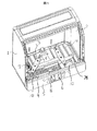
図1は本発明の実施例である食器洗い機のドア部分を除去したときの正面図を示す。食器洗い機は、本体外枠1の内部に洗浄槽2が備わる。本体外枠1は、ステンレス等の鋼板で、洗浄槽2は耐熱性の合成樹脂で形成されており内側はステンレスの鋼板が張られている。また、本体外枠1の前面側には、図示していないが、洗浄槽2の前側に設けた開口部を開け閉めする上側扉体および下側扉体が備わる。本体外枠1は、ステンレス等の鋼板で、洗浄槽2は耐熱性の合成樹脂で形成されている。
FIG. 1 shows a front view when the door portion of the dishwasher according to the embodiment of the present invention is removed. The dishwasher includes a
本体外枠1の前面側には、図示していないが、洗浄槽2の前側に設けた開口部を開け閉めする上側扉体および下側扉体が備わる。洗浄槽2の下部には、洗浄水を噴射するところの回転自在なる洗浄ノズル3が備わる。洗浄ノズル3は噴射孔4を有し、この噴射孔4より噴射する洗浄水によって、洗浄槽2に収納する食器が洗浄される。
Although not shown, the front side of the main body outer frame 1 is provided with an upper door body and a lower door body that open and close an opening provided on the front side of the
洗浄ノズル3は、噴射孔4から噴射する洗浄水の反動で回転する。洗浄槽2には、洗浄ノズル3の上側に食器かご(図示せず)が備えられ、この食器かごに食器が収納される。
The
本体外枠1の前側下部には、フロントパネル5が設けられる。このフロントパネル5の内側には、食器洗い機の運転を操作したり、制御したりする各種の制御装置が備わる。
A
洗浄槽2の下方である底には、洗浄水が溜まる下側洗浄槽底部6が設けられる。この下側洗浄槽底部6は、左側から手前側に亘ってL形の窪みになっている。洗浄槽2の底は、下側洗浄槽底部6のところが窪みになって低く、前記洗浄ノズル3が設けられる奥底側のところは上側洗浄槽底部24で一段と高くした構成になっている。
At the bottom below the
上側洗浄槽底部24の上面にはリブ11が下側洗浄槽底部6に向かって複数個配置されている。このリブ11は洗浄水が落下した時出来るだけ最短距離で下側洗浄槽底部6側に流れるようにするもので、特に左側面の下側洗浄槽底部6に流れると残菜フイルター30までの距離が長くなりその分無駄水となるのでリブ11も他のリブより高くする方がより効果がある。このリブの本数については傾斜が大きいものは間隔を大きくし、傾斜が緩いものは間隔を狭く、且つ、リブの高さも高くした方が効率よく洗浄水を下側洗浄槽底部6に導くことが出来る。また、下側洗浄槽底部6の残菜フイルター30から距離の遠い部分には、左側の部位に取り外し自在なる除菌カセット7が備わり残菜が少ないので除菌カセット7のまわりに残菜が滞留しにくい位置としている。
A plurality of ribs 11 are arranged on the upper surface of the upper
下側洗浄槽底部6の手前側には、右側部位を除いて加熱ヒータ8が備わる。加熱ヒータ8は、ヒータカバー9で上側から覆われる。ヒータカバー9は、多数の通気穴10を有する。
A
加熱ヒータ8は、洗浄槽2の底部面積のかなりの部分を占める大きな部品である。しかも、電源回路側と接続しなければならないので手前側の下側洗浄槽底部6は、加熱ヒータ8が収まるようにスペースを大きくとっており、且つ洗浄槽2の開口部側であるので、電源回路側との接続作業もし易いのである。
The
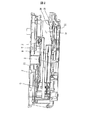
図2は図1の下側洗浄槽底部6の手前側部分の断面を示す。下側洗浄槽底部6の手前側の右側部位は、洗浄水が流れ出る流出部位20になる。下側洗浄槽底部6は、流出部位20に向け僅かに傾斜する下り勾配になっている。水量を早く確保したいときはこの勾配を大きくして戻り水を確保する。この下り勾配により、流出部位20に洗浄水を流れ易くしている。
FIG. 2 shows a cross section of the front side portion of the lower
流出部位20は、ほぼ中央に洗浄水が流れ出る流出口21を有する。流出部位20の全周は、流出口21に向かって下がるように傾斜している。流出口21は数ミリ角の格子22を有し、比較的大きな異物の流入防止をしている。流出口21の下方は、吸い込み通水ダクト(図示せず)を介して洗浄ポンプ(図示せず)の吸い込み側に連通している。洗浄ポンプの吐出側は、ノズル通水ダクト23に連通する。洗浄ノズル3には、ノズル通水ダクト23を介して洗浄ポンプにより加圧された高圧の洗浄水が供給され、噴射孔4から勢い良く洗浄水が噴射され食器を洗浄する。また、残菜フイルター30は、多数の濾目穴を有するステンレスの鋼板で形成する。板厚が、0.5mm程度の薄いステンレスの鋼板を用いる。濾目穴の直径は1.5mm程度の小さな穴、濾目穴の間隔は、2mm程度の小さなピッチで多数く形成される。濾目穴は、プレス加工によって形成する。残菜フイルター30は、全体の形状が矩形で、ほぼ中央に落ち込み凹部31を有する。落ち込み凹部31は、縦/横の巾が50mm程度の矩形形状を有し、深さが15mm程度である。
The
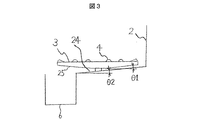
図3はノズルと上側洗浄槽底部24の関係を示した略断面図を示す。洗浄ノズル3は上側洗浄槽底部24の上面部に取付けられている。上側洗浄槽底部24は水平面との角度はθ1となっており洗浄ノズル3は下面部25が上側に傾斜しており水平面との角度はθ2となっている。ここで、θ1≧θ2であれば洗浄ノズル3が上側洗浄槽底部24にぶつかることなく傾斜をとることが出来る。すなわち、上側洗浄槽底部24の上面に傾斜を大きくとろうとすると洗浄ノズル3の下面部25を上方に傾斜させることが必要である。本機では1〜10度の範囲としている。
FIG. 3 is a schematic cross-sectional view showing the relationship between the nozzle and the upper
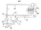
図4は洗浄水が循環する循環経路の略図を示す。40は圧送手段として洗浄ポンプである。洗浄ポンプ40で加圧された洗浄水は水流切替え弁41により下側循環経路42と上側循環経路43に自在に切替えることが出来る。上側循環経路43は背面部経路43aとから成立っている。水使用量が極端に少ない時は循環経路内に滞留する洗浄水も無視できないのでこの時は下側循環経路42と上側循環経路43を交互に使用して循環経路内の洗浄水を少なくする。
FIG. 4 shows a schematic diagram of the circulation path through which the wash water circulates.
下洗浄ノズル4aあるいは上洗浄ノズル4bから噴出した洗浄水は食器かご44に入った食器45を洗浄して上側洗浄槽底部24の上面に落下する。上側洗浄槽底部24に落下した洗浄水は傾斜が無いとかなりの洗浄水が滞留するため、できるだけ大きくして下側洗浄槽底部6に流れるようにすることが必要である。傾斜角度の最低値は洗浄水が表面張力で維持できない角度以上が好ましい。
The washing water sprayed from the
下側洗浄槽底部6に流れた洗浄水は残菜フイルター30を通って流出口21から下側水溜槽46を通って洗浄ポンプ40の吸込み側47から吸い上げられる。この時、下側水溜槽46の下面は洗浄ポンプ40の吸込み側47に向かって緩やかな傾斜とすることにより効率よく洗浄ポンプ40の吸込み側47に洗浄水を供給できる。
The washing water flowing to the bottom
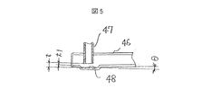
また、吸込み側47の水位が低くなるとエアーを巻込み易いので下側水溜槽46の上面にそのまま洗浄ポンプ40の吸込み側の配管を同じ高さにしないでそれより低くすることにより水位が多少低くなってもエアーの吸込みがなく安定して運転することが出来る。このとき、洗浄ポンプ40の性能を低下させないように内径断面積に対して側面部の開口面積を大きくしている。これにより、吸込み時の側面の流体抵抗による影響を無くしている。すなわち、πd2≦tπdの関係としている。
In addition, since the air is likely to be entrained when the water level on the
図5は本発明の吸込み側47部の部分拡大図を示す。吸込み側47の底部は凹部48に示すように(t−t1)の長さ分下側に突き出ている。これにより、吸込みの水位を(t−t1)分低くすることが出来る。
FIG. 5 shows a partially enlarged view of the
洗浄水の使用量は本機では約3050cc使用しており、上洗浄ノズル4bのみ噴射した場合の各部の水量は実測では1140ccで、各部の水量は上側循環経路43部で46.2cc、背面部経路43a部は61.8cc、水流切換え弁41部は89.1cc、上洗浄ノズル4b部は3個で31.5cc、洗浄ポンプ40部は144cc、下側水溜部47部は350ccで合計722.6ccとなり洗浄ノズルから噴出した滞留分は417.4ccとなる。また、下洗浄ノズル4aのみ噴射した場合の各部の水量は実測では1140ccで、1920ccで、各部の水量は下側循環経路42部で80.6cc、水流切換え弁41部は89.1cc、下洗浄ノズル4a部は2個で88cc、洗浄ポンプ40部は144cc、下側水溜部47部は350ccで合計751.7ccとなり洗浄ノズルから噴出した滞留分は1168.3ccとなり洗浄水量の38.3%を占め滞留分の影響は下洗浄ノズル4aの方が大きい。このため、本発明はこの滞留分を洗浄ポンプ吸込み側に迅速に戻すため洗浄ノズルから噴出した洗浄水が落下する上側洗浄槽底部において傾斜をつけることにより下側洗浄槽底部に洗浄水が流れるようにするとともにより効率よく洗浄ポンプの吸込み側の残菜フイルターに近い下側洗浄槽底部に洗浄水が流れるようにするため上側洗浄槽底部の上面にリブを設けて吸込み側から遠い部分に流れないようにした。また、洗浄水が溜まる部分、上側洗浄槽底部の上面、下側洗浄槽底部、下側水溜部については洗浄水が流れる方向に傾斜を設けて水量を迅速に確保することにより使用水量の少ない食器洗い機を洗浄ポンプのエアーロックなしに運転するようにした。
The amount of water used for washing is about 3050 cc in this machine. When only the upper washing nozzle 4b is sprayed, the amount of water in each part is 1140 cc in actual measurement, the amount of water in each part is 46.2 cc in the
1…外枠、2…洗浄槽、3…洗浄ノズル、4…噴射孔、4a…下洗浄ノズル、4b…上洗浄ノズル、5…フロントパネル、6…下側洗浄槽底部、7…除菌カセット、8…加熱ヒータ、9…ヒータカバー、10…通気穴、20…流出部位、21…流入口、22…格子、23…ノズル通水ダクト、24…上側洗浄槽底部、25…下面部、30…残菜フイルター、31…落ち込み凹部、40…洗浄ポンプ、41…水流切換え弁、42…下側循環経路、43…上側循環経路、43a…背面部経路、44…食器かご、45…食器、46…下側水溜部、47…吸込み側、48…凹部
DESCRIPTION OF SYMBOLS 1 ... Outer frame, 2 ... Cleaning tank, 3 ... Cleaning nozzle, 4 ... Injection hole, 4a ... Lower cleaning nozzle, 4b ... Upper cleaning nozzle, 5 ... Front panel, 6 ... Lower side cleaning tank bottom part, 7 ...
Claims (5)
前記洗浄槽の底部は、上側洗浄槽底部と、該上側洗浄槽底部より下方に位置した下側洗浄槽底部より構成され、前記上側洗浄槽底部は前記下側洗浄槽底部に向かって下るように傾斜させたことを特徴とする食器洗い機。 Tableware basket for storing tableware, cleaning tank for placing the tableware basket, cleaning water supply means for supplying cleaning water into the cleaning tank, cleaning pump for pumping cleaning water, and pumping by the cleaning pump A cleaning nozzle having an ejection port for injecting the cleaning water, a heater for heating the cleaning water, a fan for sending wind for drying the dishes, a draining means for draining the cleaning water from the cleaning tank, and the cleaning water supply means, In a dishwasher comprising a control means for controlling a washing pump, a heating means, a draining means to perform a series of washing steps such as a washing step, a rinsing step, and a drying step,
The bottom of the cleaning tank is composed of an upper cleaning tank bottom and a lower cleaning tank bottom located below the upper cleaning tank bottom, and the upper cleaning tank bottom is lowered toward the lower cleaning tank bottom. A dishwasher characterized by being inclined.
前記下側洗浄槽底部に残菜フイルターを設け、前記上側洗浄槽底部には前記残菜フイルターに向かって延びたリブを設けたことを特徴とする食器洗い機。 In claim 1,
A dishwasher, wherein a bottom filter is provided at the bottom of the lower washing tank, and a rib extending toward the leftover filter is provided at the bottom of the upper washing tank.
前記洗浄ノズルの下面側を外周側から回転中心に向かって下るように傾斜させ、前記上側洗浄槽底部の傾斜角度は、前記洗浄ノズル下面側の傾斜角度とほぼ同一としたことを特徴とする食器洗い機。 In claim 1,
Dishwashing characterized in that the lower surface side of the washing nozzle is inclined so as to descend from the outer peripheral side toward the center of rotation, and the inclination angle of the bottom of the upper cleaning tank is substantially the same as the inclination angle of the lower surface side of the cleaning nozzle. Machine.
前記残菜フイルター底部と前記洗浄ポンプの吸込み側をつなぐ水溜部を設け、該水溜部を洗浄ポンプ吸口側に向かって傾斜させたことを特徴とする食器洗い機。 In claim 1,
A dishwasher characterized in that a water reservoir connecting the bottom of the leftover filter and the suction side of the washing pump is provided, and the water reservoir is inclined toward the suction side of the washing pump.
前記残菜フイルター底部と前記洗浄ポンプ吸込み側をつなぐ水溜部を設け、該水溜部内に前記洗浄ポンプ吸込み側を突出させたことを特徴とする食器洗い機。
In claim 1,
A dishwasher characterized in that a water reservoir connecting the bottom of the leftovers filter and the washing pump suction side is provided, and the washing pump suction side protrudes into the water reservoir.
Priority Applications (1)
| Application Number | Priority Date | Filing Date | Title |
|---|---|---|---|
| JP2004120990A JP3732201B2 (en) | 2004-04-16 | 2004-04-16 | dishwasher |
Applications Claiming Priority (1)
| Application Number | Priority Date | Filing Date | Title |
|---|---|---|---|
| JP2004120990A JP3732201B2 (en) | 2004-04-16 | 2004-04-16 | dishwasher |
Publications (2)
| Publication Number | Publication Date |
|---|---|
| JP2005296533A true JP2005296533A (en) | 2005-10-27 |
| JP3732201B2 JP3732201B2 (en) | 2006-01-05 |
Family
ID=35328774
Family Applications (1)
| Application Number | Title | Priority Date | Filing Date |
|---|---|---|---|
| JP2004120990A Expired - Fee Related JP3732201B2 (en) | 2004-04-16 | 2004-04-16 | dishwasher |
Country Status (1)
| Country | Link |
|---|---|
| JP (1) | JP3732201B2 (en) |
Cited By (4)
| Publication number | Priority date | Publication date | Assignee | Title |
|---|---|---|---|---|
| CN107374551A (en) * | 2017-09-20 | 2017-11-24 | 佛山市顺德区美的洗涤电器制造有限公司 | A kind of current deflecting structure, wash the dishes machine base and dish-washing machine |
| CN107397519A (en) * | 2017-09-20 | 2017-11-28 | 佛山市顺德区美的洗涤电器制造有限公司 | Wash the dishes machine base, internal cavity of bowl washer and dish-washing machine |
| CN107397520A (en) * | 2017-09-20 | 2017-11-28 | 佛山市顺德区美的洗涤电器制造有限公司 | A kind of draining water flowing out structure, wash the dishes machine base and dish-washing machine |
| CN111743486A (en) * | 2019-03-28 | 2020-10-09 | 博西华电器(江苏)有限公司 | dishwasher |
-
2004
- 2004-04-16 JP JP2004120990A patent/JP3732201B2/en not_active Expired - Fee Related
Cited By (6)
| Publication number | Priority date | Publication date | Assignee | Title |
|---|---|---|---|---|
| CN107374551A (en) * | 2017-09-20 | 2017-11-24 | 佛山市顺德区美的洗涤电器制造有限公司 | A kind of current deflecting structure, wash the dishes machine base and dish-washing machine |
| CN107397519A (en) * | 2017-09-20 | 2017-11-28 | 佛山市顺德区美的洗涤电器制造有限公司 | Wash the dishes machine base, internal cavity of bowl washer and dish-washing machine |
| CN107397520A (en) * | 2017-09-20 | 2017-11-28 | 佛山市顺德区美的洗涤电器制造有限公司 | A kind of draining water flowing out structure, wash the dishes machine base and dish-washing machine |
| CN107397519B (en) * | 2017-09-20 | 2023-05-26 | 佛山市顺德区美的洗涤电器制造有限公司 | Dishwasher Base, Dishwasher Liner and Dishwasher |
| CN111743486A (en) * | 2019-03-28 | 2020-10-09 | 博西华电器(江苏)有限公司 | dishwasher |
| CN111743486B (en) * | 2019-03-28 | 2024-02-02 | 博西华电器(江苏)有限公司 | dishwasher |
Also Published As
| Publication number | Publication date |
|---|---|
| JP3732201B2 (en) | 2006-01-05 |
Similar Documents
| Publication | Publication Date | Title |
|---|---|---|
| KR101016311B1 (en) | dish washer | |
| JP6407290B2 (en) | Sink type washing machine | |
| US20140069469A1 (en) | Dishwasher | |
| KR20180129287A (en) | Dish washer | |
| KR20150109944A (en) | Dishwasher | |
| CN113825435A (en) | crop washing machine | |
| KR102410161B1 (en) | Dishwasher and Controlling method therefor | |
| JP3732201B2 (en) | dishwasher | |
| JP2008513092A (en) | dishwasher | |
| KR101579461B1 (en) | Steam Dish Washer | |
| JP2008167961A (en) | dishwasher | |
| KR101241458B1 (en) | Nozzle assembly of dish washer | |
| JP2008167960A (en) | dishwasher | |
| JP7343871B2 (en) | food cleaning system | |
| JP5636894B2 (en) | dishwasher | |
| KR20230040717A (en) | A Nano bubble dishwasher | |
| KR20070105048A (en) | dish washer | |
| JP4830783B2 (en) | dishwasher | |
| JP4347225B2 (en) | Dishwasher | |
| KR100693518B1 (en) | Foam backflow prevention structure of dishwasher sump | |
| KR100857804B1 (en) | Steam Generator and Dishwasher | |
| JP2011143086A (en) | Dishwasher | |
| JP2011143087A (en) | Dishwasher | |
| JP2002325716A5 (en) | ||
| KR100866883B1 (en) | dish washer |
Legal Events
| Date | Code | Title | Description |
|---|---|---|---|
| A521 | Written amendment |
Free format text: JAPANESE INTERMEDIATE CODE: A523 Effective date: 20050829 |
|
| TRDD | Decision of grant or rejection written | ||
| A01 | Written decision to grant a patent or to grant a registration (utility model) |
Free format text: JAPANESE INTERMEDIATE CODE: A01 Effective date: 20051004 |
|
| A61 | First payment of annual fees (during grant procedure) |
Free format text: JAPANESE INTERMEDIATE CODE: A61 Effective date: 20051011 |
|
| R150 | Certificate of patent or registration of utility model |
Free format text: JAPANESE INTERMEDIATE CODE: R150 |
|
| S111 | Request for change of ownership or part of ownership |
Free format text: JAPANESE INTERMEDIATE CODE: R313111 |
|
| R350 | Written notification of registration of transfer |
Free format text: JAPANESE INTERMEDIATE CODE: R350 |
|
| FPAY | Renewal fee payment (event date is renewal date of database) |
Free format text: PAYMENT UNTIL: 20091021 Year of fee payment: 4 |
|
| FPAY | Renewal fee payment (event date is renewal date of database) |
Free format text: PAYMENT UNTIL: 20091021 Year of fee payment: 4 |
|
| FPAY | Renewal fee payment (event date is renewal date of database) |
Free format text: PAYMENT UNTIL: 20101021 Year of fee payment: 5 |
|
| FPAY | Renewal fee payment (event date is renewal date of database) |
Free format text: PAYMENT UNTIL: 20111021 Year of fee payment: 6 |
|
| FPAY | Renewal fee payment (event date is renewal date of database) |
Free format text: PAYMENT UNTIL: 20121021 Year of fee payment: 7 |
|
| FPAY | Renewal fee payment (event date is renewal date of database) |
Free format text: PAYMENT UNTIL: 20121021 Year of fee payment: 7 |
|
| FPAY | Renewal fee payment (event date is renewal date of database) |
Free format text: PAYMENT UNTIL: 20131021 Year of fee payment: 8 |
|
| LAPS | Cancellation because of no payment of annual fees |