JP2005296504A - UV therapy device - Google Patents
UV therapy device Download PDFInfo
- Publication number
- JP2005296504A JP2005296504A JP2004120477A JP2004120477A JP2005296504A JP 2005296504 A JP2005296504 A JP 2005296504A JP 2004120477 A JP2004120477 A JP 2004120477A JP 2004120477 A JP2004120477 A JP 2004120477A JP 2005296504 A JP2005296504 A JP 2005296504A
- Authority
- JP
- Japan
- Prior art keywords
- ultraviolet
- treatment device
- power
- window hole
- irradiation
- Prior art date
- Legal status (The legal status is an assumption and is not a legal conclusion. Google has not performed a legal analysis and makes no representation as to the accuracy of the status listed.)
- Pending
Links
Images


Landscapes
- Radiation-Therapy Devices (AREA)
Abstract
【課題】本発明の目的は、MED、MPDを正確に且つ直感的に分かりやすく測定することの可能な紫外線治療器を提供することにある。
【解決手段】本発明に係る紫外線治療器は、被検体に対して紫外線を発生する紫外線ランプ11と、紫外線のパワーを繰り返し測定する紫外線パワー計算部25と、測定される紫外線のパワーと照射時間とに基づいて照射エネルギーを繰り返し計算する照射エネルギー計算部26と、計算される照射エネルギーが複数の目標エネルギー各々に達するごとに特定の信号を出力するエネルギー比較部27とを具備する。
【選択図】 図1An object of the present invention is to provide an ultraviolet treatment device capable of accurately and intuitively measuring MED and MPD.
An ultraviolet treatment device according to the present invention includes an ultraviolet lamp 11 that generates ultraviolet rays on a subject, an ultraviolet power calculator 25 that repeatedly measures the power of ultraviolet rays, and the power and irradiation time of the measured ultraviolet rays. And an energy comparison unit 27 that outputs a specific signal each time the calculated irradiation energy reaches each of a plurality of target energies.
[Selection] Figure 1
Description
本発明は、皮膚疾患の治療のために紫外線を照射する紫外線治療器に関する。 The present invention relates to an ultraviolet treatment device that irradiates ultraviolet rays for the treatment of skin diseases.
皮膚疾患の治療方法として紫外線照射が広く行われている。紫外線の治療方法は大別して単に紫外線を皮膚に照射するだけの方法とメトキサレンなどのソラレン誘導体を生体に投与した後に紫外線(UVA)を照射するPUVA(psoralen-ultraviolet A therapy)療法の2種類がある。どちらの治療方法でも治療効果、火傷の防止、発ガンの防止のため、照射量を適切に設定する必要がある。患者が紫外線に対し紅斑を起こす最低照射量をMEDまたはMPDと呼び、治療に際しての照射量の基準となっている。 As a treatment method for skin diseases, ultraviolet irradiation is widely performed. There are two types of treatment methods for ultraviolet rays: there are two types: UVA (psoralen-ultraviolet A therapy) therapy, in which ultraviolet rays are irradiated after a psoralen derivative such as methoxalene is administered to a living body. . In both treatment methods, it is necessary to set the irradiation dose appropriately for the treatment effect, prevention of burns, and prevention of carcinogenesis. The minimum dose that causes erythema to occur in patients with ultraviolet rays is referred to as MED or MPD, which is the standard for the dose during treatment.
このMED,MPDは患者により個体差があるため治療に先立って検査する必要がある。MED,MPDの測定には、多くの場合、多孔板が使用される。多孔板には、個別に開閉可能な典型的には10個の窓孔が開けられている。多孔板を全開の状態で被検体に装着し、紫外線を照射する。紫外線を照射した時から、1分間隔などの任意の時間間隔ごとに順番に一つずつ窓孔を閉じていく。それにより照射時間の相違する10の紅斑が皮膚に現れる。特定の紅斑に対応する照射時間と、使用ランプに固有又は事前計測した紫外線パワーとを乗算することで得られる照射エネルギー(J/cm2)が、1MEDとして設定される。 Since MED and MPD have individual differences depending on patients, it is necessary to examine them prior to treatment. For measurement of MED and MPD, a perforated plate is often used. The perforated plate typically has 10 window holes that can be opened and closed individually. The perforated plate is attached to the subject in a fully opened state and irradiated with ultraviolet rays. From the time of irradiation with ultraviolet rays, the window holes are closed one by one at an arbitrary time interval such as one minute interval. As a result, 10 erythema with different irradiation times appear on the skin. The irradiation energy (J / cm 2 ) obtained by multiplying the irradiation time corresponding to the specific erythema by the ultraviolet power inherent or pre-measured for the lamp used is set as 1 MED.
しかし、このような測定方法では、紅斑と照射時間との対応関係は直感的にわかるが、紅斑と照射エネルギーとの関係は、照射時間と紫外線パワーとの乗算が介入するため直感的ではない。また、紫外線パワー値としては使用ランプの固有値又は事前計測値を用いているが、紫外線パワーは使用ランプの点灯時から経時的に変動するもので、計算される照射エネルギー(J/cm2)は必ずしも正確ではない。
本発明の目的は、MED、MPDを正確に且つ直感的に分かりやすく測定することの可能な紫外線治療器を提供することにある。 An object of the present invention is to provide an ultraviolet treatment device capable of accurately and intuitively measuring MED and MPD.
本発明に係る紫外線治療器は、被検体に対して紫外線を発生する紫外線ランプと、前記紫外線のパワーを繰り返し測定する紫外線パワー測定手段と、前記測定される紫外線のパワーと照射時間とに基づいて照射エネルギーを繰り返し計算する手段と、前記計算される照射エネルギーが複数の目標エネルギー各々に達するごとに特定の信号を出力する手段とを具備する。 An ultraviolet treatment device according to the present invention is based on an ultraviolet lamp that generates ultraviolet rays on a subject, an ultraviolet power measurement unit that repeatedly measures the power of the ultraviolet rays, and the measured ultraviolet power and irradiation time. Means for repeatedly calculating the irradiation energy, and means for outputting a specific signal each time the calculated irradiation energy reaches each of a plurality of target energies.
本発明によれば、MED、MPDを正確に且つ直感的に分かりやすく測定することができる。 According to the present invention, MED and MPD can be accurately and intuitively measured.
以下、図面を参照して本発明の実施形態を説明する。
図1に示すように、本実施形態に係る紫外線治療器は、ランプハウス1と、装置本体2とを有する。ランプハウス1は、図2に示すように、寝台4上の患者5に正対するように、スタンド14に支持される。ランプハウス1は、紫外線ランプ11、紫外線センサ12、距離センサ13を収容する。紫外線センサ12は、紫外線ランプ11で発生する紫外線の光度に応じた信号を出力するために設けられている。距離センサ13は、紫外線ランプ11から患者までの距離に応じた信号を出力するために設けられている。
Hereinafter, embodiments of the present invention will be described with reference to the drawings.
As shown in FIG. 1, the ultraviolet treatment device according to the present embodiment includes a
装置本体2は、ランプ制御部21とタイマ24とを有する。ランプ制御部21は、紫外線ランプ11に電力を供給する。タイマ24は、ランプ制御部21から紫外線ランプ11への電力供給をトリガとして起動する。つまり、タイマ24は、紫外線ランプ11の点灯からの経過時間、つまり紫外線の照射時間を測定するために設けられている。
The apparatus
また、装置本体2は、紫外線測定部22と、距離測定部23と、紫外線パワー計算部25とを有する。紫外線測定部22は、紫外線センサ12の出力に基づいて紫外線の光度を測定する。距離測定部23は、距離センサ13の出力に基づいて紫外線ランプ11から患者までの距離を測定する。紫外線パワー計算部25は、紫外線測定部22により測定された紫外線の光度と、距離センサ13により測定された紫外線ランプ11から患者までの距離とに基づいて、患者表面での照度(紫外線パワー)を計算する。
In addition, the apparatus
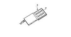
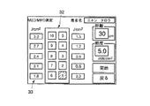
また、装置本体2は、照射エネルギー計算部26と、エネルギー比較部27と、開閉制御部と、表示部29とを有する。照射エネルギー計算部26は、紫外線パワー計算部25で計算された紫外線パワーに、タイマ24による照射時間を乗算することにより、照射エネルギーを計算する。エネルギー比較部27は、照射エネルギー計算部26で計算された照射エネルギーを、複数の目標エネルギーに比較し、照射エネルギーが複数の目標エネルギー各々に達するごとに特定の信号を出力する。開閉制御部28は、エネルギー比較部27から信号出力がなされるごとに、患者に装着された図3に示す多孔板3の各窓孔31を順番に閉じるための信号を多孔板3に出力する。多孔板3は典型的には2列×5個で合計10個の窓孔31を備えている。10個の窓孔31に対しては閉じる順番が予め決められている。開閉制御部28から信号を受けるごとに、10個の窓孔31が一つずつ順番に閉じていく。表示部29は、図6に例示するように、多孔板3の窓孔31の配列を模して配列された複数の窓孔マーク32を表示する。各窓孔マーク32に隣接してそれぞれ対応する目標エネルギー値33が表示される。表示部29は、開閉制御部28から信号を受けるごとに、予め決められている閉じる順番に従って複数の窓孔マーク32の表示態様を例えば白黒反転表示に変化させる。
The
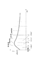
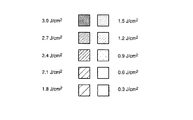
図4には、本実施形態によるMED測定動作の手順を示している。図5に、紫外線パワーの時間変化を示している。MED測定は、図示しないMED測定制御部による制御のもとで各部が動作することにより行われる。まず、メインメニューからMED測定プログラムの起動が指示されると、MED測定プログラムが起動し、図6に例示するようなMED測定用の画面が表示部29に表示される(S11)。この画面には、測定した距離及び測定した照度が、多孔板3の窓孔31の配列を模して配列された10個の窓孔マーク32及びそれぞれの目標エネルギー33とともに表示される。窓孔マーク32内の数字は閉じる順番を表している。目標エネルギー33は、単位(J/cm2)で表示される。目標エネルギー33は、操作者が図示しないマウスやキーボード等の操作部を操作して、数値入力又はプルダウンメニューからの選択等により、それぞれ任意の値に設定される。複数の目標エネルギー33は、初期的には、一定のエネルギー間隔、図6では、0.3(J/cm2)の間隔で設定されるが、一定であることには限定されず、それぞれ任意に設定可能である。説明の便宜上、複数の目標エネルギー33は、0.3(J/cm2)の間隔で設定されるものと仮定する。
FIG. 4 shows the procedure of the MED measurement operation according to the present embodiment. FIG. 5 shows the time change of the ultraviolet power. MED measurement is performed by each part operating under the control of a MED measurement control unit (not shown). First, when an activation of the MED measurement program is instructed from the main menu, the MED measurement program is activated, and a screen for MED measurement illustrated in FIG. 6 is displayed on the display unit 29 (S11). On this screen, the measured distance and the measured illuminance are displayed together with ten
目標エネルギーの設定が完了し、画面内の「開始」ボタンがクリックされたとき、ランプ制御部21から紫外線ランプ11に電力供給が開始され、患者への紫外線照射が開始される(S12)。電力供給に伴ってタイマ24が起動する(S13)。10個の窓孔に対してそれぞれ設定された目標エネルギーのうち、最初の目標エネルギー、つまり最低の目標エネルギーの値がエネルギー比較部27にセットされる。
When the setting of the target energy is completed and the “start” button in the screen is clicked, power supply from the
紫外線測定部22で紫外線光度が測定され(S14)、距離センサ13で紫外線ランプ11から患者までの距離が測定される(S15)。紫外線パワー計算部25により、紫外線測定部22により測定された紫外線の光度と、距離センサ13により測定された紫外線ランプ11から患者までの距離とに基づいて、患者表面での紫外線パワー(照度)が計算される(S16)。計算された紫外線パワー(照度)は照射エネルギー計算部26においてタイマ24の時間に従って時間積分される。それにより照射エネルギーが計算される(S17)。計算された照射エネルギーは、エネルギー比較部27において、1番目の目標エネルギー(0.3J/cm2)と比較される(S18)。照射エネルギーが目標エネルギーに達していないとき、S14に戻り、S14〜S18の処理が、照射エネルギーが1番目の目標エネルギーに達するまで繰り返される。
The ultraviolet light intensity is measured by the ultraviolet light measuring unit 22 (S14), and the distance from the
照射エネルギーが1番目の目標エネルギーに達したとき、エネルギー比較部27は特定の信号を発生する。それにより開閉制御部28の制御により第1の窓孔31が閉じ(S19)、また図6に示すように第1の窓孔31に対応するマーク32が白黒反転される(S20)。全ての窓孔31が閉じていなければ(S21)、2番目の目標エネルギーがエネルギー比較部27にセットされる(S22)。そして、同様に、S14〜S18の処理が、照射エネルギーが2番目の目標エネルギーに達するまで繰り返される。
When the irradiation energy reaches the first target energy, the
照射エネルギーが2番目の目標エネルギー(0.6J/cm2)に達したとき、エネルギー比較部27は特定の信号を発生する。それにより開閉制御部28の制御により第2の窓孔31が閉じ(S19)、また第2の窓孔31に対応するマーク32が白黒反転される(S20)。
When the irradiation energy reaches the second target energy (0.6 J / cm 2 ), the
このような動作が繰り返されることで、複数の窓孔31がそれぞれ設定された目標エネルギーに照射エネルギーが達するごとに順番に閉じられていく。図6の例では、目標エネルギーの間隔を0.3J/cm2に設定しているので、照射エネルギーが0.3J/cm2上昇するごとに窓孔31が一つずつ閉じていく。全ての窓孔31が閉じた時点で(S21)、紫外線照射の停止(S23)とともに当該MED測定動作が終了する。 By repeating such an operation, the plurality of window holes 31 are sequentially closed each time the irradiation energy reaches the set target energy. In the example of FIG. 6, since setting the interval of the target energy 0.3 J / cm 2, window holes 31 is gradually closed one by one every time the irradiation energy 0.3 J / cm 2 increases. When all the window holes 31 are closed (S21), the MED measurement operation is completed together with the stop of ultraviolet irradiation (S23).
操作者は、図7に示す照射エネルギーが相違する10個の紅斑の中から特定の紅斑を選択し、その紅斑に対応する照射エネルギーを1MEDとして、数値入力または複数の窓孔マーク32のいずれかをクリック選択することにより装置に入力する。 The operator selects a specific erythema from 10 erythema having different irradiation energies shown in FIG. 7, and sets the irradiation energy corresponding to the erythema as 1 MED, either numerical input or a plurality of window hole marks 32. Click to select and input to the device.
以上のように本実施形態によると、従来のように窓孔ごとに照射時間を変えながら患者に紫外線を照射してMEDを測定するのではなく、窓孔ごとに照射エネルギーを変えながら患者に紫外線を照射してMEDを測定するので、図7に示すように、紅斑と照射エネルギーとの対応関係が直感的に理解され得る。従来では紅斑と照射時間との対応関係が直感的に理解されるが、紅斑と照射エネルギーとの対応関係を得るためには紫外線エネルギーの乗算が必要とされるため直感的に理解されない。実際に、1MEDを装置に入力するためには、従来では、10個の紅斑の中から特定の紅斑を選択し、その紅斑に対応する照射時間をランプ固有の紫外線パワーに乗算する事が必要とされた。しかし、本実施形態では、10個の紅斑の中から特定の紅斑を選択し、その紅斑に対応する照射エネルギーそれ自体が既に1MEDを表している。従って1MEDに対応する照射エネルギーを直接的に把握することができる。 As described above, according to the present embodiment, instead of measuring the MED by irradiating the patient with ultraviolet rays while changing the irradiation time for each window hole as in the prior art, the patient is irradiated with ultraviolet rays while changing the irradiation energy for each window hole. As shown in FIG. 7, the correspondence between erythema and irradiation energy can be intuitively understood. Conventionally, the correspondence between erythema and irradiation time is intuitively understood, but in order to obtain the correspondence between erythema and irradiation energy, it is not intuitively understood because multiplication of ultraviolet energy is required. Actually, in order to input 1 MED to the apparatus, conventionally, it is necessary to select a specific erythema from 10 erythema and multiply the irradiation time corresponding to the erythema by the ultraviolet power specific to the lamp. It was done. However, in this embodiment, a specific erythema is selected from 10 erythema, and the irradiation energy itself corresponding to the erythema already represents 1 MED. Therefore, it is possible to directly grasp the irradiation energy corresponding to 1 MED.
また、従来では事前計測又は装置固有の一定値としての紫外線パワーに単純に照射時間を乗算することで照射エネルギーを求めていた。しかし、図5に示すように、紫外線ランプ11は、典型的には光度は点灯直後に急峻に上昇し、その後、緩やかに固有値に接近する特性を有している。従って照射エネルギーの測定精度は低い。それに対して本実施形態では、随時測定した紫外線パワーを時間積分することで照射エネルギーを求めるので、より正確な照射エネルギーを求めることができる。
Conventionally, the irradiation energy is obtained by simply multiplying the irradiation time by the ultraviolet power as a fixed value specific to the prior measurement or the apparatus. However, as shown in FIG. 5, the
なお、本発明は上記実施形態そのままに限定されるものではなく、実施段階ではその要旨を逸脱しない範囲で構成要素を変形して具体化できる。また、上記実施形態に開示されている複数の構成要素の適宜な組み合わせにより、種々の発明を形成できる。例えば、実施形態に示される全構成要素から幾つかの構成要素を削除してもよい。さらに、異なる実施形態にわたる構成要素を適宜組み合わせてもよい。 Note that the present invention is not limited to the above-described embodiment as it is, and can be embodied by modifying the constituent elements without departing from the scope of the invention in the implementation stage. In addition, various inventions can be formed by appropriately combining a plurality of components disclosed in the embodiment. For example, some components may be deleted from all the components shown in the embodiment. Furthermore, constituent elements over different embodiments may be appropriately combined.
1…ランプハウス、2…計算機ユニット、3…多孔板、4…寝台、5…被検体、11…紫外線ランプ、12…紫外線センサ、13…距離センサ、21…ランプ制御部、22…紫外線測定部、23…距離測定部、24…タイマ、25…紫外線パワー計算部、26…照射エネルギー計算部、27…エネルギー比較部、28…開閉制御部、29…表示部。
DESCRIPTION OF
Claims (7)
前記紫外線のパワーを繰り返し測定する紫外線パワー測定手段と、
前記測定される紫外線のパワーと照射時間とに基づいて照射エネルギーを繰り返し計算する手段と、
前記計算される照射エネルギーが複数の目標エネルギー各々に達するごとに特定の信号を出力する手段とを具備することを特徴とする紫外線治療器。 An ultraviolet lamp that generates ultraviolet rays on the subject;
UV power measuring means for repeatedly measuring the power of the UV light;
Means for repeatedly calculating the irradiation energy based on the measured ultraviolet power and irradiation time;
And a means for outputting a specific signal each time the calculated irradiation energy reaches each of a plurality of target energies.
Priority Applications (1)
| Application Number | Priority Date | Filing Date | Title |
|---|---|---|---|
| JP2004120477A JP2005296504A (en) | 2004-04-15 | 2004-04-15 | UV therapy device |
Applications Claiming Priority (1)
| Application Number | Priority Date | Filing Date | Title |
|---|---|---|---|
| JP2004120477A JP2005296504A (en) | 2004-04-15 | 2004-04-15 | UV therapy device |
Related Child Applications (1)
| Application Number | Title | Priority Date | Filing Date |
|---|---|---|---|
| JP2009235133A Division JP4898885B2 (en) | 2009-10-09 | 2009-10-09 | UV therapy device |
Publications (1)
| Publication Number | Publication Date |
|---|---|
| JP2005296504A true JP2005296504A (en) | 2005-10-27 |
Family
ID=35328752
Family Applications (1)
| Application Number | Title | Priority Date | Filing Date |
|---|---|---|---|
| JP2004120477A Pending JP2005296504A (en) | 2004-04-15 | 2004-04-15 | UV therapy device |
Country Status (1)
| Country | Link |
|---|---|
| JP (1) | JP2005296504A (en) |
Cited By (2)
| Publication number | Priority date | Publication date | Assignee | Title |
|---|---|---|---|---|
| CN108295379A (en) * | 2017-01-12 | 2018-07-20 | 财团法人工业技术研究院 | Light source module, phototherapy device and using method thereof |
| JP2023500421A (en) * | 2019-10-30 | 2023-01-06 | フィールドポイント (キプロス) リミテッド | Therapeutic irradiation equipment |
-
2004
- 2004-04-15 JP JP2004120477A patent/JP2005296504A/en active Pending
Cited By (3)
| Publication number | Priority date | Publication date | Assignee | Title |
|---|---|---|---|---|
| CN108295379A (en) * | 2017-01-12 | 2018-07-20 | 财团法人工业技术研究院 | Light source module, phototherapy device and using method thereof |
| JP2023500421A (en) * | 2019-10-30 | 2023-01-06 | フィールドポイント (キプロス) リミテッド | Therapeutic irradiation equipment |
| US12290698B2 (en) | 2019-10-30 | 2025-05-06 | Fieldpoint (Cyprus) Limited | Therapeutic irradiation device |
Similar Documents
| Publication | Publication Date | Title |
|---|---|---|
| US8353846B2 (en) | Method and apparatus for tinnitus evaluation | |
| Madison et al. | Effects of practice on variability in an isochronous serial interval production task: asymptotical levels of tapping variability after training are similar to those of musicians | |
| US20080276192A1 (en) | Method and apparatus for controlling an electromagnetic energy output system | |
| KR102236565B1 (en) | Digital piano with ultraviolet sterilization function | |
| RU2611748C2 (en) | Mobile x-ray unit | |
| AU2003230522A1 (en) | Method for performing in vivo dosimetry | |
| JP7041245B6 (en) | Phototherapy system and method | |
| JP2018532524A (en) | Device for performing light therapy | |
| JP4378957B2 (en) | Physiological state induction device | |
| WO2016045517A1 (en) | Respiratory guiding device and method in respiratory gating ion beam irradiation | |
| US10456189B2 (en) | RF generator for an electrosurgical instrument | |
| US10146393B2 (en) | Method and apparatus pertaining to radiation treatment plan optimization states | |
| ATE406861T1 (en) | MULTIFUNCTIONAL KORYO THERAPY DEVICE | |
| JP4898885B2 (en) | UV therapy device | |
| JP2005177158A (en) | Sleep support device and program | |
| US20070093733A1 (en) | Method and apparatus for treatment of predominant-tone tinnitus | |
| JP2005296504A (en) | UV therapy device | |
| KR101340359B1 (en) | Laser device that can change the diameter of the pulsed laser beam for tactile control and method using the same | |
| CN203689072U (en) | Circuit of stress-releasing sleep-facilitating device | |
| US20080049946A1 (en) | Self-paced in-situ audiometry | |
| KR20230156011A (en) | Massage apparatus for providing microcurrent stimulation massage and operation thereof | |
| JP7575637B1 (en) | Phototherapy Device | |
| KR20050120105A (en) | Apparatus and method for aroma therapy based on user's health state | |
| GB2458165A (en) | Handheld electric treatment apparatus additionally providing audio playback for entertainment of a young patient | |
| JP2008292439A (en) | Wake-up device |
Legal Events
| Date | Code | Title | Description |
|---|---|---|---|
| A621 | Written request for application examination |
Free format text: JAPANESE INTERMEDIATE CODE: A621 Effective date: 20070404 |
|
| A977 | Report on retrieval |
Free format text: JAPANESE INTERMEDIATE CODE: A971007 Effective date: 20081113 |
|
| A131 | Notification of reasons for refusal |
Free format text: JAPANESE INTERMEDIATE CODE: A131 Effective date: 20081118 |
|
| A521 | Written amendment |
Free format text: JAPANESE INTERMEDIATE CODE: A523 Effective date: 20090107 |
|
| A02 | Decision of refusal |
Free format text: JAPANESE INTERMEDIATE CODE: A02 Effective date: 20090714 |
|
| A521 | Written amendment |
Free format text: JAPANESE INTERMEDIATE CODE: A523 Effective date: 20091009 |
|
| A521 | Written amendment |
Free format text: JAPANESE INTERMEDIATE CODE: A821 Effective date: 20091125 |