JP2005296430A - Ultrasonic surgical system - Google Patents
Ultrasonic surgical system Download PDFInfo
- Publication number
- JP2005296430A JP2005296430A JP2004118771A JP2004118771A JP2005296430A JP 2005296430 A JP2005296430 A JP 2005296430A JP 2004118771 A JP2004118771 A JP 2004118771A JP 2004118771 A JP2004118771 A JP 2004118771A JP 2005296430 A JP2005296430 A JP 2005296430A
- Authority
- JP
- Japan
- Prior art keywords
- ultrasonic
- surgical instrument
- resistance value
- ultrasonic transducer
- switch
- Prior art date
- Legal status (The legal status is an assumption and is not a legal conclusion. Google has not performed a legal analysis and makes no representation as to the accuracy of the status listed.)
- Granted
Links
- 238000001514 detection method Methods 0.000 claims abstract description 29
- 238000001356 surgical procedure Methods 0.000 claims abstract description 22
- 238000012790 confirmation Methods 0.000 claims abstract description 7
- 238000009413 insulation Methods 0.000 abstract description 32
- 238000002955 isolation Methods 0.000 description 5
- 239000007788 liquid Substances 0.000 description 5
- 238000004140 cleaning Methods 0.000 description 4
- 238000000034 method Methods 0.000 description 3
- 238000010586 diagram Methods 0.000 description 2
- 239000002184 metal Substances 0.000 description 2
- 230000001954 sterilising effect Effects 0.000 description 2
- 238000004659 sterilization and disinfection Methods 0.000 description 2
- 239000000645 desinfectant Substances 0.000 description 1
- 230000002708 enhancing effect Effects 0.000 description 1
- 238000007689 inspection Methods 0.000 description 1
- 238000010030 laminating Methods 0.000 description 1
- 238000012544 monitoring process Methods 0.000 description 1
- 230000000737 periodic effect Effects 0.000 description 1
- XLYOFNOQVPJJNP-UHFFFAOYSA-N water Substances O XLYOFNOQVPJJNP-UHFFFAOYSA-N 0.000 description 1
Images
Landscapes
- Surgical Instruments (AREA)
Abstract
Description
本発明は超音波手術器に関し、特に超音波振動子の適正動作を確保するための技術に関する。 The present invention relates to an ultrasonic surgical instrument, and more particularly to a technique for ensuring proper operation of an ultrasonic transducer.
超音波手術器は、ホーンなどの手術具、その手術具に超音波振動を伝達する超音波振動子、その超音波振動子へ駆動信号を供給する駆動回路、などを有する。超音波振動する手術具が生体組織へ当てられると、その組織が破砕等され、これによって超音波手術が行われる。超音波振動子としては、ランジュバン型超音波振動子(代表的にはボルト締め型超音波振動子)が周知である。かかる超音波振動子は、複数の圧電板、それらの間及び両側に設けられた電極板、複数の圧電板及び複数の電極板からなる積層体を貫通してそれらを締結するボルト部材、などを有する。複数の電極板に対しては、互い違いに正極と負極とが設定され、同極同士が電気的に接続される。つまり、超音波振動子には正極端子及び負極端子が設けられ、それらの端子間に高電圧の駆動信号が印加される。 The ultrasonic surgical instrument includes a surgical instrument such as a horn, an ultrasonic vibrator that transmits ultrasonic vibration to the surgical tool, a drive circuit that supplies a drive signal to the ultrasonic vibrator, and the like. When a surgical tool that vibrates ultrasonically is applied to a living tissue, the tissue is crushed and ultrasonic surgery is performed. As an ultrasonic transducer, a Langevin type ultrasonic transducer (typically a bolted ultrasonic transducer) is well known. Such an ultrasonic vibrator includes a plurality of piezoelectric plates, electrode plates provided between and on both sides thereof, a bolt member that penetrates a laminated body including a plurality of piezoelectric plates and a plurality of electrode plates, and fastens them. Have. For a plurality of electrode plates, a positive electrode and a negative electrode are alternately set, and the same electrode is electrically connected. That is, the ultrasonic vibrator is provided with a positive terminal and a negative terminal, and a high-voltage drive signal is applied between these terminals.
下記特許文献1には、超音波手術具が正常な使用状態か否かを判断するために駆動信号の周波数を変化させ、その時の共振状態を検出することが記載されている。しかし、駆動信号を供給してみないと、つまり超音波振動子を実際に振動させてみないと、状態判定を行えないという問題がある。
ところで、超音波手術器に内蔵される超音波振動子において、そこに含まれる圧電体の抵抗値は本来およそ無限大くらい非常に大きいものである。しかし、超音波手術器の消毒処理や滅菌処理などに起因して超音波手術器の内部に水や消毒液などの液体が入り込み、それによって超音波振動子の各電極間における絶縁性が低下する可能性を否定できない。従来装置において、仮に絶縁性が低下して駆動信号の供給状態に変化(電流値、電圧値、アドミッタンス値などの変化)が生じた場合には安全回路が動作して超音波手術器の動作が停止することになるが、より一層安全性を高めることが求められる。特に駆動信号の供給前に超音波振動子の絶縁性を確認しておくのが望ましい。 By the way, in the ultrasonic vibrator built in the ultrasonic surgical instrument, the resistance value of the piezoelectric body included therein is inherently very large, approximately infinite. However, liquids such as water and disinfectant liquid enter the ultrasonic surgical instrument due to the sterilization and sterilization processes of the ultrasonic surgical instrument, thereby reducing the insulation between the electrodes of the ultrasonic transducer. The possibility cannot be denied. In the conventional apparatus, if the insulation is lowered and the supply state of the drive signal changes (changes in current value, voltage value, admittance value, etc.), the safety circuit operates and the ultrasonic surgical instrument operates. Although it will stop, it is required to further improve safety. In particular, it is desirable to confirm the insulation of the ultrasonic transducer before supplying the drive signal.
本発明の目的は、超音波手術器における安全性をより高められるようにすることにある。 An object of the present invention is to further improve safety in an ultrasonic surgical instrument.
本発明の他の目的は、超音波振動子の絶縁性の程度に応じて安全性を確保するための適切な制御を行えるようにすることにある。 Another object of the present invention is to enable appropriate control for ensuring safety according to the degree of insulation of an ultrasonic transducer.
本発明は、手術具に対して超音波振動を伝達する超音波振動子と、超音波手術に際して、前記超音波振動子に対して駆動信号を供給する駆動回路と、超音波手術に先立って、前記超音波振動子における端子間の抵抗値を検出する検出部と、前記抵抗値に基づいて、当該超音波手術器の動作安全性を高める制御を実行する制御部と、を含むことを特徴とする。 The present invention, prior to ultrasonic surgery, an ultrasonic transducer that transmits ultrasonic vibration to a surgical instrument, a drive circuit that supplies a drive signal to the ultrasonic transducer during ultrasonic surgery, A detection unit that detects a resistance value between terminals in the ultrasonic transducer, and a control unit that executes control for improving the operational safety of the ultrasonic surgical device based on the resistance value. To do.
上記構成によれば、駆動信号を超音波振動子へ供給する前に、検出部によって超音波振動子における端子間の抵抗値が実際に検出され、その抵抗値に基づいて安全性の観点から制御が実行される。 According to the above configuration, the resistance value between the terminals of the ultrasonic transducer is actually detected by the detection unit before the drive signal is supplied to the ultrasonic transducer, and control is performed from the viewpoint of safety based on the resistance value. Is executed.
端子間の抵抗値は、一定電圧を印加した場合における電圧、あるいは、他の情報として検出することができる。望ましくは、抵抗値の大きさが1又は複数の基準値と比較され、これによって絶縁性の程度が判断される。絶縁性が大きく低下している場合、ユーザーに対してその旨を報知し且つ超音波手術器の動作を禁止するようにするのが望ましい。絶縁性が低下しているが使用可能な場合においては、ユーザーにその旨を報知し、その上でユーザーの確認入力を待って超音波手術器の動作を許容するのが望ましい。もちろん、安全性を確保するための制御内容としては、上記の報知や動作禁止以外にも、超音波手術器の出力パワーの制限、動作時間の制限、その他の制限をあげることができる。 The resistance value between the terminals can be detected as a voltage when a constant voltage is applied or as other information. Preferably, the magnitude of the resistance value is compared with one or more reference values, thereby determining the degree of insulation. If the insulation is greatly deteriorated, it is desirable to notify the user and prohibit the operation of the ultrasonic surgical instrument. In the case where the insulation is deteriorated but can be used, it is desirable to notify the user of the fact and wait for the user's confirmation input before allowing the operation of the ultrasonic surgical instrument. Of course, the control content for ensuring safety can include the output power limit, the operation time limit, and other restrictions of the ultrasonic surgical instrument in addition to the above notification and operation prohibition.
望ましくは、前記制御部は、前記抵抗値が通常範囲にある場合には当該超音波手術器を通常動作させ、前記抵抗値が前記通常範囲よりも低い動作禁止範囲にある場合には第1アラームを出力し且つ前記超音波振動子への前記駆動信号の供給を禁止する。この構成によれば、絶縁性が大きく低下している旨がユーザー側へ伝達されるのでユーザーにハンドピース交換等の必要性を認識させることができ、また強制的に使用禁止状態となるので安全である。 Preferably, the control unit causes the ultrasonic surgical device to normally operate when the resistance value is in a normal range, and a first alarm when the resistance value is in an operation prohibition range lower than the normal range. And the supply of the drive signal to the ultrasonic transducer is prohibited. According to this configuration, since the fact that the insulation performance has greatly deteriorated is transmitted to the user side, the user can be made aware of the necessity of handpiece replacement and the use is forcibly prohibited. It is.
望ましくは、前記制御部は、更に、前記抵抗値が前記通常範囲と前記動作禁止範囲の間に設定された動作選択範囲にある場合には第2アラームを出力し、その後のユーザーの確認入力があった場合に前記超音波振動子への前記駆動信号の供給を許容する。この構成によれば、絶縁性がやや低下しているような場合(使用可能であるが絶縁性が通常よりも低い場合)において、その事態がユーザーに報知されるので、現状のハンドピースのそのままの使用、ハンドピース交換、ハンドピースの使用断念などを諸状況(生体側の状態、手術の内容や時間など)に応じてユーザー側で判断できる。そのまま現状のハンドピースを使用する場合でもユーザーの確認入力を待ってからその使用がはじめて許容されるので、安全性を高められる。 Preferably, the control unit further outputs a second alarm when the resistance value is in an operation selection range set between the normal range and the operation prohibition range, and the user's confirmation input thereafter. If there is, supply of the drive signal to the ultrasonic transducer is allowed. According to this configuration, in a case where the insulation is slightly deteriorated (when it is usable but the insulation is lower than usual), the situation is notified to the user. Use, handpiece replacement, and abandonment of handpiece use can be determined by the user according to various situations (biological condition, operation content, time, etc.). Even when the current handpiece is used as it is, its use is allowed for the first time after waiting for the user's confirmation input, so the safety can be improved.
望ましくは、前記超音波振動子と前記駆動回路との間に設けられたオンオフ動作する第1のスイッチ回路と、前記超音波振動子と前記検出部との間に設けられたオンオフ動作する第2のスイッチと、を含み、前記制御部は、前記超音波手術に先立って前記抵抗値を検出する場合に前記第1のスイッチをオフ状態にし且つ前記第2のスイッチをオン状態にし、前記超音波手術に際しては前記第1のスイッチをオン状態にし且つ前記第2のスイッチをオフ状態にする。 Preferably, a first switch circuit provided between the ultrasonic transducer and the drive circuit and performing an on / off operation, and a second switch circuit provided between the ultrasonic transducer and the detection unit. The control unit turns off the first switch and turns on the second switch when the resistance value is detected prior to the ultrasonic surgery, and turns on the ultrasonic switch. During the operation, the first switch is turned on and the second switch is turned off.
上記構成によれば、第1のスイッチ回路によって超音波振動子と駆動回路との電気的な接続の有無を切り換えることができ、第2のスイッチ回路によって超音波振動子と検出部との電気的な接続の有無を切り換えることができる。よって、抵抗値の検出時においては、超音波振動子から駆動回路を電気的に切り離して正確な検出を行うことができ、超音波手術時においては検出部を超音波振動子から電気的に切り離して生体安全性を高められる。 According to the above configuration, the first switch circuit can switch the presence / absence of electrical connection between the ultrasonic transducer and the drive circuit, and the second switch circuit can electrically switch between the ultrasonic transducer and the detection unit. The presence or absence of a simple connection can be switched. Therefore, when detecting the resistance value, the drive circuit can be electrically separated from the ultrasonic transducer for accurate detection, and during ultrasonic surgery, the detection unit can be electrically separated from the ultrasonic transducer. To improve biosafety.
望ましくは、前記検出部は、前記超音波振動子の端子間に直流電圧を印加するための直流電源と、前記直流電圧が印加された状態において、前記超音波振動子における端子間の抵抗値を電圧として検出する電圧検出回路と、を含む。 Preferably, the detection unit is configured to determine a resistance value between the terminals of the ultrasonic transducer in a state where the DC voltage is applied and a DC power source for applying a DC voltage between the terminals of the ultrasonic transducer. And a voltage detection circuit that detects the voltage.
望ましくは、当該超音波手術器は、手術器本体と、前記超音波振動子を内蔵し前記手術器本体に接続されるハンドピースと、で構成され、前記手術器本体に対して前記ハンドピースが接続された時に、前記端子間の抵抗値が検出される。 Preferably, the ultrasonic surgical instrument includes a surgical instrument main body and a handpiece that includes the ultrasonic transducer and is connected to the surgical instrument main body, and the handpiece is connected to the surgical instrument main body. When connected, the resistance value between the terminals is detected.
以上説明したように、本発明によれば、超音波手術の前に端子間の抵抗値が実際に測定されるので、超音波手術器における安全性をより高められる。本発明によれば、超音波振動子の絶縁性の程度に応じて安全性を確保するための適切な制御を行える。 As described above, according to the present invention, since the resistance value between the terminals is actually measured before the ultrasonic operation, the safety in the ultrasonic surgical instrument can be further improved. According to the present invention, appropriate control for ensuring safety can be performed according to the degree of insulation of the ultrasonic transducer.
以下、本発明の好適な実施形態を図面に基づいて説明する。 DESCRIPTION OF EXEMPLARY EMBODIMENTS Hereinafter, preferred embodiments of the invention will be described with reference to the drawings.
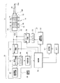
図1には、本発明に係る超音波手術器の好適な実施形態が示されており、図1はその全体構成を示すブロック図である。この超音波手術器は、生体組織に対して超音波振動を伝達し、これによって組織の破砕などの処置を行うものである。生体に対して外科的な手術を行う器具であるため、超音波手術器に関しては高い安全性が要請される。 FIG. 1 shows a preferred embodiment of an ultrasonic surgical instrument according to the present invention, and FIG. 1 is a block diagram showing the overall configuration thereof. This ultrasonic surgical device transmits ultrasonic vibrations to a living tissue, thereby performing a treatment such as tissue crushing. Since this is an instrument for performing a surgical operation on a living body, high safety is required for an ultrasonic surgical instrument.
超音波手術器は、本体10とハンドピース12とで構成される。ハンドピース12は本体10に対して図示されていないケーブルを介して着脱自在に接続される。ハンドピース12は、医者などの使用者によって把持される。ハンドピース12は、図示されるように超音波振動子14を有している。超音波振動子14はこの例ではいわゆるボルト締め型超音波振動子である。すなわち、超音波振動子14は、積層された複数の圧電板16と、それらの圧電板の間及び両端に設けられた複数の電極板18とを有し、それらを積層して構成される積層体がその前後に設けられた一対の金属ブロック19A,19Bによって挟まれた構造を有している。一対の金属ブロック19A,19Bは図示されていないボルトによって互いに締結されている。この構成自体は公知である。超音波振動子14にて生じた超音波振動は手術具としてのホーン17に伝達され、その先端部17Aによって超音波手術が実行される。
The ultrasonic surgical instrument includes a
より具体的に説明すると、ハンドピースの軸方向に複数の電極板18が並んでおり、それらの電極板は互い違いに配置された複数のプラス電極板及び複数のマイナス電極板で構成される。複数のプラス電極板はプラス端子(プラス側ライン)に接続されており、それが符号20によって表されている。複数のマイナス電極板はマイナス端子(マイナス側ライン)に接続されており、それが符号22によって表されている。このような結線関係により、端子間に駆動信号を供給すると、それぞれの圧電板において超音波振動が同相で生じ、超音波振動子全体として大きな振幅が得られる。ちなみに、ハンドピース12には、洗浄液を手術部位へ注ぎ込む機構、手術部位から洗浄液等を吸引する機構なども備わっているが、それらの構成については図1においては図示省略されている。また、ハンドピース12には各種スイッチが備わっているが、それらについても図示省略されている。
More specifically, a plurality of
本体10について説明する。本体10は超音波駆動回路30を有している。この超音波駆動回路30は、所定の周波数を持った駆動信号を生成する。その駆動信号はトランス32によって昇圧されて第1スイッチ回路34を介して超音波振動子14へ供給される。トランス32は、一次側電圧を所定倍率をもって昇圧して二次側電圧とする回路である。ここで超音波振動子14に供給される駆動信号の電圧は例えば300Vである。ちなみにその駆動信号の周波数や周期パターンなどについては手術モード等により適宜変更することができる。
The
第1スイッチ回路34は、超音波手術の実行時においてのみオン動作するものである。すなわち、ハンドピース12に設けられた図示されていない手術実行スイッチが操作されると、制御部38によってそれが検知され、制御部38から超音波駆動回路30に対して信号出力命令が出され、同時に、第1スイッチ回路34に対してオン動作信号が出力される。
The
本実施形態に係る超音波手術器には絶縁性検出部36が設けられている。絶縁性検出部36は、超音波手術に先立って超音波振動子14における両端子間の絶縁抵抗値を検出するものである。すなわち超音波振動子14の絶縁性の程度(良否)を測定する回路である。
The ultrasonic surgical instrument according to the present embodiment is provided with an insulating
直流電圧発生回路40は、一定の直流(DC)電圧を生成する。その直流電圧は抵抗ブリッジ回路42及び第2スイッチ回路44を介して超音波振動子14の一対の端子20,22に印加される。
The direct current
第2スイッチ回路44は、抵抗値の検出時のみオン動作するスイッチ回路である。抵抗ブリッジ回路42は、超音波振動子14の抵抗値を電圧として検出するための公知のホイートストンブリッジ回路として構成されている。抵抗ブリッジ回路42における特定抵抗の両端電圧は差動動作するアイソレーションアンプ46によって一定の比率で電圧変換され、アイソレーションアンプ46から出力される検出信号の電圧が判定回路48に入力される。判定回路48は両端子間の抵抗値に相当する電圧値を複数のしきい値と比較し、これによって超音波振動子14の絶縁性の程度を判定する。その判定結果は制御部38へ出力される。
The
制御部38は、図1に示される各構成の動作制御を行っており、特に絶縁性検出部36から出力される判定信号に基づいて当該超音波手術器の動作にあたってその安全性を高めるための制御を実行している。絶縁性の程度がある一定値以上であれば(抵抗値が後述の通常範囲にあれば)通常の超音波手術動作が許容され、絶縁性の程度がそれよりも下回った場合(抵抗値が後述の選択動作範囲又は動作禁止範囲に入った場合)にはその低下度合いに応じて適切な安全制御を実行する。例えば、超音波手術自体の禁止あるいはユーザーへの警告などの制御が実行される。制御部38には表示器51及びスピーカ53が接続されている。それらの表示器51及びスピーカ53を利用してユーザーに対してアラームが報知される。
The
後に説明するように、制御部38は、本体10に対してハンドピース12を接続した時点あるいは装置の電源の立ち上げ時において、つまり超音波手術を行う以前の振動子検査が必要なタイミングで、絶縁性検出部36を動作させ、その場合に第2スイッチ回路44をオン動作させる。そのような抵抗値の検出が完了した時点で、第2スイッチ回路44はオフ状態となる。つまり、第1スイッチ回路34は超音波手術の実行時のみオン動作し、第2スイッチ回路44は抵抗値の検出時のみオン動作する。それらの両スイッチ回路が同時にオン動作することは制御部38によって禁止されている。
As will be described later, the
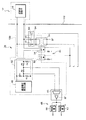
次に、図2を用いて図1に示した絶縁性検出部36の具体的な構成例について説明する。上述したように、直流電圧発生回路40と超音波振動子14との間には抵抗ブリッジ回路42及び第2スイッチ回路44が設けられている。抵抗ブリッジ回路42は図示されるように抵抗R1〜R5の5つの抵抗によって構成される。ここで抵抗R5の両端電圧がアイソレーションアンプ46によって検出されている。アイソレーションアンプ46から出力される検出信号は判定回路48に入力されている。
Next, a specific configuration example of the
判定回路48は、図2に示す例において並列配置された2つの判定器60,62に入力されている。判定器60は検出信号の電圧(抵抗値Rに相当)と第1基準電圧(基準抵抗値αに相当)とを比較し、検出信号の電圧が第1基準電圧よりも高い場合に、Hi信号を出力し、それ以外の場合にLo信号を出力する。一方、判定器62においては、検出信号の電圧と第2基準電圧(基準抵抗値βに相当)とが比較され、判定器62は、検出信号の電圧が第2基準電圧よりも高い場合にHi信号を出力し、それ以外の場合にLo信号を出力する。ここで、α>βの関係があり、すなわち判定回路48は、検出される抵抗値が3つの区分(範囲)のいずれに属するかを判定している。この例では、正常範囲、やや劣化したとみなせる範囲(選択動作範囲)、かなり劣化したと認められる範囲(動作禁止範囲)の3つの範囲がある。後に説明するように、抵抗値が正常範囲内にある場合には通常の超音波手術動作がそのまま許容され、抵抗値が選択動作範囲内にある場合にはユーザーにその事実を報知した上でユーザーの確認入力をまって超音波手術を許容している。この場合においては必要に応じて安全性の観点からパワーなどの上限値が引き下げられる。抵抗値が動作禁止範囲にある場合には超音波手術の実行が禁止される。ここで第1基準電圧(つまりα)及び第2基準電圧(つまりβ)の値はあらかじめ固定的に設定しておくこともできるし、諸状況に応じて適切な値を可変設定することもできる。いずれにしても、超音波振動子14における抵抗値を実際に測定して、それによって超音波振動子14についての状態を確認した上で超音波手術を遂行させることが可能となる。
The
第2スイッチ回路44は、図示されるように、プラスライン及びマイナスラインにそれぞれ設けられた2つのフォトカプラ56,58によって構成されている。フォトカプラ56,58は図1に示した制御部からの信号に応じてオン又はオフ動作する。
As shown in the figure, the
また、トランス32と超音波振動子14との間には第1スイッチ回路34が設けられている。この第1スイッチ回路34はプラスライン及びマイナスラインのそれぞれに設けられた2つのスイッチ50,52によって構成される。そして、図1に示した制御部からオン動作信号が与えられると、リレー54が動作し、これによって各スイッチ50,52がオン動作する。
A
ちなみに、符号102は本体における筐体を表している。また符号100は絶縁されたユニット部分を表している。すなわち、ハンドピース12及び絶縁性検出部36を含めてそれ以外から直流的に浮いた状態が形成されており、ハンドピースに対して何らかの事情によって高電圧が印加してしまうことを未然に防止できる。
Incidentally, the code |
ちなみに、抵抗ブリッジ回路42は、超音波振動子14における端子間の抵抗値の大きさに反比例した電圧信号を出力する。上記の直流電圧は例えば200Vであり、また絶縁性検出部36において検出できる抵抗値の範囲は例えば0MΩ〜5000MΩである。その範囲に対応してアイソレーションアンプ46からは例えば0〜5Vのアナログ電圧信号としての検出信号が出力される。また、上記の第1基準電圧は例えば抵抗値1000MΩに相当する値であり、上記の第2基準電圧は例えば抵抗値10MΩに相当する値である。もちろんそれらの数値は一例である。抵抗ブリッジ回路42は上記の広範な抵抗値モニタリングに適しているものである。
Incidentally, the
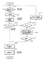
次に、図3を用いて、図1に示した超音波手術器の動作を説明する。初期状態においては、第1スイッチ回路34(以下、SW1)はオフ状態にあり、第2スイッチ回路44(以下、SW2)もオフ状態にある。 Next, the operation of the ultrasonic surgical instrument shown in FIG. 1 will be described with reference to FIG. In the initial state, the first switch circuit 34 (hereinafter referred to as SW1) is in an off state, and the second switch circuit 44 (hereinafter referred to as SW2) is also in an off state.
S101において、本体に対してハンドピースが接続されたと判断されると、あるいは、ハンドピースが本体に接続された状態において電源が投入されると、必要に応じて、S102において電気的な回路の安定化のために一定時間経過まで待機状態とされ、その後、S103において絶縁性検出部36によって超音波振動子における両端子間の抵抗値Rが検出される。この検出にあたっては、SW2のみがオン動作する。そして検出後にSW2はオフ動作する。
If it is determined in S101 that the handpiece is connected to the main body, or if the power is turned on while the handpiece is connected to the main body, the electrical circuit is stabilized in S102 as necessary. In order to make it into a standby state, a standby state is maintained until a predetermined time elapses. Thereafter, in S103, the
S104では、抵抗値Rが第1基準値αよりも大きいか否かが判断され、その条件が満たされた場合にはS105が実行される。その一方において、S104の条件が満たされない場合には、更にS107において抵抗値Rが第2基準値βよりも大きいか否かが判断される。その条件が満たされればS108が実行され、満たされなければS110が実行される。すなわち、S104及びS107において、抵抗値Rが、通常範囲(R>α)、動作選択範囲(α>R>β)、動作禁止範囲(β>R)のいずれに属するのかが判断される。但し、通常範囲と動作禁止範囲の2つの範囲を設けてもよく、また4つ以上の範囲を設けてもよい。 In S104, it is determined whether or not the resistance value R is larger than the first reference value α. If the condition is satisfied, S105 is executed. On the other hand, if the condition of S104 is not satisfied, it is further determined in S107 whether or not the resistance value R is greater than the second reference value β. If the condition is satisfied, S108 is executed, and if not satisfied, S110 is executed. That is, in S104 and S107, it is determined whether the resistance value R belongs to the normal range (R> α), the operation selection range (α> R> β), or the operation prohibition range (β> R). However, two ranges of a normal range and an operation prohibition range may be provided, or four or more ranges may be provided.
ここで抵抗値Rが正常範囲内である場合には、S105において超音波手術に先立って、洗浄液の供給及び吸引を行う洗浄システムが作動する。そして、S106においてはハンドピースに設けられた動作スイッチをオンすることにより超音波手術が実行される。この場合においては、SW1がオン動作する。 Here, when the resistance value R is within the normal range, a cleaning system that supplies and sucks the cleaning liquid is operated prior to the ultrasonic operation in S105. In S106, an ultrasonic operation is performed by turning on an operation switch provided on the handpiece. In this case, SW1 is turned on.
一方、抵抗値Rが動作選択範囲に属する場合、S108において表示器51に第2エラーが表示される。すなわち、絶縁性がやや劣化している状態を表すメッセージあるいはそれを表すシンボルなどが表示される。またスピーカ53から第2アラーム音が出力される。第2アラーム音は所定のパターンあるいは音色を持った音である。更に必要であれば、動作条件、例えば出力パワー、についての制限が設定される。
On the other hand, when the resistance value R belongs to the operation selection range, the second error is displayed on the
S109では、上記のような第2エラー表示あるいは第2アラーム音の出力によってその事態を認知したユーザーにより、そのような状態においても超音波手術を実行させるか否かの確認入力が求められる。ここで、そのような入力があればS105以降の工程が実行されるが、そのような入力がなされなければ、あるいは超音波手術を断念する入力がなされればS105以降の工程は実行されない。確認入力はハンドピースに設けられた所定スイッチの操作による。 In S109, the user who has recognized the situation by the second error display or the output of the second alarm sound as described above is required to confirm whether or not to perform the ultrasonic operation even in such a state. Here, if there is such an input, the steps after S105 are executed. However, if such an input is not made, or if an input for giving up the ultrasonic operation is made, the steps after S105 are not executed. The confirmation input is made by operating a predetermined switch provided on the handpiece.
一方、S110においては、絶縁性がかなり低下した状態にあるため、超音波手術の実行が強制的に禁止される。その際には第1エラー表示が出され、また第1アラーム音が出力される。ここで第1エラー表示は当該状態を表すメッセージあるいはシンボルなどを含むものである。第1エラー表示及び第1アラーム音のいずれも、上記の第2エラー表示及び第2アラーム音とは異なる。したがって、ユーザーはS110において上記のような報知を受けた後、ハンドピースを交換するなどの作業をし、ハンドピースが交換された場合にはS102からの各工程が繰り返し実行される。 On the other hand, in S110, since the insulation is in a considerably lowered state, execution of ultrasonic surgery is forcibly prohibited. At that time, a first error display is issued and a first alarm sound is output. Here, the first error display includes a message or a symbol representing the state. Both the first error display and the first alarm sound are different from the second error display and the second alarm sound. Therefore, after receiving the notification as described above in S110, the user performs an operation such as exchanging the handpiece. When the handpiece is exchanged, each process from S102 is repeatedly executed.
以上説明した超音波手術器によれば、超音波手術の実行に先立って超音波振動子についての絶縁性の程度を実際に測定してその絶縁性の程度に応じて超音波手術の安全性を高めるための動作が適用されるので、超音波手術器の動作信頼性を高められると共に、生体安全性を高めることができるという利点がある。 According to the ultrasonic surgical instrument described above, the degree of insulation of the ultrasonic transducer is actually measured prior to the execution of the ultrasonic operation, and the safety of the ultrasonic operation is improved according to the degree of insulation. Since the operation | movement for raising is applied, there exists an advantage that the operation | movement reliability of an ultrasonic surgical instrument can be improved and biological safety can be improved.
10 本体、12 ハンドピース、14 超音波振動子、30 超音波駆動回路、34 第1スイッチ回路、36 絶縁性検出部、38 制御部、42 抵抗ブリッジ回路、44 第2スイッチ回路、48 判定回路。
DESCRIPTION OF
Claims (6)
超音波手術に際して、前記超音波振動子に対して駆動信号を供給する駆動回路と、
超音波手術に先立って、前記超音波振動子における端子間の抵抗値を検出する検出部と、
前記抵抗値に基づいて、当該超音波手術器の動作の安全性を高める制御を実行する制御部と、
を含むことを特徴とする超音波手術器。 An ultrasonic transducer that transmits ultrasonic vibrations to the surgical instrument;
A driving circuit for supplying a driving signal to the ultrasonic transducer during ultrasonic surgery;
Prior to ultrasonic surgery, a detection unit for detecting a resistance value between terminals in the ultrasonic transducer,
Based on the resistance value, a control unit that executes control to increase the safety of the operation of the ultrasonic surgical instrument,
An ultrasonic surgical instrument comprising:
前記制御部は、前記抵抗値が通常範囲にある場合には当該超音波手術器を通常動作させ、前記抵抗値が前記通常範囲よりも低い動作禁止範囲にある場合には第1アラームを出力し且つ前記超音波振動子への前記駆動信号の供給を禁止することを特徴とする超音波手術器。 The ultrasonic surgical instrument according to claim 1, wherein
The control unit normally operates the ultrasonic surgical instrument when the resistance value is in a normal range, and outputs a first alarm when the resistance value is in an operation prohibition range lower than the normal range. An ultrasonic surgical instrument that prohibits the supply of the drive signal to the ultrasonic transducer.
前記制御部は、更に、前記抵抗値が前記通常範囲と前記動作禁止範囲の間に設定された動作選択範囲にある場合には第2アラームを出力し、その後のユーザーの確認入力があった場合に前記超音波振動子への前記駆動信号の供給を許容することを特徴とする超音波手術器。 The ultrasonic surgical instrument according to claim 2,
The control unit further outputs a second alarm when the resistance value is within an operation selection range set between the normal range and the operation prohibition range, and when there is subsequent user confirmation input. Further, the ultrasonic surgical instrument is allowed to supply the drive signal to the ultrasonic transducer.
前記超音波振動子と前記駆動回路との間に設けられたオンオフ動作する第1のスイッチ回路と、
前記超音波振動子と前記検出部との間に設けられたオンオフ動作する第2のスイッチと、
を含み、
前記制御部は、前記超音波手術に先立って前記抵抗値を検出する場合に前記第1のスイッチをオフ状態にし且つ前記第2のスイッチをオン状態にし、前記超音波手術に際しては前記第1のスイッチをオン状態にし且つ前記第2のスイッチをオフ状態にすることを特徴とする超音波手術器。 The ultrasonic surgical instrument according to claim 1, wherein
A first switch circuit which is provided between the ultrasonic transducer and the drive circuit and performs an on / off operation;
A second switch which is provided between the ultrasonic transducer and the detection unit and performs an on / off operation;
Including
The control unit turns off the first switch and turns on the second switch when detecting the resistance value prior to the ultrasonic surgery, and turns on the first switch during the ultrasonic surgery. An ultrasonic surgical instrument characterized in that a switch is turned on and the second switch is turned off.
前記検出部は、
前記超音波振動子の端子間に直流電圧を印加するための直流電源と、
前記直流電圧が印加された状態において、前記超音波振動子における端子間の抵抗値を電圧として検出する電圧検出回路と、
を含むことを特徴とする超音波手術器。 The ultrasonic surgical instrument according to claim 1, wherein
The detector is
A DC power supply for applying a DC voltage between the terminals of the ultrasonic transducer;
In a state where the DC voltage is applied, a voltage detection circuit that detects a resistance value between terminals in the ultrasonic transducer as a voltage;
An ultrasonic surgical instrument comprising:
当該超音波手術器は、手術器本体と、前記超音波振動子を内蔵し前記手術器本体に接続されるハンドピースと、で構成され、
前記手術器本体に対して前記ハンドピースが接続された時に、前記端子間の抵抗値が検出されることを特徴とする超音波手術器。 The ultrasonic surgical instrument according to claim 1, wherein
The ultrasonic surgical instrument is composed of a surgical instrument main body and a handpiece that incorporates the ultrasonic transducer and is connected to the surgical instrument main body.
The ultrasonic surgical instrument, wherein a resistance value between the terminals is detected when the handpiece is connected to the surgical instrument body.
Priority Applications (1)
| Application Number | Priority Date | Filing Date | Title |
|---|---|---|---|
| JP2004118771A JP4499466B2 (en) | 2004-04-14 | 2004-04-14 | Ultrasound surgical device |
Applications Claiming Priority (1)
| Application Number | Priority Date | Filing Date | Title |
|---|---|---|---|
| JP2004118771A JP4499466B2 (en) | 2004-04-14 | 2004-04-14 | Ultrasound surgical device |
Publications (2)
| Publication Number | Publication Date |
|---|---|
| JP2005296430A true JP2005296430A (en) | 2005-10-27 |
| JP4499466B2 JP4499466B2 (en) | 2010-07-07 |
Family
ID=35328687
Family Applications (1)
| Application Number | Title | Priority Date | Filing Date |
|---|---|---|---|
| JP2004118771A Expired - Fee Related JP4499466B2 (en) | 2004-04-14 | 2004-04-14 | Ultrasound surgical device |
Country Status (1)
| Country | Link |
|---|---|
| JP (1) | JP4499466B2 (en) |
Cited By (2)
| Publication number | Priority date | Publication date | Assignee | Title |
|---|---|---|---|---|
| JP2020525183A (en) * | 2017-06-28 | 2020-08-27 | エシコン エルエルシーEthicon LLC | Shaft module circuit configuration |
| JP2020525178A (en) * | 2017-06-28 | 2020-08-27 | エシコン エルエルシーEthicon LLC | Surgical cutting and fastening instrument with dual power source |
Families Citing this family (1)
| Publication number | Priority date | Publication date | Assignee | Title |
|---|---|---|---|---|
| KR102031976B1 (en) * | 2017-12-28 | 2019-10-14 | 주식회사 메타바이오메드 | Apparatus and method for controlling generator in surgical instrument |
Citations (4)
| Publication number | Priority date | Publication date | Assignee | Title |
|---|---|---|---|---|
| JPH0243667U (en) * | 1988-09-19 | 1990-03-26 | ||
| JP2000287989A (en) * | 1999-04-06 | 2000-10-17 | Olympus Optical Co Ltd | Ultrasonic surgical instrument |
| JP2004025175A (en) * | 2003-06-02 | 2004-01-29 | Olympus Corp | Ultrasonic transducer driving device |
| JP2004347369A (en) * | 2003-05-20 | 2004-12-09 | Matsushita Electric Ind Co Ltd | Ultrasonic transducer and ultrasonic flow meter |
-
2004
- 2004-04-14 JP JP2004118771A patent/JP4499466B2/en not_active Expired - Fee Related
Patent Citations (4)
| Publication number | Priority date | Publication date | Assignee | Title |
|---|---|---|---|---|
| JPH0243667U (en) * | 1988-09-19 | 1990-03-26 | ||
| JP2000287989A (en) * | 1999-04-06 | 2000-10-17 | Olympus Optical Co Ltd | Ultrasonic surgical instrument |
| JP2004347369A (en) * | 2003-05-20 | 2004-12-09 | Matsushita Electric Ind Co Ltd | Ultrasonic transducer and ultrasonic flow meter |
| JP2004025175A (en) * | 2003-06-02 | 2004-01-29 | Olympus Corp | Ultrasonic transducer driving device |
Cited By (4)
| Publication number | Priority date | Publication date | Assignee | Title |
|---|---|---|---|---|
| JP2020525183A (en) * | 2017-06-28 | 2020-08-27 | エシコン エルエルシーEthicon LLC | Shaft module circuit configuration |
| JP2020525178A (en) * | 2017-06-28 | 2020-08-27 | エシコン エルエルシーEthicon LLC | Surgical cutting and fastening instrument with dual power source |
| JP7278977B2 (en) | 2017-06-28 | 2023-05-22 | エシコン エルエルシー | Surgical cutting and fastening instrument with dual power supplies |
| JP7286557B2 (en) | 2017-06-28 | 2023-06-05 | エシコン エルエルシー | Shaft module circuit configuration |
Also Published As
| Publication number | Publication date |
|---|---|
| JP4499466B2 (en) | 2010-07-07 |
Similar Documents
| Publication | Publication Date | Title |
|---|---|---|
| JP4248781B2 (en) | Detection circuit for surgical handpiece system | |
| CA2359281C (en) | Detection circuitry for surgical handpiece system | |
| EP1495727B1 (en) | Ultrasonic surgical system and probe | |
| US6809508B2 (en) | Detection circuitry for surgical handpiece system | |
| JP2005058616A (en) | Control device for medical system and method of control for medical system | |
| JP4955549B2 (en) | Ultrasonic generator system | |
| JP3696034B2 (en) | Ultrasonic drive device and ultrasonic surgical device | |
| JP4855558B2 (en) | Ultrasonic diagnostic equipment | |
| JP2004267462A (en) | Ultrasonic puncture system | |
| JP4499466B2 (en) | Ultrasound surgical device | |
| US20120165817A1 (en) | Hf surgical device | |
| JP2014226318A (en) | Ultrasonic treatment apparatus | |
| JP2005511276A (en) | Ultrasonic generation system | |
| JP2008217237A (en) | Anomaly detection method and device for touch panel | |
| JP6648049B2 (en) | Beauty appliance, beauty appliance probe switching method, and beauty appliance mode switching method | |
| JP4859647B2 (en) | Ultrasonic probe and ultrasonic diagnostic apparatus | |
| JP2007319697A (en) | Control device for medical system | |
| JP3102707B2 (en) | Surgical instrument | |
| WO2008013056A1 (en) | Low frequency treatment device and its pad attachment condition inspection method | |
| JPH05212048A (en) | Surgical system | |
| JP4176892B2 (en) | Ultrasonic diagnostic equipment | |
| JP2004016445A (en) | Ultrasonic surgical device | |
| JPH1138978A (en) | Buzzer sound circuit for electronic equipment | |
| CN121269842A (en) | Descaling control method of water purifying equipment and water purifying equipment | |
| JP3318091B2 (en) | Ultrasound surgery system |
Legal Events
| Date | Code | Title | Description |
|---|---|---|---|
| A621 | Written request for application examination |
Free format text: JAPANESE INTERMEDIATE CODE: A621 Effective date: 20070403 |
|
| A131 | Notification of reasons for refusal |
Free format text: JAPANESE INTERMEDIATE CODE: A131 Effective date: 20100126 |
|
| A521 | Written amendment |
Free format text: JAPANESE INTERMEDIATE CODE: A523 Effective date: 20100324 |
|
| TRDD | Decision of grant or rejection written | ||
| A01 | Written decision to grant a patent or to grant a registration (utility model) |
Free format text: JAPANESE INTERMEDIATE CODE: A01 Effective date: 20100413 |
|
| A01 | Written decision to grant a patent or to grant a registration (utility model) |
Free format text: JAPANESE INTERMEDIATE CODE: A01 |
|
| A61 | First payment of annual fees (during grant procedure) |
Free format text: JAPANESE INTERMEDIATE CODE: A61 Effective date: 20100415 |
|
| FPAY | Renewal fee payment (event date is renewal date of database) |
Free format text: PAYMENT UNTIL: 20130423 Year of fee payment: 3 |
|
| R150 | Certificate of patent or registration of utility model |
Free format text: JAPANESE INTERMEDIATE CODE: R150 |
|
| FPAY | Renewal fee payment (event date is renewal date of database) |
Free format text: PAYMENT UNTIL: 20140423 Year of fee payment: 4 |
|
| R250 | Receipt of annual fees |
Free format text: JAPANESE INTERMEDIATE CODE: R250 |
|
| LAPS | Cancellation because of no payment of annual fees |