JP2005296415A - Body composition measuring device - Google Patents
Body composition measuring device Download PDFInfo
- Publication number
- JP2005296415A JP2005296415A JP2004118269A JP2004118269A JP2005296415A JP 2005296415 A JP2005296415 A JP 2005296415A JP 2004118269 A JP2004118269 A JP 2004118269A JP 2004118269 A JP2004118269 A JP 2004118269A JP 2005296415 A JP2005296415 A JP 2005296415A
- Authority
- JP
- Japan
- Prior art keywords
- electrode
- electrodes
- contact
- body composition
- composition measuring
- Prior art date
- Legal status (The legal status is an assumption and is not a legal conclusion. Google has not performed a legal analysis and makes no representation as to the accuracy of the status listed.)
- Pending
Links
Images
Classifications
-
- A—HUMAN NECESSITIES
- A61—MEDICAL OR VETERINARY SCIENCE; HYGIENE
- A61B—DIAGNOSIS; SURGERY; IDENTIFICATION
- A61B5/00—Measuring for diagnostic purposes; Identification of persons
- A61B5/05—Detecting, measuring or recording for diagnosis by means of electric currents or magnetic fields; Measuring using microwaves or radio waves
- A61B5/053—Measuring electrical impedance or conductance of a portion of the body
- A61B5/0537—Measuring body composition by impedance, e.g. tissue hydration or fat content
-
- G—PHYSICS
- G01—MEASURING; TESTING
- G01G—WEIGHING
- G01G19/00—Weighing apparatus or methods adapted for special purposes not provided for in the preceding groups
- G01G19/40—Weighing apparatus or methods adapted for special purposes not provided for in the preceding groups with provisions for indicating, recording, or computing price or other quantities dependent on the weight
- G01G19/413—Weighing apparatus or methods adapted for special purposes not provided for in the preceding groups with provisions for indicating, recording, or computing price or other quantities dependent on the weight using electromechanical or electronic computing means
- G01G19/414—Weighing apparatus or methods adapted for special purposes not provided for in the preceding groups with provisions for indicating, recording, or computing price or other quantities dependent on the weight using electromechanical or electronic computing means using electronic computing means only
- G01G19/4146—Weighing apparatus or methods adapted for special purposes not provided for in the preceding groups with provisions for indicating, recording, or computing price or other quantities dependent on the weight using electromechanical or electronic computing means using electronic computing means only for controlling caloric intake, e.g. diet control
-
- G—PHYSICS
- G01—MEASURING; TESTING
- G01G—WEIGHING
- G01G19/00—Weighing apparatus or methods adapted for special purposes not provided for in the preceding groups
- G01G19/44—Weighing apparatus or methods adapted for special purposes not provided for in the preceding groups for weighing persons
- G01G19/50—Weighing apparatus or methods adapted for special purposes not provided for in the preceding groups for weighing persons having additional measuring devices, e.g. for height
-
- A—HUMAN NECESSITIES
- A61—MEDICAL OR VETERINARY SCIENCE; HYGIENE
- A61B—DIAGNOSIS; SURGERY; IDENTIFICATION
- A61B2560/00—Constructional details of operational features of apparatus; Accessories for medical measuring apparatus
- A61B2560/04—Constructional details of apparatus
- A61B2560/0462—Apparatus with built-in sensors
- A61B2560/0468—Built-in electrodes
Landscapes
- Physics & Mathematics (AREA)
- Engineering & Computer Science (AREA)
- Health & Medical Sciences (AREA)
- Theoretical Computer Science (AREA)
- Life Sciences & Earth Sciences (AREA)
- Mathematical Physics (AREA)
- General Physics & Mathematics (AREA)
- Medical Informatics (AREA)
- General Health & Medical Sciences (AREA)
- Heart & Thoracic Surgery (AREA)
- Pathology (AREA)
- Molecular Biology (AREA)
- Surgery (AREA)
- Animal Behavior & Ethology (AREA)
- Biomedical Technology (AREA)
- Public Health (AREA)
- Veterinary Medicine (AREA)
- Biophysics (AREA)
- Radiology & Medical Imaging (AREA)
- Nuclear Medicine, Radiotherapy & Molecular Imaging (AREA)
- Measurement And Recording Of Electrical Phenomena And Electrical Characteristics Of The Living Body (AREA)
Abstract
【課題】身体部位と電極との接触位置や接触面積のバラツキに起因すると考えられる種々の問題を解決し、測定バラツキを抑え、使用者が煩雑感を持つことなく、更にはデザイン上の自由度を高くすることのできる体組成測定装置を提供すること。
【解決手段】本発明の体組成測定装置は、使用者の身体の2部位間に通電するための少なくとも一組の通電電極と、この2部位間の電位差を測定するための少なくとも一組の測定電極と、これら複数の電極が互いに絶縁して配設された面を有する本体とを備えてなる体組成測定装置であって、前記複数の電極は、前記一組の通電電極の夫々が前記測定電極と身体との接触点を挟む複数の点で身体と接触し、且つ、前記一組の測定電極の夫々が前記通電電極と身体との接触点を挟む複数の点で身体と接触するように、前記本体の面に配設されている。
【選択図】 図1
[PROBLEMS] To solve various problems that are considered to be caused by variations in the contact position and contact area between a body part and an electrode, to suppress measurement variations, without causing the user to feel complicated, and to further improve design freedom. To provide a body composition measuring apparatus capable of increasing the body temperature.
A body composition measuring apparatus according to the present invention includes at least one set of energized electrodes for energizing between two parts of a user's body and at least one set of measurements for measuring a potential difference between the two parts. A body composition measuring apparatus comprising an electrode and a main body having a surface in which the plurality of electrodes are insulated from each other, wherein each of the pair of energized electrodes is the measurement electrode Contact with the body at a plurality of points sandwiching the contact point between the electrode and the body, and each of the set of measurement electrodes is in contact with the body at a plurality of points sandwiching the contact point between the energized electrode and the body Are disposed on the surface of the main body.
[Selection] Figure 1
Description
本発明は、使用者の体脂肪、内臓脂肪、体水分、筋肉、骨、基礎代謝等といった体組成を測定するための体組成測定装置に関し、より詳しくは、使用者の身体の2部位間に通電するための少なくとも一組の通電電極と、この2部位間の電位差を測定するための少なくとも一組の測定電極と、これら複数の電極が互いに絶縁して配設された面を有する本体とを備えてなる体組成測定装置に関する。 The present invention relates to a body composition measuring apparatus for measuring a body composition such as a user's body fat, visceral fat, body water, muscle, bone, basal metabolism, etc., and more particularly, between two parts of a user's body. At least one set of energizing electrodes for energizing, at least one set of measuring electrodes for measuring a potential difference between the two parts, and a main body having a surface on which the plurality of electrodes are insulated from each other. The present invention relates to a body composition measuring apparatus.
近年の健康管理意識の高まりから、使用者の体脂肪、内臓脂肪、体水分、筋肉、骨、基礎代謝等といった体組成(以下、単に「体組成」と総称する。)を測定するための体組成測定装置が開発され、実用化されている。特に、使用者の身体の2部位間に通電するための少なくとも一組の通電電極と、この2部位間の電位差を測定するための少なくとも一組の測定電極と、これら複数の電極が互いに絶縁して配設された面を有する本体とを備えてなる体組成測定装置(例えば、特許文献1、2、3及び4参照。)は、使用者の生体電気インピーダンスを利用して体組成を測定するもので、その簡便性と正確性が支持され広く市場に普及している。
The body for measuring body composition such as body fat, visceral fat, body water, muscle, bone, basal metabolism, etc. of the user (hereinafter simply referred to as “body composition”) due to the recent increase in health care awareness. Composition measuring devices have been developed and put into practical use. In particular, at least one set of energizing electrodes for energizing between two parts of the user's body, at least one set of measuring electrodes for measuring a potential difference between the two parts, and the plurality of electrodes are insulated from each other. The body composition measuring device (see, for example,
上記従来の体組成測定装置では、足裏や掌といった身体部位に通電電極と測定電極とが対をなして接触するものであるが、この接触位置がずれるとその測定結果に大きなバラツキが出てしまう。この測定バラツキは、身体部位に対する通電電極と測定電極との接触面積のバラツキに起因するものと考えられる。つまり、例えば特許文献1の装置において、使用者が基台の前方寄り(足先用電極寄り)に乗ったとすると、後方寄り(踵用電極寄り)に乗った場合に比して、足先用電極との接触面積が踵用電極との接触面積よりも相対的に大きくなる。この接触面積のバラツキが、身体部位と電極との間の接触インピーダンスを含む生体電気インピーダンスに影響し、最終的な体組成の測定結果にバラツキを生じさせているものと考えられる。
In the above conventional body composition measuring device, the energized electrode and the measuring electrode are in contact with a body part such as the sole of the foot or the palm, but if the contact position is shifted, the measurement results vary greatly. End up. This measurement variation is considered to be caused by the variation in the contact area between the energization electrode and the measurement electrode with respect to the body part. That is, for example, in the apparatus of
そこで、この測定バラツキを抑えるため、特許文献1から3の各装置においては、電極と足裏や掌との接触位置を規制するためのガイドや凹部、凸部等を電極の周辺部や電極上に形成している。しかしながら、斯かるガイドや凹部、凸部等が形成されているとはいえ、装置を使用する際に足裏や掌と電極との接触位置を気にしなければならないことは、使用者にとっては煩わしいものである。ましてや、特許文献4の装置の如く、斯かるガイドや凹部、凸部等すら形成されておらず、例えばその取扱い説明書等において足裏と電極との接触位置に関する注意書きが付されているだけの装置では、使用者は毎回自分でその接触位置の正しさを確認せねばならず、即ち、生体電気インピーダンスを利用した装置の最大の利点である簡便性が大きく損なわれてしまっており、体組成測定装置を気軽に使用して健康管理に役立てようという使用者の気持ちを挫くことになりかねない。
Therefore, in order to suppress this measurement variation, in each of the devices of
そして、上述の如き煩雑感は、足裏と電極とを接触させる装置の場合に特に強くなる。これは、足裏と電極とを接触させる装置の場合、使用者は装置の上面に起立した状態でその足元を確認しなければならず、目前で掌と電極とを接触させ得る装置の場合に比して、その接触状態を目視し難いことによる。 And the above-mentioned complicated feeling becomes especially strong in the case of the apparatus which contacts a sole and an electrode. In the case of a device in which the sole and the electrode are in contact, the user must confirm the foot while standing on the upper surface of the device, and in the case of a device in which the palm and the electrode can be brought into contact with each other. In comparison, it is difficult to visually check the contact state.
また、前述の測定バラツキが身体部位と電極との接触面積のバラツキに起因するものであるとすると、特許文献1から3に開示された如きガイドや凹部、凸部等により身体部位と電極との接触位置を規制したとしても、電極に接する身体部位の大きさによって測定結果が変わることになる。即ち、例えば特許文献1の装置において、足サイズの大きな使用者Aと足サイズの小さな使用者Bとが夫々踵ガイドを用いて正しい立ち位置で測定を行った場合、踵用電極との接触面積は使用者A、Bでほとんど変わらない一方で、使用者Aの足先用電極との接触面積は使用者Bのそれに比して大きくなるから、これが最終的な体組成の測定結果に影響を及ぼし、何れかの使用者の測定精度の低下を招いている可能性がある。
Further, assuming that the above-described measurement variation is caused by the variation in the contact area between the body part and the electrode, the guide part, the concave part, the convex part, and the like disclosed in
更にまた、特許文献1から3に開示された如きガイドや凹部、凸部等には、電極部を含む装置全体のデザインやデザインの自由度を損ねるという別の観点からの問題もある。例えば、特許文献3の装置の如く、透明な載せ台に透明被膜からなる電極を配設するような場合に、電極上に立ち位置を決めるための凸部を形成したのでは、装置全体のデザイン性が損なわれる虞がある。
Furthermore, the guides, concave portions, convex portions, and the like disclosed in
本発明の目的は、上述したような身体部位と電極との接触位置や接触面積のバラツキに起因すると考えられる種々の問題を解決し、測定バラツキを抑え、使用者が煩雑感を持つことなく、更にはデザイン上の自由度を高くすることのできる体組成測定装置を提供することにある。 The object of the present invention is to solve various problems that are considered to be caused by variations in the contact position and contact area between the body part and the electrode as described above, suppress measurement variations, and the user does not have a complicated feeling. Furthermore, it is providing the body composition measuring apparatus which can make the freedom degree in design high.
本発明の体組成測定装置は、使用者の身体の2部位間に通電するための少なくとも一組の通電電極と、この2部位間の電位差を測定するための少なくとも一組の測定電極と、これら複数の電極が互いに絶縁して配設された面を有する本体とを備えてなる体組成測定装置であって、前記複数の電極は、前記一組の通電電極の夫々が前記測定電極と身体との接触点を挟む複数の点で身体と接触し、且つ、前記一組の測定電極の夫々が前記通電電極と身体との接触点を挟む複数の点で身体と接触するように、前記本体の面に配設されているものである。 The body composition measuring apparatus of the present invention includes at least one set of energizing electrodes for energizing between two parts of a user's body, at least one set of measuring electrodes for measuring a potential difference between the two parts, and these A body composition measuring device comprising a body having a surface in which a plurality of electrodes are insulated from each other, wherein each of the pair of energized electrodes includes the measuring electrode and the body. In contact with the body at a plurality of points sandwiching the contact point of the body, and each of the set of measurement electrodes is in contact with the body at a plurality of points sandwiching the contact point between the energization electrode and the body. It is arranged on the surface.
ここで、前記複数の電極は、使用者の左右夫々の足裏に接触して両足間に通電すると共に両足間の電位差を測定すべく、前記通電電極と前記測定電極とが対をなして前記本体の上面に配設されているものであってよい。 Here, the plurality of electrodes are in contact with the right and left soles of the user and energized between both feet, and the energized electrode and the measurement electrode are paired to measure the potential difference between both feet. It may be disposed on the upper surface of the main body.
また、前記使用者の足裏に対をなして接触する通電電極と測定電極とは、夫々が上面視で櫛形に形成され、且つ、互いにその歯部を噛合せるように対向して配設されているものであってよい。 In addition, the energization electrode and the measurement electrode that make a pair contact with the sole of the user are formed in a comb shape when viewed from above, and are arranged to face each other so that their teeth are meshed with each other. It may be.
或いは、前記使用者の足裏に対をなして接触する通電電極と測定電極とは、夫々が上面視で複数の小片に形成され、且つ、通電用の小片電極と測定用の小片電極とが交互に配設されているものであってよい。 Alternatively, the energization electrode and the measurement electrode that are in contact with the user's foot in pairs are each formed in a plurality of small pieces in a top view, and the small electrode for energization and the small electrode for measurement include It may be arranged alternately.
そして、前記小片電極は、上面視で円形又は棒形であってよい。 The small electrode may be circular or rod-shaped when viewed from above.
本発明の体組成測定装置であれば、通電電極と測定電極とが、夫々相手方の電極を挟むように本体の面に配設されることになる。このように配設された電極群であれば、身体部位との接触位置が多少ずれたとしても、身体との接触面積全体は大きく変わらない。従って、身体部位との接触位置に拘らず、身体部位との接触面積のバラツキを低減し、これに起因する測定バラツキを抑えることが可能な体組成測定装置とすることができる。この結果、身体部位との接触位置を強く規制する必要がなくなるので、使用者の煩雑感を払拭し、且つ、接触位置を規制するためのガイドや凹部、凸部等を廃止して装置のデザインの自由度を向上させた体組成測定装置とすることができる。 In the body composition measuring apparatus of the present invention, the energizing electrode and the measuring electrode are disposed on the surface of the main body so as to sandwich the counterpart electrode. With the electrode group arranged in this way, even if the contact position with the body part is slightly shifted, the entire contact area with the body does not change greatly. Therefore, regardless of the contact position with the body part, it is possible to provide a body composition measuring apparatus that can reduce the variation in the contact area with the body part and suppress the measurement variation due to this. As a result, there is no need to strongly regulate the contact position with the body part, so the user's complicated feeling is wiped out, and the guide, concave portion, convex portion, etc. for regulating the contact position are eliminated, and the device design It can be set as the body composition measuring apparatus which improved the freedom degree.
また、本発明の体組成測定装置は、使用者の左右夫々の足裏に接触して両足間に通電すると共に両足間の電位差を測定すべく、前記通電電極と前記測定電極とが対をなして前記本体の上面に配設されているものとすることが可能で、これによれば、従来特に強い煩雑感を使用者に与えていた足裏と電極とを接触させるタイプの体組成測定装置において、その煩雑感を払拭することができる。 In addition, the body composition measuring device of the present invention is configured such that the energizing electrode and the measuring electrode are paired so as to be in contact with the left and right soles of the user and energize between both feet and measure the potential difference between both feet. The body composition measuring device of the type in which the sole and the electrode, which conventionally has given the user a particularly troublesome feeling, are brought into contact with each other. Therefore, the complicated feeling can be eliminated.
そして、前記通電電極と前記測定電極とは、夫々が上面視で櫛形に形成され、且つ、互いにその歯部を噛合せるように対向して配設されているものや、或いは夫々が上面視で複数の円形や棒形の小片に形成され、且つ、通電用の小片電極と測定用の小片電極とが交互に配設されているもの等、様々なデザインとすることができる。 The energization electrode and the measurement electrode are each formed in a comb shape when viewed from above, and are arranged so as to face each other so as to mesh with each other, or each when viewed from above. Various designs can be used, such as a plurality of circular or rod-shaped small pieces, and a small electrode for energization and a small electrode for measurement alternately arranged.
本発明の体組成測定装置は、使用者の身体の2部位間に通電するための少なくとも一組の通電電極と、この2部位間の電位差を測定するための少なくとも一組の測定電極と、これら複数の電極が互いに絶縁して配設された面を有する本体とを備えてなる体組成測定装置であって、前記複数の電極は、前記一組の通電電極の夫々が前記測定電極と身体との接触点を挟む複数の点で身体と接触し、且つ、前記一組の測定電極の夫々が前記通電電極と身体との接触点を挟む複数の点で身体と接触するように、前記本体の面に配設されているものである。 The body composition measuring apparatus of the present invention includes at least one set of energizing electrodes for energizing between two parts of a user's body, at least one set of measuring electrodes for measuring a potential difference between the two parts, and these A body composition measuring device comprising a body having a surface in which a plurality of electrodes are insulated from each other, wherein each of the pair of energized electrodes includes the measuring electrode and the body. In contact with the body at a plurality of points sandwiching the contact point of the body, and each of the set of measurement electrodes is in contact with the body at a plurality of points sandwiching the contact point between the energization electrode and the body. It is arranged on the surface.
ここで、前記複数の電極は、使用者の左右夫々の足裏に接触して両足間に通電すると共に両足間の電位差を測定すべく、前記通電電極と前記測定電極とが対をなして前記本体の上面に配設されているものであってよい。 Here, the plurality of electrodes are in contact with the right and left soles of the user and energized between both feet, and the energized electrode and the measurement electrode are paired to measure the potential difference between both feet. It may be disposed on the upper surface of the main body.
また、前記使用者の足裏に対をなして接触する通電電極と測定電極とは、夫々が上面視で櫛形に形成され、且つ、互いにその歯部を噛合せるように対向して配設されているものであってよい。 In addition, the energization electrode and the measurement electrode that make a pair contact with the sole of the user are formed in a comb shape when viewed from above, and are arranged to face each other so that their teeth are meshed with each other. It may be.
或いは、前記使用者の足裏に対をなして接触する通電電極と測定電極とは、夫々が上面視で複数の小片に形成され、且つ、通電用の小片電極と測定用の小片電極とが交互に配設されているものであってよい。 Alternatively, the energization electrode and the measurement electrode that are in contact with the user's foot in pairs are each formed in a plurality of small pieces in a top view, and the small electrode for energization and the small electrode for measurement include It may be arranged alternately.
そして、前記小片電極は、上面視で円形又は棒形であってよい。 The small electrode may be circular or rod-shaped when viewed from above.
以下、本発明の好適な実施例を、図面を用いて説明する。図1は、本発明による体組成測定装置1の概略外観図である。図2は、この体組成測定装置1に内蔵された電気回路構成の概要を示すブロック図である。図3は、この体組成測定装置1を使用する際の使用者の立ち位置を説明するための図である。図4及び図5は、本発明の様々な実施形態を説明するための図である。図6は、本発明の効果を確認するための比較試験に用いた従来の体組成測定装置1’の概略外観図である。
Hereinafter, preferred embodiments of the present invention will be described with reference to the drawings. FIG. 1 is a schematic external view of a body
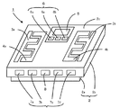
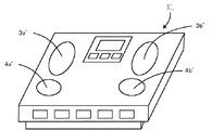
図1に示すように、この体組成測定装置1は、その本体2が基台2aとこの基台2aに載置された載台2bとから構成されており、載台2bの上面2cには、使用者の身体の2部位としての左右の足裏間に交流電流を流すための通電電極3a、3bと、このときに左右の足裏間に生じる電圧(電位差)を測定するための測定電極4a、4bと、この体組成測定装置1で測定された体組成の表示等に用いる公知の液晶画面等からなる表示装置5と、使用者が性別、年齢、身長等の個人データを入力するための入力装置6とが配設されている。ここで、載台2bの上面2cは樹脂製であり、通電電極3a、3bと測定電極4a、4bとは、上面 2cにおいて互いに絶縁されている。また、入力装置6は、入力データの選択操作等に用いる選択キー6a、6bと、入力データの決定操作等に用いる決定キー6cとを含んでいる。また、本体2の側面には、既に入力済みの個人データがある場合にこれを呼出すための4つのキー7a、7b、7c、7dからなる個人キー7と、電源キー8とが配設されている。
As shown in FIG. 1, the body
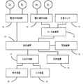
また、図2に示すように、この体組成測定装置1の本体2の内部には、前記通電電極3a、3bに接続された電流供給回路9と、前記測定電極4a、4bに接続された電圧測定回路10と、荷重に応じた電圧を出力することにより使用者の体重を測定するための重量センサ11と、これら電圧測定回路10及び重量センサ11からの電圧信号をデジタル変換するA/D変換器12と、前記表示装置5及び前記入力装置6に接続された入出力回路13と、入力された個人データ、測定された体重、測定された体組成を記憶させるための記憶装置14と、電池を含む電源装置15と、これら電流供給回路9、A/D変換器12、入出力回路13、記憶装置14及び電源装置15に電気的に接続された制御装置16とが配設されている。
Further, as shown in FIG. 2, the
このような構成において、制御装置16は、公知の演算素子(CPU)を含み、記憶装置14に予め記憶された制御プログラムを実行することにより、通電電極3a、3bに交流電流を供給する制御、この電流値と測定電極4a、4bで検出される電圧値とに基づいて使用者の生体電気インピーダンスを算出する制御、この生体電気インピーダンスと入力装置6で入力された使用者の個人データと重量センサ11で測定された使用者の体重とから使用者の体組成を算出する制御、入力された個人データ、測定された体重、算出された体組成を表示装置5に表示し、及び記憶装置14に記憶させる制御等、各種の制御処理を実行し、以って使用者の体組成を測定するものである。尚、これらの制御処理については、従来公知の体組成測定装置と変わるところがないので、これ以上の説明は割愛する。
In such a configuration, the
本発明の実施例たる体組成測定装置1の特徴的な構成は、その電極の配設構造にある。まず、通電電極3aと測定電極4aとは、使用者の左足裏に接触するように、対をなして本体2の上面2cに配設されている。そして、これらの電極3a、4aは、夫々が上面視で櫛形に形成され、互いにその歯部31a、32a、41a、42a、43a(図3参照)を噛合せるように対向して配設されている。同様に、通電電極3bと測定電極4bとは、使用者の右足裏に接触するように、対をなして本体2の上面2cに配設され、夫々が上面視で櫛形に形成され、互いにその歯部を噛合せるように対向して配設されている。
The characteristic composition of the body
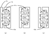
使用者は、体組成を測定するため、上述の如く配設された電極3a、4a及び電極3b、4bに左右夫々の足裏を接触させて本体2の上面2cに立つわけであるが、このときの立ち位置は、図3に示すように測定の度にずれる可能性がある。図3において、破線で描かれた楕円は、使用者の左足が乗せられた領域を模式的に表すものであり、各電極3a、4aは、この楕円の内側と重なる部分で、使用者の左足裏と接触している。即ち、図3(a)は、使用者の左足が電極配列の略中央に乗せられた状態を示しており、図3(b)は立ち位置が前方にずれた状態を、図3(c)は立ち位置が後方にずれた状態を示している。
In order to measure the body composition, the user stands on the upper surface 2c of the
ここで、通電電極3aは、図3(a)から(c)の何れの場合においても、測定電極4aと足裏との接触点を含む歯部42aを挟んで配設された歯部31aと歯部32aとにおいて、足裏と接触している。即ち、通電電極3aと足裏との接触面積は、図3(a)から(c)の何れの場合においても、略同等であるということができる。
Here, in any case of FIGS. 3A to 3C, the energizing
一方、測定電極4aは、図3(a)の場合は歯部41aの一部と歯部42aと歯部43aの一部とにおいて、図3(b)の場合は歯部41aの大部分と歯部42aとにおいて、図3(c)の場合は歯部42aと歯部43aの大部分とにおいて、夫々足裏と接触している。即ち、測定電極4aと足裏との接触面積も、図3(a)から(c)の何れの場合においても、略同等であるということができる。尚、歯部41aと歯部42aは、通電電極3aと足裏との接触点を含む歯部31aを挟んで配設されており、歯部42aと歯部43aとは、通電電極3aと足裏との接触点を含む歯部32aを挟んで配設されている。
On the other hand, the
通電電極3a及び測定電極4aの配設構造は上述の通りであるが、これと同様の配設構造が、右足裏に接触する通電電極3b及び測定電極4bにおいても採用されている。
The arrangement structure of the
上述のように、この体組成測定装置1では、身体の2部位としての両足裏間に通電するための一組の通電電極3a、3bと、両足間の電位差を測定するための一組の測定電極4a、4bと、これら複数の電極3a、3b、4a、4bが互いに絶縁して配設された上面2cを有する本体2とを備え、前記一組の通電電極3a、3bの夫々が、前記測定電極と足裏との接触点(例えば、歯部42aに含まれる点)を挟む複数の点(例えば、歯部31aに含まれる点と歯部32aに含まれる点)で足裏と接触し、且つ、前記一組の測定電極4a、4bの夫々が、前記通電電極と足裏との接触点(例えば、歯部31aに含まれる点、又は歯部32aに含まれる点)を挟む複数の点(例えば、歯部41aに含まれる点と歯部42aに含まれる点、又は歯部42aに含まれる点と歯部43aに含まれる点)で足裏と接触するように、前記本体2の上面2cに配設されている。この結果、図3(a)から(c)の如く足裏の接触位置がずれたとしても、各電極と足裏との接触面積全体は大きく変わらず、接触面積のバラツキが低減されるものである。
As described above, in this body
図4及び図5には、本発明の様々な実施の形態が模式的に表されている。 4 and 5 schematically show various embodiments of the present invention.
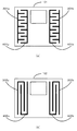
図4(a)の体組成測定装置101では、前記体組成測定装置1の場合と同様に、上面視で櫛形に形成された通電電極301a、301bと測定電極401a、401bとが用いられているが、体組成測定装置1に比して歯部の数が増やされている。歯部の数が増えた分、接触位置のずれを更に効果的に吸収して接触面積のバラツキを抑え得るものである。
In the body
図4(b)の体組成測定装置102では、通電電極302a、302bと測定電極402a、402bとは、足の長さ方向に櫛形とされている。電極を足裏に接触させるタイプの体組成測定装置では、立ち位置は足の長さ方向にずれることが多いと考えられるので、足の長さ方向に延びる歯部を備えた櫛形電極であれば、立ち位置のずれによる接触位置のずれを更に効果的に吸収して接触面積のバラツキを抑え得るものである。
In the body
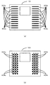
図5(a) の体組成測定装置103では、通電電極303a、303bと測定電極403a、403bとが、夫々が本体の上面において独立した複数の棒形の小片電極として、交互に配設されている。もちろん、通電電極としての各小片電極303a、303bは、夫々が本体の内部において電気的に接続されており、図2の通電電極3a、3bと同様に電流供給回路に接続されている。また、測定電極としての各小片電極403a、403bも、夫々が本体の内部において電気的に接続されており、図2の測定電極4a、4bと同様に電圧測定回路に接続されている。
In the body
図5(b)の体組成測定装置104では、通電電極304a、304b(図中、白丸)と測定電極404a、404b(図中、黒丸)とが、夫々が本体の上面において独立した複数の円形の小片電極として、交互に配設されている。もちろん、通電電極としての各小片電極303a、303bは、夫々が本体の内部において電気的に接続されており、図2の通電電極3a、3bと同様に電流供給回路に接続されている。また、測定電極としての各小片電極403a、403bも、夫々が本体の内部において電気的に接続されており、図2の測定電極4a、4bと同様に電圧測定回路に接続されている。尚、図中における白丸黒丸の色分けは便宜上のものであって、このような色分けが必須ということではない。
In the body
図5(a)、(b)の如く電極を小片電極で構成することで、接触位置のずれを更に効果的に吸収して接触面積のバラツキを抑え得るものである。 By configuring the electrodes with small pieces as shown in FIGS. 5A and 5B, the displacement of the contact position can be more effectively absorbed and the variation of the contact area can be suppressed.
本発明の効果を確認するため、本願出願人は、年齢、身長、体重、足サイズの異なる3名の使用者A、B、Cについて、図4(a)の如く多数の歯部を備えた櫛形電極301a、301b、401a、401bが配設された体組成測定装置101と、図6に示す如く足先側に配設された通電電極3a’、3b’及び踵側に配設された測定電極4a’、4b’を備えた従来公知の体組成測定装置1’とを用い、体脂肪率の測定バラツキに関する比較試験を行った。
In order to confirm the effect of the present invention, the applicant of the present application provided a large number of teeth as shown in FIG. 4 (a) for three users A, B, and C having different ages, heights, weights, and foot sizes. Body
比較試験において、各使用者A、B、Cは、夫々が各体組成測定装置を用いて、図3の如く電極配列の略中央、前方、後方の3種類の立ち位置で体脂肪率の測定を行った。使用者Aが従来公知の体組成測定装置1’を用いて測定した3種類の体脂肪率は、最大値が22.4%、最小値が21.4%であり、その最大最小差(最大値−最小値)は1ポイントであった。一方、この使用者Aが本発明による体組成測定装置101を用いた場合の最大最小差は0.1ポイントであった。同様に、使用者Bが従来公知の体組成測定装置1’を用いた場合の最大最小差は0.7ポイント、本発明による体組成測定装置101を用いた場合の最大最小差は0.4ポイントであった。同様に、使用者Cが従来公知の体組成測定装置1’を用いた場合の最大最小差は0.7ポイント、本発明による体組成測定装置101を用いた場合の最大最小差は0.2ポイントであった。このように、本発明の体組成測定装置によれば、立ち位置がずれることによって身体と電極との接触位置にバラツキが生じても、測定結果のバラツキが大きく抑えられていることが確認された。
In the comparative test, each user A, B, and C uses each body composition measuring device to measure the body fat percentage at three types of standing positions in the approximate center, front, and back of the electrode array as shown in FIG. Went. The three types of body fat percentages measured by the user A using the conventionally known body
以上、本発明及びその実施の形態について詳述してきたが、本発明は、以上の説明に限定されることなく、特許請求の範囲に記載した構成を備える限りにおいて、様々な変形が可能である。即ち、各電極の形状や配列は図4、図5に示した以外の形状や配列としてもよく、また、本発明は、使用者の足裏に電極を接触させるタイプの体組成測定装置に適用するだけでなく、掌に電極を接触させるタイプや、掌と足裏の両方に電極を接触させるタイプ、或いは、手足以外の身体部位に電極を接触させるタイプ等、様々なタイプの体組成測定装置に適用することが可能である。 The present invention and the embodiments thereof have been described in detail above, but the present invention is not limited to the above description, and various modifications are possible as long as the configuration described in the claims is provided. . That is, the shape and arrangement of each electrode may be other than those shown in FIGS. 4 and 5, and the present invention is applied to a body composition measuring apparatus of a type in which an electrode is in contact with the sole of a user. Various types of body composition measuring devices, such as a type in which the electrode is brought into contact with the palm, a type in which the electrode is brought into contact with both the palm and the sole, and a type in which the electrode is brought into contact with a body part other than the limb It is possible to apply to.
1 体組成測定装置
2 本体
2a 基台
2b 載台
2c 上面
3a、3b 通電電極
4a、4b 測定電極
31a、32a、41a、42a、43a 歯部
5 表示装置
6 入力装置
6a、6b 選択キー
6c 決定キー
7(7a、7b、7c、7d) 個人キー
8 電源キー
9 電流供給回路
10 電圧測定回路
11 重量センサ
12 A/D変換器
13 入出力回路
14 記憶装置
15 電源装置
16 制御装置
101、102、103、104、 体組成測定装置
301a、301b、302a、302b、303a、303b、304a、304b 通電電極
401a、401b、402a、402b、403a、403b、404a、404b 測定電極
1’ 従来の体組成測定装置
3a’、3b’ 通電電極
4a’、4b’ 測定電極
DESCRIPTION OF
Claims (6)
前記複数の電極は、前記一組の通電電極の夫々が前記測定電極と身体との接触点を挟む複数の点で身体と接触し、且つ、前記一組の測定電極の夫々が前記通電電極と身体との接触点を挟む複数の点で身体と接触するように、前記本体の面に配設されていることを特徴とする体組成測定装置。 At least one set of energizing electrodes for energizing between two parts of the user's body, at least one set of measuring electrodes for measuring a potential difference between the two parts, and the plurality of electrodes are insulated from each other. A body composition measuring device comprising a body having a provided surface,
Each of the plurality of electrodes is in contact with the body at a plurality of points sandwiching a contact point between the measurement electrode and the body, and each of the pair of measurement electrodes is connected to the conduction electrode. The body composition measuring device is arranged on the surface of the main body so as to come into contact with the body at a plurality of points sandwiching the contact point with the body.
5. The body composition measuring apparatus according to claim 4, wherein the small piece electrode has a rod shape when viewed from above.
Priority Applications (4)
| Application Number | Priority Date | Filing Date | Title |
|---|---|---|---|
| JP2004118269A JP2005296415A (en) | 2004-04-13 | 2004-04-13 | Body composition measuring device |
| EP05007409A EP1586267A1 (en) | 2004-04-13 | 2005-04-05 | Body composition measuring apparatus |
| US11/100,412 US20050228449A1 (en) | 2004-04-13 | 2005-04-07 | Body composition measuring apparatus |
| CNB2005100651732A CN100377688C (en) | 2004-04-13 | 2005-04-13 | body composition measurement device |
Applications Claiming Priority (1)
| Application Number | Priority Date | Filing Date | Title |
|---|---|---|---|
| JP2004118269A JP2005296415A (en) | 2004-04-13 | 2004-04-13 | Body composition measuring device |
Publications (2)
| Publication Number | Publication Date |
|---|---|
| JP2005296415A true JP2005296415A (en) | 2005-10-27 |
| JP2005296415A5 JP2005296415A5 (en) | 2007-05-10 |
Family
ID=34934772
Family Applications (1)
| Application Number | Title | Priority Date | Filing Date |
|---|---|---|---|
| JP2004118269A Pending JP2005296415A (en) | 2004-04-13 | 2004-04-13 | Body composition measuring device |
Country Status (4)
| Country | Link |
|---|---|
| US (1) | US20050228449A1 (en) |
| EP (1) | EP1586267A1 (en) |
| JP (1) | JP2005296415A (en) |
| CN (1) | CN100377688C (en) |
Cited By (1)
| Publication number | Priority date | Publication date | Assignee | Title |
|---|---|---|---|---|
| JP2008284354A (en) * | 2007-05-21 | 2008-11-27 | Biospace Co Ltd | Biological impedance measuring apparatus |
Families Citing this family (8)
| Publication number | Priority date | Publication date | Assignee | Title |
|---|---|---|---|---|
| KR100624446B1 (en) * | 2004-11-06 | 2006-09-15 | 삼성전자주식회사 | Body fat measurement method and a suitable device |
| DE102006026281B3 (en) * | 2006-06-02 | 2007-11-29 | Medisana Ag | Weighing device for measuring the bodyweight, water content, muscle and bone density of a person comprises light sources arranged inside or outside a translucent plate |
| US10130273B2 (en) | 2014-06-12 | 2018-11-20 | PhysioWave, Inc. | Device and method having automatic user-responsive and user-specific physiological-meter platform |
| US9949662B2 (en) | 2014-06-12 | 2018-04-24 | PhysioWave, Inc. | Device and method having automatic user recognition and obtaining impedance-measurement signals |
| US9943241B2 (en) | 2014-06-12 | 2018-04-17 | PhysioWave, Inc. | Impedance measurement devices, systems, and methods |
| EP3154427A4 (en) * | 2014-06-12 | 2018-03-14 | Physiowave, Inc. | Impedance measurement devices, systems, and methods |
| KR20170114615A (en) * | 2016-04-05 | 2017-10-16 | 엘지전자 주식회사 | Mobile terminal and method of controlling the same |
| EP3943003A4 (en) * | 2019-03-19 | 2022-06-22 | Toray Engineering Co., Ltd. | Muscle fatigue evaluation method and muscle fatigue evaluation system |
Citations (6)
| Publication number | Priority date | Publication date | Assignee | Title |
|---|---|---|---|---|
| JPH0380748U (en) * | 1989-12-06 | 1991-08-19 | ||
| JPH10272112A (en) * | 1997-04-01 | 1998-10-13 | Sekisui Chem Co Ltd | Human body electrical characteristics measurement device |
| JP2000237254A (en) * | 1999-02-22 | 2000-09-05 | Ya Man Ltd | Foot sole massaging device having body fat measuring function |
| JP2002345774A (en) * | 2001-05-29 | 2002-12-03 | Tanita Corp | Biometric device with measurer determination function |
| EP1336825A2 (en) * | 2002-02-13 | 2003-08-20 | Soehnle-Waagen GmbH & Co. KG | Apparatus for analysing body weight |
| JP2004195220A (en) * | 2002-12-14 | 2004-07-15 | Research Inst Of Tsinghua Univ In Shenzhen | Human body composition monitoring method and instrument for measuring induction coefficient and impedance of human body by digital quantity sampling method of frequency |
Family Cites Families (10)
| Publication number | Priority date | Publication date | Assignee | Title |
|---|---|---|---|---|
| JP2514259Y2 (en) * | 1991-03-29 | 1996-10-16 | 株式会社タニタ | Body fat meter |
| US5415176A (en) * | 1991-11-29 | 1995-05-16 | Tanita Corporation | Apparatus for measuring body fat |
| DE19530092A1 (en) * | 1995-08-16 | 1997-02-20 | Daimler Benz Ag | Checkable film pressure sensor |
| JP2001078978A (en) * | 1999-09-09 | 2001-03-27 | Omron Corp | Health management guide advice device |
| US6292690B1 (en) * | 2000-01-12 | 2001-09-18 | Measurement Specialities Inc. | Apparatus and method for measuring bioelectric impedance |
| JP2001228013A (en) * | 2000-02-16 | 2001-08-24 | Tanita Corp | Biological measuring device with weight scale |
| DE20116409U1 (en) * | 2000-09-30 | 2002-01-24 | Fook Tin Plastic Factory Ltd., Quarry Bay | Body fat measuring device |
| CN2529252Y (en) * | 2002-02-28 | 2003-01-01 | 陈智裕 | body fat scale |
| JP4105472B2 (en) * | 2002-04-12 | 2008-06-25 | 株式会社フィジオン | Body composition measuring device |
| US6850798B2 (en) * | 2002-10-08 | 2005-02-01 | Nestec, Ltd. | Method and apparatus for measuring body fat in animals |
-
2004
- 2004-04-13 JP JP2004118269A patent/JP2005296415A/en active Pending
-
2005
- 2005-04-05 EP EP05007409A patent/EP1586267A1/en not_active Withdrawn
- 2005-04-07 US US11/100,412 patent/US20050228449A1/en not_active Abandoned
- 2005-04-13 CN CNB2005100651732A patent/CN100377688C/en not_active Expired - Fee Related
Patent Citations (6)
| Publication number | Priority date | Publication date | Assignee | Title |
|---|---|---|---|---|
| JPH0380748U (en) * | 1989-12-06 | 1991-08-19 | ||
| JPH10272112A (en) * | 1997-04-01 | 1998-10-13 | Sekisui Chem Co Ltd | Human body electrical characteristics measurement device |
| JP2000237254A (en) * | 1999-02-22 | 2000-09-05 | Ya Man Ltd | Foot sole massaging device having body fat measuring function |
| JP2002345774A (en) * | 2001-05-29 | 2002-12-03 | Tanita Corp | Biometric device with measurer determination function |
| EP1336825A2 (en) * | 2002-02-13 | 2003-08-20 | Soehnle-Waagen GmbH & Co. KG | Apparatus for analysing body weight |
| JP2004195220A (en) * | 2002-12-14 | 2004-07-15 | Research Inst Of Tsinghua Univ In Shenzhen | Human body composition monitoring method and instrument for measuring induction coefficient and impedance of human body by digital quantity sampling method of frequency |
Cited By (1)
| Publication number | Priority date | Publication date | Assignee | Title |
|---|---|---|---|---|
| JP2008284354A (en) * | 2007-05-21 | 2008-11-27 | Biospace Co Ltd | Biological impedance measuring apparatus |
Also Published As
| Publication number | Publication date |
|---|---|
| EP1586267A1 (en) | 2005-10-19 |
| US20050228449A1 (en) | 2005-10-13 |
| CN100377688C (en) | 2008-04-02 |
| CN1682655A (en) | 2005-10-19 |
Similar Documents
| Publication | Publication Date | Title |
|---|---|---|
| JP4074236B2 (en) | Body composition information acquisition device | |
| JP5990820B2 (en) | Biometric apparatus and body image creation program | |
| KR102335768B1 (en) | Apparatus and method for measuring body fat | |
| KR100427625B1 (en) | Dividable type apparatus for measuring living body impedance | |
| US20100312148A1 (en) | Posture evaluating apparatus | |
| JP2005296415A (en) | Body composition measuring device | |
| KR0123408B1 (en) | Method and apparatus for determining body composition using bioelectrical impedance analysis | |
| EP1092388B1 (en) | Body composition measuring apparatus with built-in weight meter | |
| US20060206271A1 (en) | Body composition measuring apparatus | |
| JP2005000565A (en) | Biological information acquisition device | |
| JP2002065629A (en) | Bioimpedance measurement device | |
| KR100423678B1 (en) | Bioelectrical impedance measuring apparatus with handgrip | |
| JP2001078978A (en) | Health management guide advice device | |
| EP1479339B1 (en) | Method and apparatus for estimation of muscle mass | |
| CN109998498A (en) | Electronic equipment | |
| KR101206610B1 (en) | Apparatus for body composition measurement having detachable supporter | |
| JP2005125059A (en) | Body fat scale and body fat percentage estimation program | |
| JP4065062B2 (en) | Body fat percentage measuring instrument | |
| JP2003169784A (en) | Body fat measurement device | |
| JP4422997B2 (en) | Disease recovery state determination device and program | |
| JP5030659B2 (en) | Body composition meter | |
| JP2011191088A (en) | Load meter | |
| JP3508633B2 (en) | Body fat scale | |
| KR200361600Y1 (en) | Foot electrodes of analyzing body fat meter | |
| KR100819537B1 (en) | Body composition analyzer with body temperature measurement |
Legal Events
| Date | Code | Title | Description |
|---|---|---|---|
| A521 | Request for written amendment filed |
Free format text: JAPANESE INTERMEDIATE CODE: A523 Effective date: 20070313 |
|
| A621 | Written request for application examination |
Free format text: JAPANESE INTERMEDIATE CODE: A621 Effective date: 20070313 |
|
| A977 | Report on retrieval |
Free format text: JAPANESE INTERMEDIATE CODE: A971007 Effective date: 20091029 |
|
| A131 | Notification of reasons for refusal |
Free format text: JAPANESE INTERMEDIATE CODE: A131 Effective date: 20100317 |
|
| A02 | Decision of refusal |
Free format text: JAPANESE INTERMEDIATE CODE: A02 Effective date: 20100805 |