JP2005296322A - Hook - Google Patents
Hook Download PDFInfo
- Publication number
- JP2005296322A JP2005296322A JP2004116655A JP2004116655A JP2005296322A JP 2005296322 A JP2005296322 A JP 2005296322A JP 2004116655 A JP2004116655 A JP 2004116655A JP 2004116655 A JP2004116655 A JP 2004116655A JP 2005296322 A JP2005296322 A JP 2005296322A
- Authority
- JP
- Japan
- Prior art keywords
- cylinder
- hook
- guide
- fixed hook
- fixed
- Prior art date
- Legal status (The legal status is an assumption and is not a legal conclusion. Google has not performed a legal analysis and makes no representation as to the accuracy of the status listed.)
- Granted
Links
- 239000002184 metal Substances 0.000 abstract description 2
- 208000008918 voyeurism Diseases 0.000 abstract 1
- 239000000853 adhesive Substances 0.000 description 4
- 230000001070 adhesive effect Effects 0.000 description 4
- 210000001061 forehead Anatomy 0.000 description 2
- 230000002093 peripheral effect Effects 0.000 description 2
- 238000013459 approach Methods 0.000 description 1
- 230000006835 compression Effects 0.000 description 1
- 238000007906 compression Methods 0.000 description 1
- 230000007423 decrease Effects 0.000 description 1
- 230000001771 impaired effect Effects 0.000 description 1
- 239000000463 material Substances 0.000 description 1
- 239000011150 reinforced concrete Substances 0.000 description 1
- 238000009423 ventilation Methods 0.000 description 1
Images


Landscapes
- Mirrors, Picture Frames, Photograph Stands, And Related Fastening Devices (AREA)
Abstract
Description
この発明は、主として大型の額入りの書画などを室内の壁面に掛けるためのフックに関するもので、視認できない裏側に額の背面両側に繋いだ吊紐を掛けて放すと額の重量がトリガーとなって、フックを被う誘導片が壁面に近付き確実に止められるようにするものである。 The present invention mainly relates to a hook for hanging a large framed document or the like on a wall surface in a room. When a hanging strap connected to both sides of the back of the forehead is hung and released on the back side, the weight of the forehead becomes a trigger. Thus, the guide piece covering the hook approaches the wall surface and is surely stopped.
従来の壁面に額縁を掛け止めるためのフックは、壁面への取付板に両面接着剤を備えたフックを接着するか、壁面にねじ込むねじ棒を備えたフックが知られており、これらのフックを壁面に予め取り付け、額縁の吊紐を掛けていた。
特許文献1には、吊紐のずれを防止するための手段が提案されているが、フック自体は従来の構成のままである。
従来のフックでは、鍵形の突き出しが少ないために、額縁の裏面となる吊紐を掛けるのが困難であった。特に壁面の高い箇所に掛けるには、別途二股の金具を先端に備えた棒に吊紐を掛けて額縁の横から壁の後ろを覗き込み引っ掛けることになっていた。
さらには、掛ける額縁の重量により時の経過とともに接着剤を塗布したフックでは粘着力が弱まり、また、ねじ棒を備えたフックでは長さ及び太さにもよるが、地震などで緩んで落下する恐れがあった。
In the conventional hook, since there is little protrusion of a key shape, it was difficult to hang the hanging strap used as the back surface of a frame. In particular, in order to hang on a high part of the wall surface, a hanging string was hung on a bar with a separate bifurcated bracket at the tip, and the back of the wall was looked from the side of the frame and hooked.
Furthermore, the adhesive strength of a hook with adhesive applied decreases with the passage of time due to the weight of the frame to be hung, and the hook with a threaded rod falls loosely due to an earthquake, etc., depending on the length and thickness. There was a fear.
この発明は、このような従来技術の課題を解決すべく開発したもので、固定フックの上部にスライドして接離自在なスライドフックを配置することで、フックに額縁を掛ける前は一時的に両フックで奥行きを広くして容易に吊紐を掛け易くし、額縁の位置を調整してから固定フックに重量を掛けることでスライドフックが固定フックの上部を被い吊紐を外れないようにしたものである。
請求項1の発明に係るフックFは、取付フランジの一方側に内壁に穿った溝穴に押し込む外筒と、取付フランジ他方側には、つき合わせて組み付ける上筒及び中筒を配し、上筒には作動筒の外周に密着し取付フランジから外筒内に至る案内筒を固着してあり、作動筒に外嵌させ一端を止めたコイルバネを案内筒の開放端に当接させ、作動筒を引き出すことで付勢するようにし、案内筒に固定フック付リングをはめ中筒から覗くようにし、固定フック付リングの内向き掛合突起が案内筒の案内溝から作動筒の凹状掛止部に入り込むように付勢して引き出された作動筒を掛止し、フックを押圧することで解除し作動筒がコイルバネの作用で外筒の奥に入り込むようにし、作動筒の端部には固定フック側に倒伏しそこから折り起し自在なスライドフックを設けたことを特徴とするものである。
The present invention has been developed to solve such problems of the prior art, and by placing a slide hook that slides on top of the fixed hook and can be freely contacted and separated, it is temporarily before the frame is hung on the hook. Both hooks have a wider depth to make it easier to hang the hanging strap. Adjust the position of the frame and then hang the weight on the fixed hook so that the slide hook covers the upper part of the fixed hook and does not come off the hanging strap. It is what.
The hook F according to the invention of
請求項1の発明では、作動筒によりスライドフックが突出することになるので、簡単に額縁裏面の吊紐を掛けることができ、このスライドフックは額縁の自重により作動筒が壁内に移動してスライドフックが固定フックを被うことになり壁面近くに設置できることになる。そこで、一人でも壁面のフックに重い額縁を掛けることができることになる。
また、額縁に限らず、狭い場所や手の届かない場所であっても物を掛ける場合にフックが手前に出ているので掛け易くなるのである。
スライドフックは、折り起し自在な構成としてあるので、外す場合は、吊紐を持ち上げると難なく外れることになる。
In the invention of
Further, not only in the frame, but also in a narrow place or a place out of reach, when hooking an object, the hook comes out to the front so that it is easy to hang.
Since the slide hook is configured to be foldable, it can be removed without difficulty by lifting the hanging strap.
以下図面に示すこの発明の実施の形態に即して説明する。
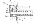
このフックFは概略、取付フランジ1の一方側に内壁Wに穿った溝穴Hに押し込む外筒2と、取付フランジ1他方側には、つき合わせて組み付ける上筒3及び中筒4を配し、上筒3には作動筒5の外周に密着し取付フランジ1から外筒2内に至る案内筒6を固着してあり、作動筒5に外嵌させ一端を止めたコイルバネ7を案内筒6の開放端に当接させ、作動筒5を引き出すことで付勢するようにし、案内筒6に固定フック付リング8をはめ中筒4から覗くようにし、固定フック付リング8の内向き掛合突起81が案内筒6の案内溝61から作動筒5の凹状掛止部55に入り込むように付勢して引き出された作動筒5を掛止し、固定フック付リング8を押圧することで解除し、作動筒5がコイルバネ7の作用で外筒2の奥に入り込むようにし、作動筒5の端部には固定フック側に倒伏しそこから折り起し自在なスライドフックF2を設けたことを特徴とするものである。
The present invention will be described below with reference to the embodiments shown in the drawings.
The hook F is roughly arranged with an
取付フランジ1中央の丸穴11には穴縁に段縁11aを設け、この段縁11aに外筒2の上端縁を嵌め込むようにしてある。
The
上筒3は、中筒4と同一径の短筒31と鍔つきの案内筒6と分離しているが、短筒31と案内筒6を接合させて一体としてから組み付けるようにする。なお、予め一体として成形するようにしてもよい。
上筒3は一方端に環状の当接部31aを備え、当接部31a側の周端より垂片31bを連設するようにしてあり、案内筒6には周側に案内溝61を設け、案内溝61は垂片31bと向き合うようにしてある。案内筒6の内径と作動筒5の外径とほぼ一致するようにして、作動筒5がスムースにスライドできるようにしてある。
31cは当接部31a上に配置したクッションであり、作動筒5が外筒2内に入って作動筒5のフランジ51が衝突したときの衝撃を緩和するためのものである。
The
The
31c is a cushion disposed on the
中筒4は、一端より角形の窓穴41を設けてあり、他端には取付フランジ1の丸穴11周縁への環状の当接部42を設けるようにしてある。この中筒4は取付フランジ1に取り付けるのであるが、中筒4の当接部42にピン43を植設し、取付フランジ1の丸穴41を中にした対向位置の小孔12、12にピン43、43を差し込み取り付けるようにしてある。ピン43及び小孔12は適宜増やすことができる。
The
作動筒5は、上筒3、中筒4を通して案内筒6に挿入して掛止させ摺動するもので、一端を塞ぐキャップ51を備え、このキャップ51に固定フックF1の上部に接離するスライドフックF2を設けてある。
スライドフックF2は、キャップ51に沿わせた起立板52a及び固定フックF1の側端に傾斜して近接して、かつ、固定フックF1上を被う回動板52bを跳ね上げ可能に繋げてなるものである。具体的には、起立板52aと回動板52bはピン52cで連結し、固定フックF1への傾斜状態を保つためにストッパー52dを設けるようにしてある。
作動筒5の胴部外周には、案内筒6の案内溝61に入り込む方形突起54及び固定フック付リング8の掛合突起81の先端を受け入れる凹状掛止部55(図2、図3参照)を設けるようにしてあり、胴部の端部には周溝56を設け、この周溝56にコイルバネ7の一端部を止める止輪57を嵌め込むようにしてある。
The
The slide hook F2 is connected to the
On the outer periphery of the barrel portion of the working
上筒3を、中筒4の窓穴41がほぼ矩形となるよう組み付けて、この窓穴41より固定フック付リング8の固定フックF1が上部に覗くようにしてある。
上筒3には予め径が細く作動筒5の外周に密着し取付フランジ1から外筒2内に至る案内筒6を固定し、案内筒6と作動筒5の間には、弾性手段として作動筒3に外嵌させるコイルバネ91及び掛止手段としては固定フック付リング8とからなる駆動機構を組み込むようにしてある。
The
The
案内筒6に遊嵌する固定フック付リング8は、固定フックF1の基部となる内周に凹部82を設け、凹部82と向き合う内周に掛合突起81を形成してある。固定フックF1付リング8の掛合突起81を案内筒6の案内溝61に合わせ、凹部82と案内筒6との間にはバネ83を縮装して収納する。固定フック付リング8はバネ8dにより付勢され固定フックF1が窓穴41から上部に覗き、掛合突起81が作動筒5の外周に押し付けられることになる。
そして、作動筒5を引き出したときに凹状掛止部55に、固定フック付リング8の掛合突起81に入り込んで止まり、作動筒5のスライドフックF2が傾斜して固定フックF1側への案内路となる(図2参照)。
The
Then, when the
この状態ではフックFは、固定フックF1とスライドフックF2で内壁Wより前面に突出するので、額縁(図示せず)の吊紐Rが掛け易くなる。
位置決めしてから額縁を降ろして吊紐Rで固定フックF1に荷重を掛けると作動筒5の凹状掛止部55への固定フック付リング8の掛合突起81の掛止が外れ、圧縮されていたコイルバネ7が開放され、作動筒5が案内筒6を介して外筒2内に入り込み、スライドフックF2が固定フックF1上を被うことになる。
In this state, the hook F protrudes from the inner wall W to the front surface by the fixed hook F1 and the slide hook F2, so that the hanging strap R of the frame (not shown) can be easily hung.
After the positioning, the frame is lowered and a load is applied to the fixed hook F1 by the hanging strap R, and the
組み付ける際は、まず、スライドフックF2を一体に組み付けた作動筒5を、案内筒6を一体に取り付けた上筒3に挿入する。このとき、案内筒6の案内溝61に、作動筒5の方形突起54が入り込むようにする。そしてコイルバネ7を作動筒5外周より入れ、止輪57によりコイルバネ7を止めるようにする。コイルバネ7は案内筒6の開放端62と止輪57により両端を拘束され、作動筒5を摘んで引き出すことにより圧縮され付勢されることになる。
この状態で固定フック付リング8の掛合突起81を案内筒6の案内溝61に合わせ、固定フック付リング8の凹部92bと他方の案内溝71の間にバネ83を押し込むようにする。固定フック付リング8の固定フックF1は水平に配置されることになる。
一方、外筒2を取付フランジ1の丸穴11周囲の段縁11aに嵌め込み固定しておく。 そして、取付フランジ1中央の丸穴11より作動筒5、案内筒6を挿入し、中筒4のピン43、43を取付フランジ1の小孔12、12に嵌め込んで組立が完了するのである。
なお、組み立てる場合は必要に応じて接着剤を塗布して簡単に外れないようにすることが望ましい。
When assembling, first, the
In this state, the hooking
On the other hand, the
When assembling, it is desirable to apply an adhesive as necessary so that it does not come off easily.
作動筒5を掴んで引き出すことによりコイルバネ7が圧縮されが、固定フックF1付リング8の掛合突起81はバネ83により内側に付勢されているので、作動筒5の凹状掛止部55に入り込み、作動筒5が停止することになる。
The
固定フックF1に額縁を掛けて重量を掛けると固定フック付リング8の掛合突起81と作動筒5の凹状掛止部55との掛合状態を解除し、縮装付勢されているコイルバネ7の一端部が案内筒6の開放端62に当接しているので、スライドフックF2と一体となった作動筒5が瞬時に外筒2に入り込み、固定フックF1に被さることになる。
When the frame is hung on the fixed hook F1 and the weight is applied, the engagement state between the
このフックFを用いるには予め内壁Wに溝穴Hを穿つのであるが、溝穴H内に長尺のナットを埋設し、外筒2外周にネジを切っておくことによりねじ込むようにしてもよい。内壁Wに穿った溝穴Hは用いないときにはキャップで蓋をしておくようにして体裁を損なわないようにする。詳細な図示は省略したが、取付フランジ1から複数の止めねじを内壁Wにねじ込むようにしてもよい。
基本的な素材については、プラスチックの成形品、金属製など適宜選択することができるが、吊り下げる物品によって、大きさ、強度、構成を変更することができる。
In order to use this hook F, a slot H is drilled in the inner wall W in advance, but a long nut is embedded in the slot H and the
The basic material can be selected as appropriate, such as a plastic molded product or metal, but the size, strength, and configuration can be changed depending on the article to be hung.
このフックは、吊紐で掛ける額縁に幻影されず、例えば、カーテンレールの両端をこのフックで支え、カーテンレールの壁面への当接面を接着するなどして取り付けることもできる。同様に配線、配管のためのレールとすることもできる。
さらには、室内用壁掛けタイプの換気扇やエアコンディショナーなどのように重量があっても壁面に掛けることができる。
ビルの外壁や体育館その他鉄筋コンクリート建築物の内外に用いることができる。
The hook is not illusioned on the frame hung by the hanging strap, and can be attached by, for example, supporting both ends of the curtain rail with the hook and bonding the contact surface to the wall surface of the curtain rail. Similarly, rails for wiring and piping can be used.
Furthermore, it can be hung on a wall surface even if it is heavy, such as an indoor wall-mounted ventilation fan or air conditioner.
It can be used on the exterior and exterior of buildings, gymnasiums and other reinforced concrete buildings.
F フック
F1 固定フック
F2 スライドフック
1 取付フランジ
2 外筒
3 上筒
4 中筒
5 作動筒
6 案内筒
7 コイルバネ
8 固定フック付リング
F hook F1 fixed hook
Claims (1)
Priority Applications (1)
| Application Number | Priority Date | Filing Date | Title |
|---|---|---|---|
| JP2004116655A JP3921207B2 (en) | 2004-04-12 | 2004-04-12 | hook |
Applications Claiming Priority (1)
| Application Number | Priority Date | Filing Date | Title |
|---|---|---|---|
| JP2004116655A JP3921207B2 (en) | 2004-04-12 | 2004-04-12 | hook |
Publications (2)
| Publication Number | Publication Date |
|---|---|
| JP2005296322A true JP2005296322A (en) | 2005-10-27 |
| JP3921207B2 JP3921207B2 (en) | 2007-05-30 |
Family
ID=35328586
Family Applications (1)
| Application Number | Title | Priority Date | Filing Date |
|---|---|---|---|
| JP2004116655A Expired - Fee Related JP3921207B2 (en) | 2004-04-12 | 2004-04-12 | hook |
Country Status (1)
| Country | Link |
|---|---|
| JP (1) | JP3921207B2 (en) |
Cited By (2)
| Publication number | Priority date | Publication date | Assignee | Title |
|---|---|---|---|---|
| KR101347251B1 (en) | 2013-07-30 | 2014-01-15 | 권병운 | An rack of detachable type |
| US8695936B2 (en) | 2008-11-30 | 2014-04-15 | Samsung Electronics Co., Ltd. | Supporting device for display apparatus |
-
2004
- 2004-04-12 JP JP2004116655A patent/JP3921207B2/en not_active Expired - Fee Related
Cited By (2)
| Publication number | Priority date | Publication date | Assignee | Title |
|---|---|---|---|---|
| US8695936B2 (en) | 2008-11-30 | 2014-04-15 | Samsung Electronics Co., Ltd. | Supporting device for display apparatus |
| KR101347251B1 (en) | 2013-07-30 | 2014-01-15 | 권병운 | An rack of detachable type |
Also Published As
| Publication number | Publication date |
|---|---|
| JP3921207B2 (en) | 2007-05-30 |
Similar Documents
| Publication | Publication Date | Title |
|---|---|---|
| JP5478220B2 (en) | Wall-mounted folding chair | |
| US20050096187A1 (en) | Jogging machine having a platform folding structure | |
| WO2016045451A1 (en) | Inserting and hanging type mounting structure for decoration in elevator cage | |
| JP2005296322A (en) | Hook | |
| CN204331268U (en) | A kind of projector suspension bracket with smallpox window | |
| JP2005336983A (en) | Door closing device | |
| CN113932174A (en) | Ceiling lamp mounting structure and ceiling lamp | |
| KR100928399B1 (en) | Wall Mount Panel Mount | |
| US6739431B1 (en) | Elevator escape device | |
| JP2005105788A (en) | Hinge and door device therewith | |
| CN217652541U (en) | Magnetic attraction device for fixed angle of office door | |
| EP1609898A3 (en) | Heddle, particularly a lifting heddle | |
| CN206987592U (en) | A kind of Fire Hose gate opener | |
| JP6124589B2 (en) | Awning hoist and awning hanger | |
| JPH0520845Y2 (en) | ||
| JP2001193333A (en) | Door stopper | |
| KR101860304B1 (en) | Semi-automatic opening/closing device of sliding door by air cylinder | |
| JP3146886U (en) | Long pressing combined picture rail | |
| JP2001040927A (en) | Door stopper and adapter | |
| KR200423557Y1 (en) | Detachable full glass door support | |
| KR200417067Y1 (en) | Fluorescent light case | |
| CN223424424U (en) | Spring hanger external member | |
| CN211366630U (en) | Embedded elevator calling board | |
| JP2005174838A (en) | Door interlocking lighting system and its device | |
| US20050217808A1 (en) | Fixing device for telescopic hanging rod of screen |
Legal Events
| Date | Code | Title | Description |
|---|---|---|---|
| A977 | Report on retrieval |
Free format text: JAPANESE INTERMEDIATE CODE: A971007 Effective date: 20060801 |
|
| A131 | Notification of reasons for refusal |
Free format text: JAPANESE INTERMEDIATE CODE: A131 Effective date: 20060926 |
|
| A521 | Written amendment |
Free format text: JAPANESE INTERMEDIATE CODE: A523 Effective date: 20061002 |
|
| A131 | Notification of reasons for refusal |
Free format text: JAPANESE INTERMEDIATE CODE: A131 Effective date: 20061205 |
|
| A521 | Written amendment |
Free format text: JAPANESE INTERMEDIATE CODE: A523 Effective date: 20061219 |
|
| TRDD | Decision of grant or rejection written | ||
| A01 | Written decision to grant a patent or to grant a registration (utility model) |
Free format text: JAPANESE INTERMEDIATE CODE: A01 Effective date: 20070206 |
|
| A61 | First payment of annual fees (during grant procedure) |
Free format text: JAPANESE INTERMEDIATE CODE: A61 Effective date: 20070216 |
|
| R150 | Certificate of patent or registration of utility model |
Free format text: JAPANESE INTERMEDIATE CODE: R150 |
|
| FPAY | Renewal fee payment (event date is renewal date of database) |
Free format text: PAYMENT UNTIL: 20110223 Year of fee payment: 4 |
|
| FPAY | Renewal fee payment (event date is renewal date of database) |
Free format text: PAYMENT UNTIL: 20110223 Year of fee payment: 4 |
|
| FPAY | Renewal fee payment (event date is renewal date of database) |
Free format text: PAYMENT UNTIL: 20120223 Year of fee payment: 5 |
|
| FPAY | Renewal fee payment (event date is renewal date of database) |
Free format text: PAYMENT UNTIL: 20130223 Year of fee payment: 6 |
|
| FPAY | Renewal fee payment (event date is renewal date of database) |
Free format text: PAYMENT UNTIL: 20140223 Year of fee payment: 7 |
|
| R250 | Receipt of annual fees |
Free format text: JAPANESE INTERMEDIATE CODE: R250 |
|
| R250 | Receipt of annual fees |
Free format text: JAPANESE INTERMEDIATE CODE: R250 |
|
| R250 | Receipt of annual fees |
Free format text: JAPANESE INTERMEDIATE CODE: R250 |
|
| LAPS | Cancellation because of no payment of annual fees |