JP2005296093A - Shoe sole with spikes - Google Patents
Shoe sole with spikes Download PDFInfo
- Publication number
- JP2005296093A JP2005296093A JP2004112908A JP2004112908A JP2005296093A JP 2005296093 A JP2005296093 A JP 2005296093A JP 2004112908 A JP2004112908 A JP 2004112908A JP 2004112908 A JP2004112908 A JP 2004112908A JP 2005296093 A JP2005296093 A JP 2005296093A
- Authority
- JP
- Japan
- Prior art keywords
- resin
- belt
- finger
- shoe sole
- portions
- Prior art date
- Legal status (The legal status is an assumption and is not a legal conclusion. Google has not performed a legal analysis and makes no representation as to the accuracy of the status listed.)
- Granted
Links
Images

Landscapes
- Footwear And Its Accessory, Manufacturing Method And Apparatuses (AREA)
Abstract
【課題】スパイクを備えた靴底が、MP関節において大きく屈曲するのを抑制し、足の底効率良く推進力を発生させる。
【解決手段】ヤング率の小さい第1樹脂10と、該第1樹脂10よりもヤング率の大きい第2樹脂20とで一体に形成され、第1樹脂10がMP関節から爪先の間にわたって設けられ、第2樹脂20が概ね第1指f1および第5指f5に沿って帯状に設けられた第1帯状部21および第2帯状部22を有し、第1帯状部21は、少なくとも前足部2Fの後端から第1指f1の基節骨B1近位骨頭の部位まで設けられ、第2帯状部22は、少なくとも前足部2Fの後端から第5指f5の基節骨B5近位骨頭の部位まで設けられている。
【選択図】 図3
An object of the present invention is to suppress the bending of a shoe sole with spikes at an MP joint and generate a propulsive force with high efficiency at the sole of the foot.
A first resin 10 having a small Young's modulus and a second resin 20 having a Young's modulus larger than the first resin 10 are integrally formed, and the first resin 10 is provided between an MP joint and a toe. The second resin 20 has a first belt-like portion 21 and a second belt-like portion 22 provided in a belt shape substantially along the first finger f1 and the fifth finger f5, and the first belt-like portion 21 is at least the forefoot portion 2F. The second band 22 is provided at least from the rear end of the front foot 2F to the proximal head of the proximal phalanx B5 of the fifth finger f5. It is provided up to the site.
[Selection] Figure 3
Description
本発明はスパイクを備えた靴底に関するものである。 The present invention relates to a shoe sole with spikes.
陸上用のスパイクシューズにおいては、硬い樹脂からなる硬質板がアッパーを底面から覆っている。(特許文献1,2)
この種の硬質板は、一般に、MP関節(中足骨と基節骨との間の関節)における大きな屈曲を許容するため、MP関節が大きく背屈する。 Since this type of hard plate generally allows a large bend in the MP joint (joint between the metatarsal bone and the proximal phalanx), the MP joint is greatly dorsiflexed.
しかし、MP関節が大きく背屈すると、蹴り出しの際屈曲に要する時間をロスするので、走行の速度低下を招く。一方、下記の特許文献2には、第1および第5中足骨骨頭まで延在する枝状部を備えた強化部材が開示されている。
前記特許文献2においては、足の内側に配置された枝状部が第1中足骨骨頭を越えて延在している。しかし、足の外側の枝状部は、第5中足骨骨頭を越えた位置まで延びていない。前方への高い推進力を得るためには、蹴り出しの際、靴底は推進方向に対して垂直に屈曲しなければならないが、前記特許文献2の構造では靴底が推進方向に対して斜め外向きに屈曲し、蹴り出しの方向が外側へ誘導され易くなる。したがって、前方への推進力が低下し易い。
In
本発明は、スパイクを備えた靴底が、MP関節において大きく屈曲するのを抑制し、効率良く推進力を発生させることを目的とする。 An object of the present invention is to suppress the bending of a shoe sole having a spike at an MP joint and generate a propulsive force efficiently.
前記目的を達成するために、本発明は、非発泡体の樹脂を主材料とする靴底の底面から突出するスパイクを備えた靴底において、前記樹脂がヤング率の小さい第1樹脂と、該第1樹脂よりもヤング率の大きい第2樹脂とで一体に形成され、前記第1樹脂が前足部のMP関節(中足趾節関節)から爪先の間にわたって設けられ、前記第2樹脂が概ね第1指および第5指に沿って帯状に設けられた第1帯状部および第2帯状部を有し、前記第1帯状部は、少なくとも前足部の後端から第1指の基節骨近位骨頭の部位まで設けられ、前記第2帯状部は、少なくとも前足部の後端から第5指の基節骨近位骨頭の部位まで設けられている。 In order to achieve the above object, the present invention provides a shoe sole provided with a spike that protrudes from the bottom surface of a shoe sole mainly made of a non-foamed resin, wherein the resin is a first resin having a low Young's modulus; The first resin is integrally formed with a second resin having a Young's modulus larger than that of the first resin, the first resin is provided from the MP joint (medium foot phalanx joint) of the forefoot to the toes, and the second resin is substantially A first band and a second band formed in a band shape along the first finger and the fifth finger, wherein the first band portion is at least near the proximal phalanx of the first finger from the rear end of the front foot; The second band-like portion is provided at least from the rear end of the forefoot to the proximal proximal phalanx of the fifth finger.
本発明においては、足の内側の第1帯状部および足の外側の第2帯状部の双方が、それぞれ、MP関節を越えて基節骨近位骨頭の部位まで延びている。そのため、前足がMP関節のみにおいて屈曲するのを抑制できるので、前足の屈曲がMP関節および爪先部の両方の広いエリアで生じる。すなわち、MP関節における底屈を抑制し、キック時の背屈が主に爪先部のエリアで生じる。 In the present invention, both the first band on the inside of the foot and the second band on the outside of the foot each extend beyond the MP joint to the proximal proximal phalanx. Therefore, the forefoot can be prevented from bending only at the MP joint, so that the forefoot is bent in a wide area of both the MP joint and the toe portion. That is, the plantar flexion at the MP joint is suppressed, and the dorsiflexion at the time of kicking occurs mainly in the toe area.
しかも、MP関節から爪先に渡る領域には、発泡樹脂ではなくヤング率の小さい非発泡性の第1樹脂で形成されているから、爪先部において過大な屈曲が生じるおそれもない。したがって、走行の速度を向上させ得る。 In addition, since the region extending from the MP joint to the toe is formed of the non-foaming first resin having a low Young's modulus instead of the foamed resin, there is no possibility of excessive bending at the toe. Therefore, the traveling speed can be improved.
さらに、第1指だけではなく第5指についても帯状部が基節骨近位骨頭の部位まで延びているので、蹴り出しの際、靴底は推進方向に対して垂直に屈曲し、推進方向に沿った大きな推進力が得られる。 Furthermore, since the band-like portion extends not only to the first finger but also to the fifth proximal finger, the shoe sole bends perpendicularly to the propulsion direction when kicking out, and the propulsion direction A great driving force can be obtained.
本発明の好ましい実施例においては、前記第1および第2帯状部は、それぞれ、前記基節骨近位骨頭から前記基節骨遠位骨頭に向って延びており、前記MP関節から基節骨遠位骨頭の近傍に至る領域において、足の屈曲により生じる曲げに対する剛性が、前記遠位骨頭に近づくに従い、概ね徐々に小さくなるように形成されている。 In a preferred embodiment of the present invention, each of the first and second strips extends from the proximal proximal phalanx to the distal distal phalanx, and from the MP joint to the proximal phalanx. In a region reaching the vicinity of the distal head, the rigidity against bending caused by bending of the foot is formed so as to gradually decrease gradually as the distal head is approached.
この実施例においては、前足の爪先に近づくに従い屈曲し易くなっていることで、爪先に近づく程屈曲の自由度が大きくなる。したがって、走り易い。 In this embodiment, the degree of freedom of bending increases as it approaches the toe tip because it becomes easier to bend as it approaches the toe tip of the forefoot. Therefore, it is easy to run.
本発明において、前記第1帯状部は、前記第1指の基節骨遠位骨頭の近傍まで延びて配置されていると共に、末節骨まで延びていないのが好ましい。これにより、第1指については、末節骨と基節骨との間の指節(趾節)間関節における屈曲の自由度を高めて自然な走り易さを確保することができる。 In the present invention, it is preferable that the first belt-like portion is disposed so as to extend to the vicinity of the distal phalanx of the first finger and does not extend to the distal phalanx. Thereby, about the 1st finger | toe, the freedom degree of the bending in the interphalangeal joint between a distal phalanx and a proximal phalanx can be raised, and natural runnability can be ensured.
一方、前記第2帯状部については、前記第5指の末節骨近位骨頭まで延びて配置されているのが好ましい。
これにより、第5指については、末節骨と基節骨との間の屈曲を抑制でき不要な足の屈曲を抑制することができる。
On the other hand, it is preferable that the second band-like portion is disposed so as to extend to the proximal phalanx of the fifth finger.
Thereby, about the 5th finger | toe, the bending between a distal phalanx and a proximal phalanx can be suppressed, and the bending | flexion of an unnecessary leg can be suppressed.
本発明の別の好ましい実施例において、前記第2樹脂は、前記第1帯状部と前記第2帯状部との間を連結する帯状の連結バーを有し、前記連結バーが概ね第2指、第3指および第4指の中足骨骨頭に沿って配置されている。 In another preferred embodiment of the present invention, the second resin has a strip-shaped connection bar connecting the first strip-shaped portion and the second strip-shaped portion, and the connection bar is generally a second finger, The third and fourth fingers are disposed along the metatarsal head.
このように、連結バーを設けることで、MP関節よりも後方における前足部の屈曲を抑制すると共に、第2指〜第4指のMP関節およびその前方における曲げを許容することができる。
また、2本の帯状部のネジレを抑制することもできる。
Thus, by providing the connecting bar, it is possible to suppress the bending of the forefoot part behind the MP joint and allow the MP joints of the second to fourth fingers and the bending thereof in front thereof.
In addition, twisting of the two strips can be suppressed.
前記連結バーと第1および第2帯状部とは、それぞれ、前記第1指および第5指のMP関節を概ね中心として連なっているのが好ましい。これにより、第1指および第5指については、MP関節部分の剛性が最も大きくなるので、第1指および第5指についてはMP関節での屈曲を抑制でき、一方、第2〜第4指についてはMP関節における屈曲が比較的容易となる。これにより、蹴り出し方向の内外へのブレを抑制して、前方への推進力を著しく高めることができる。 It is preferable that the connecting bar and the first and second belt-like portions are connected to each other with the MP joints of the first finger and the fifth finger being approximately centered, respectively. Thereby, since the rigidity of the MP joint portion becomes the largest for the first finger and the fifth finger, the bending at the MP joint can be suppressed for the first finger and the fifth finger, while the second to fourth fingers Is relatively easy to bend at the MP joint. Thereby, the blurring to the inside and outside of the kicking-out direction can be suppressed, and the forward driving force can be remarkably increased.
なお、前記第1および第2帯状部は、その周縁部が前足部において前記第1樹脂によって覆われ、かつ、非周縁部が第1樹脂によって覆われていないのが好ましい。これにより、軽量化と双方の樹脂の界面での割れ防止を図り得る。 In addition, it is preferable that the 1st and 2nd strip | belt-shaped part is covered with the said 1st resin in the peripheral part at the front leg part, and is not covered with the 1st resin. Thereby, weight reduction and the crack prevention in the interface of both resin can be aimed at.
以下、本発明の実施例を図面にしたがって説明する。
図1(a)〜(c)は、それぞれ、陸上競技用の靴を示す内側面図、底面図および外側面図、図2は該靴の背面図である。なお、以下の説明では、右足用の靴を例示して説明する。
Embodiments of the present invention will be described below with reference to the drawings.
FIGS. 1A to 1C are an inner side view, a bottom view and an outer side view showing a shoe for athletics, respectively, and FIG. 2 is a rear view of the shoe. In the following description, a shoe for the right foot will be described as an example.
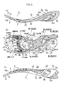
図1および図2に示すように、この陸上競技用の靴は、足を包むアッパー1と、該アッパー1の外側に設けられた靴底2とを備えている。靴底2は、非発泡体の樹脂を主材料として形成されている。図1(b)に示すように、靴底2の前足部2Fには、該靴底2の底面から突設された金属性のスパイク3や、スパイクを別途取り付けるための金属性のスパイク取付部材4などが設けられている。
As shown in FIGS. 1 and 2, this athletics shoe includes an upper 1 that wraps a foot and a
第1および第2樹脂10,20:
前記靴底2は、たとえば、熱可塑性樹脂で構成されており、ヤング率の小さい第1樹脂10と、該第1樹脂10よりもヤング率の大きい第2樹脂20とからなる2色の樹脂が一体に形成されてなる。したがって、第2樹脂20は第1樹脂10よりも足の屈曲により生じる曲げに対する剛性が大きく設定されている。
First and
The
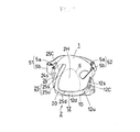
第1樹脂10:
図3(b)に示すように、第1樹脂10は、前足部2Fに設けた前領域11、踵部2Hに設けた後領域12、および前領域11と後領域12とを繋ぐ繋部13を備えている。
図3(a)〜(c)は、それぞれ、靴底2の内側面図、底面図および外側面図である。なお、図3では前記2色の樹脂を互いに区別するため、第2樹脂20に網点を施している。
前領域11はMP関節から爪先の間にわたって設けられている。前記MP関節とは、基節骨B(図3(b)の斜線で示した部分)と中足骨Cとによって構成される関節のことをいう。
First resin 10:
As shown in FIG. 3B, the
3A to 3C are an inner side view, a bottom view, and an outer side view of the
The
図3(c)に示すように、前記繋部13は、足の外側面に沿って略「へ」字状に形成されており、足のアーチの外側を側面から覆っている。前記後領域12は、後述する補強装置の一部を構成しており、踵部2Hの一部に設けられている。前領域11、後領域12および繋部13は、互いに滑らかに接続され、一体に形成されている。
As shown in FIG. 3 (c), the connecting
第2樹脂20:
図3(b)に示すように、第2樹脂20は、第1〜第5帯状部21〜25および連結バー30を備えている。第1〜4帯状部21〜24は、踏まず部2Bにおいて互いに一体に接続されており、シャンク26を形成している。第1〜第4帯状部21〜24は、シャンク26を中心に略「X」字状に滑らかに接続されている。このシャンク26は、運動時の足のネジレを抑制する。
Second resin 20:
As shown in FIG. 3B, the
連結バー30は、前足部2Fにおいて、第1帯状部21と第2帯状部22とを一体に連結している。第1帯状部21、第2帯状部22および連結バー30は、互いに滑らかに接続され、一体に形成されている。なお、第3〜第5帯状部23〜25は、後述する補強装置の一部を構成している。
The connecting
第1樹脂10の一部は第2樹脂20よりも下側に設けられている。連結バー30、第1および第2帯状部21,22は、第1樹脂10の前領域11の後部と重なり合っている(オーバーラップしている)。図1(b)に示すように、第1および第2帯状部21,22と連結バー30は、その周縁部が前足部2Fにおいて、第1樹脂10によって下側から覆われており、かつ、非周縁部(第1および第2帯状部21,22、ならびに、連結バー30のうち周縁部以外の部分)が第1樹脂10によって覆われていない。すなわち、底面側から見ると、第1および第2帯状部21,22と連結バー30上の部分において、第1樹脂10によって覆われていない部分が、略「H」字状に存在している。
A part of the
このように、前足部2Fにおいて、材料特性の違う樹脂を接着する際、第1樹脂10により第2樹脂20の周縁部を覆うことで、接着代(接着面積)をかせぐことができ、第1樹脂10と第2樹脂20との界面での割れを防止することができる。つまり、第1樹脂10が第2樹脂20から剥がれ難い。
また、第1樹脂10で、第2樹脂20の周縁部のみを覆うことにより、第2樹脂20の表面全体を覆う場合に比べ、靴底2の軽量化を図ることができる。
As described above, when the resin having different material characteristics is bonded to the
Further, by covering only the peripheral edge portion of the
第2帯状部22は、第1樹脂10の繋部13の前端部と若干オーバーラップしている。一方、踵部2Hにおいては、第3帯状部23および第5帯状部25の一部と第1樹脂10の後領域12とがオーバーラップしている。
The
つぎに、靴底2の詳細な構成について説明する。
前足部2F:
第1帯状部21;
図3(b)に示すように、第1帯状部21は、前足部2Fの後端(中足骨Cの足長方向の概ね中央)から第1指f1の第1基節骨B1近位骨頭の部位まで設けられている。第1帯状部21は、第2,3楔状骨D2,D3の部位から、第2中足骨C2および第1中足骨C1の部位を通って、第1基節骨B1の部位に至る領域に帯状に設けられている。
Next, a detailed configuration of the shoe sole 2 will be described.
As shown in FIG. 3 (b), the first band-
第1帯状部21は、第1指f1の第1基節骨B1遠位骨頭の近傍まで延びて配置されていると共に、第1末節骨A1まで延びていない。したがって、剛性の高い第2樹脂20からなる第1帯状部21が、指節間関節(末節骨Aと基節骨Bとの間の関節)を越えて第1末節骨A1まで延びていないから、第1末節骨A1と第1基節骨B1との間を曲げることが比較的容易となる。そのため、第1指f1において、第1末節骨A1と第1基節骨B1との間の指節(趾節)間関節における屈曲の自由度を高めて、自然な走り易さを確保することができる。
The first belt-
第2帯状部22;
第2帯状部22は、前足部2Fの後端(中足骨Cの足長方向の概ね中央)から第5指f5の第5基節骨B5遠位骨頭の部位まで設けられている。第2帯状部22は、第4中足骨C4の部位から、第5中足骨C5の部位を通って、第5基節骨B5の部位に至る領域に帯状に設けられている。
The second band-
第2帯状部22は、前記第1帯状部21と異なり、指節間関節を越えて第5末節骨A5遠位骨頭まで延びて配置されている。したがって、第5指f5については、剛性の高い第2樹脂20からなる第2帯状部22が、第5末節骨A5と第5基節骨B5との間の屈曲を抑制することにより、不要な足の屈曲を抑制することができる。
なお、第2帯状部22は、少なくとも第5末節骨A5近位骨頭以上まで延びて配置されていれば、当該効果を得ることができる。
Unlike the first belt-
In addition, if the 2nd strip | belt-shaped
第1および第2帯状部21,22;
第1および第2帯状部21,22は、それぞれ、MP関節から基節骨B1,B5遠位骨頭に至る領域において、足の屈曲により生じる曲げに対する剛性が、当該遠位骨頭に近づくに従い、概ね徐々に小さくなるように形成されている。すなわち、前足部2Fの爪先に近づくに従い、屈曲し易くなっていることで、爪先に近づく程、屈曲の自由度が大きくなるように設定されている。
First and
The first and second belt-
すなわち、図3(a)〜(c)に示すように、MP関節から基節骨B1,B5遠位骨頭に近づくに従い、第1および第2帯状部21,22の幅および厚さが小さくなるように設定されている。たとえば、図3(b)に示すように、第1および第2帯状部21,22は、MP関節から基節骨B1,B5遠位骨頭に近づくに従い幅が狭くなっていると共に、図3(a),(c)に示すように、厚さが徐々に小さくなるように設定されている。
したがって、前足部2Fに行くに従い、第1および第2帯状部21,22の剛性が徐々に小さくなる。
That is, as shown in FIGS. 3A to 3C, the widths and thicknesses of the first and second belt-
Therefore, the rigidity of the first and second belt-
図3(a)〜(c)に示すように、第1樹脂10の前領域11には、底面側に突出した突出部10a,10bが形成されている。突出部10a,10bは、第1帯状部21および第2帯状部22の前端部を覆うと共に、当該前端部に滑らかに連なるように形成されている。図1(b)に示すように、突出部10a,10bは前方に行くに従い、徐々に幅が狭くなり、かつ、図1(a),(b)に示すように、厚さが徐々に小さくなっている。
したがって、前足部2Fに行くに従い第1および第2帯状部21,22の剛性が徐々に小さくなると共に、突出部10a,10bにより、当該部分の第1樹脂10と第2樹脂20とが滑らかに繋がり、剛性が徐々に小さくなる。
As shown in FIGS. 3A to 3C, the
Accordingly, the rigidity of the first and second belt-
このように、前足部2Fの爪先に近づくに従い、屈曲し易くなっていることで、爪先に近づく程屈曲の自由度が大きくなる。
Thus, as it approaches the toe of the
連結バー30;
図3(b)に示すように、前記連結バー30は、第2指f2、第3指f3および第4指f4の中足骨C2,C3,C4の遠位骨頭に沿って配置されている。
したがって、ヤング率の大きい第2樹脂20で形成された連結バー30が、MP関節よりも後方に設けられているので、該MP関節よりも後方における足の屈曲を抑制することができる。また、第2〜第4指f2〜f4のMP関節の前方には、第2樹脂20は配置されておらず、かつ、本質的に第2樹脂20以上の剛性を有する樹脂は配置されていないので、第2〜第4指f2〜f4のMP関節およびその前方における曲げを許容することができるから、前足がMP関節において屈曲するのを抑制しつつ、前足の屈曲がMP関節および爪先部の両方の広いエリアで生じるようにすることが可能である。
また、連結バー30により、第1および第2帯状部21,22のネジレを抑制することができる。
Connecting
As shown in FIG. 3B, the connecting
Therefore, since the connecting
Further, the connecting
一方、連結バー30と、第1および第2帯状部21,22とは、それぞれ、第1指f1および第5指f5のMP関節を概ね中心として連なって形成されている。すなわち、第1および第2帯状部21,22と連結バー30との交差位置は、それぞれ、概ね、第1指f1および第5指f5のMP関節の部位である。
On the other hand, the connecting
したがって、第1指f1と第5指f5については、MP関節部分の剛性が最も大きいので、第1指f1および第5指f5についてはMP関節の屈曲を抑制し、一方、第2〜第4指f2〜f4についてはMP関節における屈曲が比較的容易となる。これにより、蹴り出し方向の内外へのブレを抑制して、前方への推進力を高めることができる。 Therefore, the MP joint portion has the highest rigidity for the first finger f1 and the fifth finger f5, and thus the bending of the MP joint is suppressed for the first finger f1 and the fifth finger f5, while the second to fourth Regarding the fingers f2 to f4, bending at the MP joint is relatively easy. Thereby, the blurring to the inside and outside of a kick-out direction can be suppressed, and the propulsive force to the front can be improved.
なお、第1および第2帯状部21,22、ならびに、連結バー30により、足の踏まず部からMP関節に至る領域において、第2樹脂20が略三角形状に形成されており、両帯状部21,22および連結バー30に囲まれる部分に貫通孔が形成されている。
In addition, the
繋部13:
図1(c)に示すように、第1樹脂10の繋部13は、前述したとおり略「へ」字状に形成されており、当該「へ」字状の部分がアッパー1の外側から足の踏まず部の外側面にフィットする形状に形成されている。なお、繋部13と第2樹脂20のシャンク26とは互いに離間して配置されており、その間には貫通孔が形成されている。
Connection part 13:
As shown in FIG. 1 (c), the connecting
踵部2Hの補強装置:
図3(b)に示す第1樹脂10の後領域12および第3〜第5帯状部23〜25は、アッパー1と一体となって足に沿う補強装置を構成している。
Reinforcing device for
The
第4帯状部24;
第4帯状部24は、踵骨Gの底面から内側面にかけて覆うように設けられている。図3(a)に示すように、第4帯状部24は、踵の内側面の一部を覆う内側面部24sと、踵の底面の一部を覆う底面部24d(図3(b))と、該底面部24dから内側面部24sへ巻き上がる内巻上部24uとが一体に成形されている。
A
The 4th strip | belt-shaped
第5帯状部25;
図3(b)に示すように、第5帯状部25は第4帯状部24の後方に設けられており、踵骨Gの底面から側面にかけて設けられている。図3(a)に示すように、第5帯状部25は第4帯状部24と同様に、それぞれ、踵の一部を覆う内側面部25s、底面部25d(図3(b))および内巻上部25uが一体に成形されてなる。
As shown in FIG. 3 (b), the fifth belt-
第4帯状部24および第5帯状部25により、内巻上部24u,25uおよび内側面部24s,25sは前後に2条に分けられて配置されている。第4帯状部24と第5帯状部25とは、その内側面部24s,25sの上部において接合されている。
Due to the fourth belt-
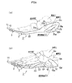
図4は靴底2に荷重が加わった状態の側面図であり、図4(a)は右足部分の内側面側、図4(b)は左足部分の外側面側を示している。
図4(a)に示すように、荷重が加わった状態では、第4および第5帯状部24,25の内側面部24s,25sは、踵骨の上端部(踵骨隆起G1の上端部Gu)まで覆っていると共に、距骨Jを全く覆っていない。更に、第4帯状部24の内側面部24sは舟状骨Eの下端の一部を覆っている。
FIG. 4 is a side view showing a state in which a load is applied to the
As shown in FIG. 4A, in the state where a load is applied, the inner
第3帯状部23;
図3(b)に示すように、第3帯状部23は踵骨Gの底面の内側から立方骨Fの底面にかけて覆うように設けられている。第3帯状部23は、踵の底面の一部を覆う底面部23dを備えている。前記第5帯状部25の底面部25dは、第3帯状部23の底面部23dに接続されている。したがって、第3〜第5帯状部23,24,25によって、貫通孔20hが形成されている。このように、貫通孔20hを形成することにより靴の軽量化を図ることができる。
As shown in FIG. 3B, the third belt-
前述のように、第1〜第4帯状部21〜24は、踏まず部2Bにおいて互いに接続され、一体に成形されている。したがって、補強部材の一部を構成する第3および第4帯状部23,24は、前記第1および第2帯状部21,22と共に、踏まず部2Bの屈曲を抑制するプレート状のシャンク26を形成している。すなわち、踵部2Hの補強装置はシャンク26と一体に形成されている。かかるシャンク26によって、足のネジレを抑制することができる。
As described above, the first to fourth belt-
図2の背面図に示すように、第5帯状部25における内側面部25sは、踵部2Hの背面において大きく切欠されていると共に、二点鎖線で示すように、その横断面が足の湾曲に沿うように湾曲している。第4帯状部24の横断面においても、第5帯状部25と同様に横断面が足の湾曲に沿うように湾曲している。
As shown in the rear view of FIG. 2, the inner
保形部材6;
図2に示すように、踵の背面部分には第1樹脂10および第2樹脂20は配置されていない。当該踵の背面部分のアッパー1には、図2の破線で示すように、たとえば、厚紙などで形成された保形部材(芯材)6が介挿され、固定されている。
前記保形部材6の内側面側は、アッパー1を介して第5帯状部25の内側面部25sに固定されている。また、保形部材6の底面側は、アッパー1を介して第5帯状部25の底面部25dおよび後領域12の底面部12dに固定されている。
なお、本実施例においては、保形のために保形部材6を使用したが、必ずしもかかる保形部材を使用せずともよく、使用しない場合はよりフィット性を高めることができる。
Shape retaining
As shown in FIG. 2, the
The inner surface side of the
In this embodiment, the shape-retaining
第1締付部材51;
アッパー1には、第4および第5帯状部24,25を足の甲FUの中央に向って引き上げて固定するための第1締付部材51が設けられている。第1締付部材51は、第4帯状部24の内側面部24sの前部分に固定された環状部5aと、該環状部5a内に挿通されたベルト状の固定部5bからなる。固定部5bは、足首の前方の足の甲FU部分に対応する位置に、アッパーの外側面部分から延びるように設けられている。固定部5bは、該甲FU部分から前記環状部5aに向って延びている。固定部5bは、環状部5a内に挿通され、折り返し部分を面ファスナを用いて固定することが可能である。
First fastening
The upper 1 is provided with a
着用時には、固定部5bを環状部5aに通し、足の甲FU部分のアッパー1に向って、固定部5bを引き上げ、面ファスナにより固定する。
したがって、前記第1締付部材51を締め付けて固定することにより、踵の底面、後端面および内側面が補強部材に固定される。踵の内側が第4および第5帯状部24,25により強化されているので、着地直後の踵部2Hの外反(踵骨回内)を抑制することができる。
At the time of wearing, the fixing
Therefore, by tightening and fixing the first tightening
また、第1締付部材51による締付により、第4帯状部24および第5帯状部25による2条の内側面部24s,25sが、それぞれ別個に変形するようにしてもよい。この場合、足の個人差のバラツキに容易に対応することができ、フィット性が向上する。
Further, by tightening by the first tightening
第1樹脂10の後領域12;
図1(b),(c)に示すように、第1樹脂10の後領域12は、踵部2Hの外側の側面および底面のそれぞれ一部を覆う帯状の外側面部12sおよび底面部12dと、底面部12dから外側面部12sへ巻き上がる外巻上部12uとが一体に形成されている。後領域12は、第3帯状部23の後部と、第5帯状部25の底面部25dにオーバーラップして設けられている。
A
As shown in FIGS. 1B and 1C, the
図4(b)に示すように、靴に荷重が加わった状態では、後領域12の外側面部12sは、踵骨Gの後端の下端部(踵骨隆起G1の後端の下端部)Gdから距骨Jに向って、踵骨Gの後端および下端の概ね1/2を覆っていると共に、踵骨隆起G1の前端部Gfおよび上端部Guを覆っていない。かかる外側面部12sの配置は、運動時に足の動きを阻害しないようにしつつ、後述する第2締付部材による張力が足の外側面全体の変形に及びやすくするためのものである。
As shown in FIG. 4 (b), in a state where a load is applied to the shoe, the outer
図2の二点鎖線で示すように、第1樹脂10の後領域12の横断面が、足の湾曲に沿うように湾曲して形成されている。図1(c)に示すように、前記外側面部12sは、前方に向って斜め上方に延びている。
As shown by a two-dot chain line in FIG. 2, the cross section of the
第2締付部材52;
アッパー1には、第2締付部材52が設けられている。第2締付部材52は、前述の第1締付部材51と同様に環状部5aおよびベルト状の固定部5bを備えており、環状部5aは外側面部12sの延長線上のアッパー1に設けられている。固定部5bは、足首の前方の足の甲FU部分に対応する位置に、アッパーの内側面部分から延びるように設けられている。固定部5bを環状部5aに通し、足の甲FUに向って引き上げて固定することができる。このとき、前記外側面部12s、環状部5aおよび固定部5bは、概ね同一直線上に位置する。
The upper 1 is provided with a
ここで、踵部2Hの底面および外側面の一部を覆う後領域12は、前述のように、剛性が低く足に沿い易い第1樹脂10で形成されている。したがって、第2締付部材52を締め付けて固定することにより、後領域12を踵部2Hの底面および側面に容易にフィットさせることができる。
Here, as described above, the
一方、前記保形部材6は、第1樹脂10の外側面部12sが足の外側面に沿って変形した場合に、アッパー1が踵部2Hの後部に沿って変形し易いように、小さめに形成されている。すなわち、図2に示すように、保形部材6は、踵部2Hの後端部のみを覆うように形成されている。そのため、保形部材6はアッパーの側面の変形を阻害せず、第2締付部材52を締め付けることにより、外側面部12sが足の外側面に沿って変形し、足の外側面に外側面部12sおよびアッパー1をフィットさせることができる。
したがって、補強装置の一部を構成する第1樹脂10の後領域12が踵の底部および外側面にフィットし易くなると共に、踵のホールド性が向上する。
なお、本実施例においては、保形のために保形部材6を使用したが、必ずしもかかる保形部材を使用せずともよく、使用しない場合はよりフィット性を高めることができる。
On the other hand, the
Therefore, the
In this embodiment, the shape-retaining
なお、前述の実施例では、締付部材51,52として、環状部5aおよび面ファスナを備えた固定部5bを例示して説明したが、補強装置を足の甲FUの中央に向って引き上げることが可能な部材であればよく、たとえば、環状部5aおよび固定部5bを用いる他に、アッパー1に紐を通して締め付けるようにしてもよい。
In the above-described embodiment, the fixing
また、第1樹脂10および第2樹脂20は、非発泡性の樹脂であればよく、熱可塑性や熱硬化性樹脂の他に、たとえば、FRP(fiber reinforced plastic)などの繊維強化性プラスチックなどを用いることができる。
Further, the
また、第2樹脂20の踵部の内側部分は、必ずしも2条に形成する必要はなく、3以上の複数条に形成することも可能であるし、あるいは、貫通孔20hを形成せずに第2樹脂20の踵部の内側部分を1本の帯状部としてもよい。
Further, the inner portion of the collar portion of the
また、第1樹脂10の後領域12については、必ずしも実施例に示す全ての部分を設ける必要はなく、例えば、外側面部12sを全く設けないようにしてもよい。更に、第1樹脂10の前領域11と後領域12とは必ずしも繋部13によって連結されている必要はなく、繋部13を設けずに前領域11と後領域12とを分断して形成してもよい。
Moreover, about the rear area |
本発明は、陸上競技や、フットボール、ラグビーなどの競技用の靴に利用することができる。 The present invention can be used for shoes for competitions such as athletics, football, and rugby.
2:靴底
3:スパイク
10:第1樹脂
20:第2樹脂
21:第1帯状部
22:第2帯状部
2F:前足部
30:連結バー
A:末節骨
B:基節骨
C:中足骨
f1:第1指
f2:第2指
f3:第3指
f4:第4指
f5:第5指
2: shoe sole 3: spike 10: first resin 20: second resin 21: first belt-like portion 22: second belt-
Claims (8)
前記樹脂がヤング率の小さい第1樹脂と、該第1樹脂よりもヤング率の大きい第2樹脂とで一体に形成され、
前記第1樹脂が前足部のMP関節から爪先の間にわたって設けられ、
前記第2樹脂が概ね第1指および第5指に沿って帯状に設けられた第1帯状部および第2帯状部を有し、
前記第1帯状部は、少なくとも前足部の後端から第1指の基節骨近位骨頭の部位まで設けられ、
前記第2帯状部は、少なくとも前足部の後端から第5指の基節骨近位骨頭の部位まで設けられているスパイクを備えた靴底。 In the shoe sole with spikes that protrude from the bottom of the shoe sole that is mainly made of non-foamed resin,
The resin is integrally formed of a first resin having a small Young's modulus and a second resin having a Young's modulus larger than the first resin,
The first resin is provided from the MP joint of the forefoot to the toes,
The second resin has first and second belt-like portions that are provided in a belt shape substantially along the first and fifth fingers,
The first band-shaped portion is provided at least from the rear end of the forefoot portion to the proximal phalanx of the first finger.
The second band-shaped portion is a shoe sole provided with a spike provided at least from the rear end of the forefoot portion to the proximal proximal phalanx of the fifth finger.
前記第1および第2帯状部は、その周縁部が前足部において前記第1樹脂によって覆われ、かつ、非周縁部が第1樹脂によって覆われていないスパイクを備えた靴底。 In any one of Claims 1-7,
The first and second belt-like portions are shoe soles having spikes whose peripheral portions are covered with the first resin at the front foot portions and non-peripheral portions are not covered with the first resin.
Priority Applications (1)
| Application Number | Priority Date | Filing Date | Title |
|---|---|---|---|
| JP2004112908A JP4020879B2 (en) | 2004-04-07 | 2004-04-07 | Shoe sole with spikes |
Applications Claiming Priority (1)
| Application Number | Priority Date | Filing Date | Title |
|---|---|---|---|
| JP2004112908A JP4020879B2 (en) | 2004-04-07 | 2004-04-07 | Shoe sole with spikes |
Publications (2)
| Publication Number | Publication Date |
|---|---|
| JP2005296093A true JP2005296093A (en) | 2005-10-27 |
| JP4020879B2 JP4020879B2 (en) | 2007-12-12 |
Family
ID=35328372
Family Applications (1)
| Application Number | Title | Priority Date | Filing Date |
|---|---|---|---|
| JP2004112908A Expired - Fee Related JP4020879B2 (en) | 2004-04-07 | 2004-04-07 | Shoe sole with spikes |
Country Status (1)
| Country | Link |
|---|---|
| JP (1) | JP4020879B2 (en) |
Families Citing this family (1)
| Publication number | Priority date | Publication date | Assignee | Title |
|---|---|---|---|---|
| JP6162784B2 (en) | 2015-12-24 | 2017-07-12 | 美津濃株式会社 | Outsole structure for shoes and creat shoes using the same |
-
2004
- 2004-04-07 JP JP2004112908A patent/JP4020879B2/en not_active Expired - Fee Related
Also Published As
| Publication number | Publication date |
|---|---|
| JP4020879B2 (en) | 2007-12-12 |
Similar Documents
| Publication | Publication Date | Title |
|---|---|---|
| JP4684986B2 (en) | Upper structure of shoes | |
| JP4327898B2 (en) | Athletic shoes with improved upper fit | |
| CN113453574B (en) | Article of footwear with wear protection | |
| JP5591421B1 (en) | Athletic shoes | |
| JP4076704B2 (en) | Sole structure of sports shoes | |
| JP3973053B2 (en) | Shoes with a deformable sole | |
| JP5103639B2 (en) | Shoe upper forefoot structure | |
| JPS6124001B2 (en) | ||
| JP3884688B2 (en) | Sole structure of Creet shoes | |
| JP2005152490A (en) | Shoes that fit your feet with a belt | |
| JP6162784B2 (en) | Outsole structure for shoes and creat shoes using the same | |
| WO2010038267A1 (en) | Athletic shoe with heel counter for maintaining shape of heel section | |
| WO2004093587A1 (en) | Sports shoes having upper part with improved fitting property | |
| WO2015155882A1 (en) | Shoe upper | |
| WO2007138947A1 (en) | Sole of spike shoe | |
| EP4312650B1 (en) | Lace-receiving structure for articles of footwear | |
| JP4020880B2 (en) | shoes | |
| JP4033647B2 (en) | Insole | |
| JP6581941B2 (en) | Shoe upper and shoes using the same | |
| JP4020879B2 (en) | Shoe sole with spikes | |
| JP3616285B2 (en) | Fastening structure for athletic shoes | |
| JP4920647B2 (en) | Upper structure of shoes | |
| JP7202870B2 (en) | shoes suitable for running | |
| JP6668194B2 (en) | footwear | |
| JP3887529B2 (en) | Sports shoe toe cover |
Legal Events
| Date | Code | Title | Description |
|---|---|---|---|
| A131 | Notification of reasons for refusal |
Free format text: JAPANESE INTERMEDIATE CODE: A131 Effective date: 20070403 |
|
| A521 | Request for written amendment filed |
Free format text: JAPANESE INTERMEDIATE CODE: A523 Effective date: 20070528 |
|
| TRDD | Decision of grant or rejection written | ||
| A01 | Written decision to grant a patent or to grant a registration (utility model) |
Free format text: JAPANESE INTERMEDIATE CODE: A01 Effective date: 20070918 |
|
| A61 | First payment of annual fees (during grant procedure) |
Free format text: JAPANESE INTERMEDIATE CODE: A61 Effective date: 20070925 |
|
| FPAY | Renewal fee payment (event date is renewal date of database) |
Free format text: PAYMENT UNTIL: 20101005 Year of fee payment: 3 |
|
| R150 | Certificate of patent or registration of utility model |
Free format text: JAPANESE INTERMEDIATE CODE: R150 Ref document number: 4020879 Country of ref document: JP Free format text: JAPANESE INTERMEDIATE CODE: R150 |
|
| FPAY | Renewal fee payment (event date is renewal date of database) |
Free format text: PAYMENT UNTIL: 20101005 Year of fee payment: 3 |
|
| FPAY | Renewal fee payment (event date is renewal date of database) |
Free format text: PAYMENT UNTIL: 20111005 Year of fee payment: 4 |
|
| FPAY | Renewal fee payment (event date is renewal date of database) |
Free format text: PAYMENT UNTIL: 20121005 Year of fee payment: 5 |
|
| FPAY | Renewal fee payment (event date is renewal date of database) |
Free format text: PAYMENT UNTIL: 20121005 Year of fee payment: 5 |
|
| FPAY | Renewal fee payment (event date is renewal date of database) |
Free format text: PAYMENT UNTIL: 20131005 Year of fee payment: 6 |
|
| FPAY | Renewal fee payment (event date is renewal date of database) |
Free format text: PAYMENT UNTIL: 20131005 Year of fee payment: 6 |
|
| FPAY | Renewal fee payment (event date is renewal date of database) |
Free format text: PAYMENT UNTIL: 20141005 Year of fee payment: 7 |
|
| LAPS | Cancellation because of no payment of annual fees |