JP2005296028A - Manufacturing method of foam molding article integrated with facing body - Google Patents
Manufacturing method of foam molding article integrated with facing body Download PDFInfo
- Publication number
- JP2005296028A JP2005296028A JP2004111844A JP2004111844A JP2005296028A JP 2005296028 A JP2005296028 A JP 2005296028A JP 2004111844 A JP2004111844 A JP 2004111844A JP 2004111844 A JP2004111844 A JP 2004111844A JP 2005296028 A JP2005296028 A JP 2005296028A
- Authority
- JP
- Japan
- Prior art keywords
- opening
- skin
- epidermis
- foaming
- facing body
- Prior art date
- Legal status (The legal status is an assumption and is not a legal conclusion. Google has not performed a legal analysis and makes no representation as to the accuracy of the status listed.)
- Pending
Links
- 238000004519 manufacturing process Methods 0.000 title claims abstract description 33
- 238000010097 foam moulding Methods 0.000 title abstract description 5
- 239000011347 resin Substances 0.000 claims abstract description 51
- 229920005989 resin Polymers 0.000 claims abstract description 51
- 238000005187 foaming Methods 0.000 claims abstract description 21
- 238000000465 moulding Methods 0.000 claims abstract description 18
- 210000003491 skin Anatomy 0.000 claims description 60
- 210000002615 epidermis Anatomy 0.000 claims description 48
- 239000006260 foam Substances 0.000 claims description 10
- 238000005452 bending Methods 0.000 claims description 4
- 239000000463 material Substances 0.000 abstract description 3
- 238000004904 shortening Methods 0.000 abstract description 3
- 238000002347 injection Methods 0.000 description 20
- 239000007924 injection Substances 0.000 description 20
- 238000000034 method Methods 0.000 description 11
- 230000000694 effects Effects 0.000 description 10
- 238000009958 sewing Methods 0.000 description 5
- 238000003780 insertion Methods 0.000 description 3
- 230000037431 insertion Effects 0.000 description 3
- 230000002093 peripheral effect Effects 0.000 description 3
- 230000002195 synergetic effect Effects 0.000 description 3
- 230000008602 contraction Effects 0.000 description 2
- 230000002265 prevention Effects 0.000 description 2
- 238000013459 approach Methods 0.000 description 1
- 238000011109 contamination Methods 0.000 description 1
- 238000000275 quality assurance Methods 0.000 description 1
Images


Landscapes
- Mattresses And Other Support Structures For Chairs And Beds (AREA)
Abstract
Description
本願発明は、例えば、車両用ヘッドレストの如く袋状に縫製された表皮体内に直接発泡樹脂を注入し且つこれを発泡させて該表皮体内にコアを形成してなる一体発泡成形品の製造方法に関するものである。 The present invention relates to a method for manufacturing an integrally foamed molded article, for example, in which a foamed resin is directly injected into a skin body sewn in a bag shape like a vehicle headrest and foamed to form a core in the skin body. Is.
一般に、表皮体一体発泡成形品の製造に際しては、発泡樹脂注入用の開口部を有するように縫製された表皮体内に上記開口部から注入ノズルを挿入し、該注入ノズルを通して上記表皮体内に発泡樹脂を注入してこれを発泡させ、該表皮体内にコアを形成する手法をとる(例えば、特許文献1,2参照)。 In general, in the production of a foam integrated with an epidermis, an injection nozzle is inserted into the epidermis sewn so as to have an opening for injecting a foam resin, and the foam resin is inserted into the epidermis through the injection nozzle. Is injected and foamed to form a core in the epidermis (see, for example, Patent Documents 1 and 2).
この場合、表皮体内に注入された発泡樹脂が該表皮体内で発泡する際に上記開口部から樹脂が外部へ漏れ出る虞があり、樹脂が漏れ出るとこれが表皮に付着しその美観性を損ねるとともに、事後的に付着物の除去作業が必要となって、コストアップになるという問題がある。 In this case, when the foamed resin injected into the epidermis foams in the epidermis, the resin may leak out from the opening, and when the resin leaks, it adheres to the epidermis and impairs its aesthetics. However, there is a problem that the removal work of the adhering matter is necessary after the fact, and the cost is increased.
このような事情から、樹脂発泡時の樹脂漏洩を防止すべく従来から種々の手段が提案されている。例えば、特許文献1には、表皮体の開口部に板状の冶具をセットし、該冶具によって上記開口部をその長さ方向に引っ張ってこれを閉塞させ、該開口部からの発泡圧による樹脂の漏出を防ぐようにしたものが示されている。 Under such circumstances, various means have been conventionally proposed to prevent resin leakage during foaming of the resin. For example, in Patent Document 1, a plate-shaped jig is set in an opening portion of an epidermis body, the opening portion is pulled in the length direction by the jig, and this is closed, and a resin is generated by foaming pressure from the opening portion. It is shown to prevent leakage.
また、特許文献2には、表皮体の開口部の両端部にそれぞれ摺動杆をセットし、該各摺動杆を外側へ引っ張ることで該開口部を閉じて樹脂の発泡圧による漏出を防ぐようにしたものが示されている。
In
ところが、特許文献1に示される手法によれば、板状の冶具を開口部に取り付けて該開口部をその長さ方向に引っ張ってこれを閉塞させるようにしているが、通常、上記表皮体は縫製により製作されるものでその開口部の開口長さ寸法には比較的大きなバラツキがあるのが通例であるところ、上記冶具の板長さは一定に固定されていることから、上記開口部の寸法のバラツキ幅によっては、上記冶具では上記開口部を確実に引っ張ってこれを閉塞させることが出来ない場合もあり、上記開口部からの樹脂の漏出防止作用の安定性あるいは信頼性という点において問題があった。 However, according to the method shown in Patent Document 1, a plate-shaped jig is attached to the opening and the opening is pulled in the length direction to close it. Usually, the size of the opening of the opening is relatively large, and the length of the opening of the jig is fixed at a constant value. Depending on the variation width of the dimensions, the jig may not be able to reliably close the opening by pulling the opening, which is problematic in terms of the stability or reliability of the resin leakage prevention action from the opening. was there.
また、特許文献2に示される手法は、表皮体の開口部の両端部にそれぞれ摺動杆をセットし、該各摺動杆を外側へ引っ張ることで上記開口部を閉塞させるようにしているが、該各摺動杆はこれを外側へ引っ張る構成であることからして、該各摺動杆はこれが成形型側に取り付けられるのが構成上通例と考えられ、かかる構成であれば、先ず、表皮体を成形型にセットした後、該表皮体に上記各摺動杆をセットしなければならず、発泡樹脂の注入前のセット作業に手間が掛かることになる。
Moreover, although the method shown by
しかるに、実際の作業においては、成形品1個当たりのタクトタイムの決まっており、このタクトタイム内で表皮体のセットのみならず、上記各摺動杆のセット作業を完了する必要があることから、場合によっては該各摺動杆の適正なセットが担保されず、その結果、生産性及び品質の確保が困難になる等の問題が発生することが懸念される。さらに、上記各摺動杆が成形型側に設けられていることで、該各摺動杆の上記表皮体側からの取り外し作業は上記成形型の型開き後でないとできず、このことも生産性及び品質の確保を阻害する一因となる。 However, in actual work, the tact time per molded product is determined, and within this tact time, it is necessary to complete not only the setting of the epidermis but also the setting work of each of the above sliding rods. In some cases, an appropriate set of the sliding rods is not secured, and as a result, there is a concern that problems such as difficulty in securing productivity and quality may occur. Furthermore, since each sliding rod is provided on the mold side, the removal operation of each sliding rod from the skin body side can be performed only after the mold is opened. And contributes to the impediment to quality assurance.
そこで本願発明では、表皮体の開口部からの樹脂材の漏出防止を安定的に且つ高い信頼性をもって実現し、成形品の生産性及び品質の確保を可能とする表皮一体発泡成形品の製造方法を提案することを目的としてなされたものである。 Therefore, in the present invention, a method for producing a skin-integrated foam-molded product that realizes prevention of leakage of the resin material from the opening of the skin body stably and with high reliability, and can ensure the productivity and quality of the molded product. It was made for the purpose of proposing.
本願発明ではかかる課題を解決するための具体的手段として次のような構成を採用している。 In the present invention, the following configuration is adopted as a specific means for solving such a problem.
本願の第1の発明では、切溝状の開口部21を備えた袋状の表皮体2内に該開口部21から発泡樹脂を注入しこれを発泡させてコア3を成形する表皮体一体発泡成形品の製造方法において、上記表皮体2の上記開口部21に弾性復元作用をもつ拡張具5を装着し該拡張具5の弾性復元作用によって上記開口部21をその溝長方向へ拡張させ、その状態で上記表皮体2を成形型10にセットすることを特徴としている。
In the first invention of the present application, a skin-body-integrated foam for forming a
本願の第2の発明では、上記第1の発明に係る表皮一体発泡成形品の製造方法において、上記拡張具5を、弾性をもつワイヤーを略コ字状に屈曲させて構成し、且つその両端の作用部5b,5bを狭閉方向に弾性変形させた状態で該作用部5b,5b部分を上記開口部21内に装着することを特徴としている。
According to a second invention of the present application, in the method for manufacturing a skin-integrated foam-molded product according to the first invention, the
本願の第3の発明では、上記第1の発明に係る表皮一体発泡成形品の製造方法において、上記拡張具5を、両端を作用部5b,5bとしたコイルスプリングで構成し、且つ縮小方向に弾性変形させた状態で該作用部5b,5b部分を上記開口部21内に装着することを特徴としている。
According to a third invention of the present application, in the method for manufacturing a skin-integrated foam-molded product according to the first invention, the
本願の第4の発明では、上記第1、第2又は第3の発明に係る表皮体一体発泡成形品の製造方法において、上記拡張具5を、上記開口部21における上記表皮体2の内方への折返部22に配置することを特徴としている。
According to a fourth invention of the present application, in the method for manufacturing an epidermis integrated foam molded product according to the first, second or third invention, the
本願の第5の発明では、上記第1、第2、第3又は第4の発明に係る表皮体一体発泡成形品の製造方法において、上記拡張具5を、上記表皮体2内での上記発泡樹脂の発泡後に除去することを特徴としている。
According to a fifth invention of the present application, in the method for producing an epidermis-integrated foamed molded product according to the first, second, third, or fourth invention, the
本願発明では次のような効果が得られる。 In the present invention, the following effects can be obtained.
(a)本願の第1の発明では、切溝状の開口部21を備えた袋状の表皮体2内に該開口部21から発泡樹脂を注入しこれを発泡させてコア3を成形する表皮体一体発泡成形品の製造方法において、上記表皮体2の上記開口部21に弾性復元作用をもつ拡張具5を装着し該拡張具5の弾性復元作用によって上記開口部21をその溝長方向へ拡張させ、その状態で上記表皮体2を成形型10にセットするようにしている。
(A) In the first invention of the present application, the
従って、この発明の表皮一体発泡成形品の製造方法によれば、上記拡張具5の弾性復元作用によって上記開口部21をその溝長方向へ拡張させることで上記開口部21をその溝幅方向に引き寄せてこれを閉塞させる構成であることから、この閉塞された上記開口部21の一部を押し開いて上記表皮体2内に発泡樹脂を注入しこれを発泡させる場合、該開口部21から発泡樹脂がその発泡圧によって漏出するのが可及的に防止され、漏出樹脂が上記表皮体2の表面に付着することによる成形品の汚れがなく、また付着樹脂の除去作業も不要であり、その結果、高品質の成形品を安価に提供できる。
Therefore, according to the manufacturing method of the skin-integrated foam molded product of the present invention, the
また、上記拡張具5は、上記表皮体2を上記成形型10にセットする前に該表皮体2に取り付け、該拡張具5を取り付けたまま上記表皮体2を上記成形型10にセットすることができる構成であって、該拡張具5の上記表皮体2への取り付け作業は、これを上記表皮体2の上記成形型10へのセット作業とは別個に行なうことができ、従って、成形品1個当たりのタクトタイムの決まっていても、このタクトタイム内で上記表皮体2を上記成形型10に確実にセットすることができ、その結果、成形品の高い生産性が実現されると共に、その品質の向上を図ることができる。
Further, the
(b)本願の第2の発明では、上記(a)に記載の効果に加えて次のような特有の効果が得られる。即ち、この発明では、上記拡張具5を、弾性をもつワイヤーを略コ字状に屈曲させて構成し、且つその両端の作用部5b,5bを狭閉方向に弾性変形させた状態で該作用部5b,5b部分を上記開口部21内に装着するようにしているので、上記拡張具5がコンパクトでその取り扱いが容易であり該拡張具5のセット作業の効率化が図れると共に、該拡張具5がワイヤーでなる簡易且つ安価な構成であり、これらの相乗効果として、成形品の製造コストの低廉化を図ることができる。
(B) In the second invention of the present application, in addition to the effect described in the above (a), the following specific effect is obtained. That is, in the present invention, the
(c)本願の第3の発明では、上記(a)又は(b)に記載の効果に加えて次のような特有の効果が得られる。即ち、この発明では、上記拡張具5を、両端を作用部5b,5bとしたコイルスプリングで構成し、且つ縮小方向に弾性変形させた状態で該作用部5b,5b部分を上記開口部21内に装着するようにしているので、上記拡張具5がコンパクトでその取り扱いが容易であり該拡張具5のセット作業の効率化が図れると共に、該拡張具5がコイルスプリングでなる簡易且つ安価な構成であり、これらの相乗効果として、成形品の製造コストの低廉化を図ることができる。
(C) In the third invention of the present application, in addition to the effects described in the above (a) or (b), the following specific effects can be obtained. In other words, in the present invention, the
(d)本願の第4の発明では、上記拡張具5を、上記開口部21における上記表皮体2の内方への折返部22に配置するようにしているので、該拡張具5による拡張力を上記開口部21部分に確実に作用させることができ、これによって上記(a),(b)又は(c)に記載の効果がより一層確実ならしめられる。
(D) In the fourth invention of the present application, the
(e)本願の第5の発明では、上記(a),(b),(c)又は(d)に記載の効果に加えて次のような特有の効果が得られる。即ち、この発明では、上記拡張具5を、上記表皮体2内での上記発泡樹脂の発泡後に、換言すれば、成形型10の型開き前に、除去するようにしているので、例えば上記拡張具5を上記成形型10の型開き後に行なう必要がある構成の場合に比して、タクトタイム内での作業完了が確実となり、延いてはタクトタイムの短縮による生産性の更なる向上も期待できる。
(E) In the fifth invention of the present application, in addition to the effects described in the above (a), (b), (c) or (d), the following specific effects can be obtained. That is, in the present invention, the
以下、本願発明を好適な実施形態に基づいて具体的に説明する。 Hereinafter, the present invention will be specifically described based on preferred embodiments.
図1には、本願発明の実施形態に係る製造方法を使用して製造された表皮一体発泡成形品としての車両用シートのヘッドレスト1を示している。このヘッドレスト1は、予め表皮材を用いて袋状に縫製された表皮体2にポール4をインサートし、この状態で上記表皮体2内に発泡樹脂を適量注入し、これを発泡させることで該表皮体2内に該表皮体2の縫製形状及び成形型のキャビテェ形状に対応した形状をもつコア3を形成してなるものである。
FIG. 1 shows a headrest 1 of a vehicle seat as a skin-integrated foam-molded product manufactured using a manufacturing method according to an embodiment of the present invention. The headrest 1 has a pole 4 inserted in a
この場合、上記表皮体2は、上記ヘッドレスト1の外周面を構成するように筒状に縫製されたセンター表皮25と該センター表皮25の左右両端に縫合連結されて該センター表皮25の両端開口を閉塞する左右一対のサイド表皮26で形成される。
In this case, the
また、上記ポール4の左右の脚部4a,4aが突出した上記ヘッドレスト1の下面には、上記センター表皮25の周方向両端縁25a,25aの幅方向中央部分を未縫合のまま内側へ折り返して折返部22,22が設けられるとともに、該各折返部22,22の間が開閉可能な開口部21とされており、該表皮体2内への発泡樹脂の注入は、上記開口部21を通して上記開口部21内に挿入される注入ノズルを用いて行なわれる。
Further, on the lower surface of the headrest 1 from which the left and right legs 4a, 4a of the pole 4 protrude, the center portions in the width direction of the
従って、製品としての上記ヘッドレスト1の美観性を確保してその商品価値を高めると共に、事後作業を無くしてその製造コストを低く抑えるためには、上記表皮体2内でのコア3の発泡成形時に発泡樹脂がその発泡圧によって上記開口部21から外部へ漏出することを防止することが必要となる。
Therefore, in order to secure the aesthetics of the headrest 1 as a product to increase its commercial value and to reduce the manufacturing cost by eliminating the subsequent work, at the time of foam molding of the
本願発明は係る観点からなされたものであって、その製造方法において新規な構成を採用している。以下、上記事項と重複する部分もあるが、この新規構成を含む具体的な製造方法を、図2以下を参照して説明する。 The present invention has been made from such a viewpoint, and adopts a novel configuration in the manufacturing method. Hereinafter, although there is a part which overlaps with the said matter, the specific manufacturing method including this novel structure is demonstrated with reference to FIG.
先ず、図3及び図4を参照して、上記表皮体2の縫製手順等を説明する。上記表皮体2は、上述のようにセンター表皮25と左右一対のサイド表皮26を縫合連結して得られるが、その場合、先ず、上記センター表皮25は、その両端縁25a,25aの幅方向中央寄り部分を外方へ延出させた凹凸形状に生地を裁断する。このセンター表皮25の両端縁25a,25aから延出する部分は、後述する折返部22をなるものである。
First, with reference to FIG.3 and FIG.4, the sewing procedure etc. of the said
そして、図3に示すように、上記センター表皮25をその裏面25cを表に出した裏返し状態で二つ折りに折り重ね合わせ、先ず縫合線L1で示すように上記両端縁25aから上記折返部22の縁部に対応する部位までを縫合すると共に、さらに、縫合線L2で示すように上記折返部22の外端から所定寸法だけ縫合する。従って、上記折返部22の端縁部分は、その幅方向両端部が僅かに縫合され、それらの内側に位置する部分は未縫合状態とされる。
Then, as shown in FIG. 3, the
次に、上記縫合によって筒状形態とされた上記センター表皮25の両側縁のそれぞれに、縫合線L3で示すように、上記サイド表皮26を縫合連結する。これで、上記表皮体2の縫製が完了する。
Next, the side epidermis 26 is stitched and connected to both side edges of the center epidermis 25 formed into a tubular shape by the suturing, as indicated by a suture line L3. This completes the sewing of the
しかる後、上記表皮体2を表裏反転させ、上記センター表皮25の表面25cを表に出した状態が図4に示す状態である。この状態では、上記折返部22部分は、これを表裏反転させずにそのまま残している。従って、上記表皮体2は、上記折返部22を除く他の部分ではその表面が表に出ているが、上記折返部22部分は裏返し状態のまま上記表皮体2内に折り込まれた状態となっている。そして、この折返部22のうち、未縫合のまま残された部分は、上記開口部21とされる。
After that, the state in which the
このように縫製された上記表皮体2を、図2に示すように、成形型10にセットしてその内部に発泡樹脂を注入する。この場合、上記表皮体2を上記成形型10にセットするのに先立って、先ず、上記表皮体2に上記ポール4をセットしてその脚部4a,4aをそれぞれ上記表皮体2に設けた通孔23を通して外方へ突出させる。
As shown in FIG. 2, the above-described
さらに、上記表皮体2の上記開口部21部分に、本願発明の要旨をなす次述の拡張具5をセットする。即ち、上記拡張具5は、上記開口部21をその溝長方向に拡張させて該開口部21を閉塞せしめるためのものであって、図2及び図5に示すように、弾性をもつ所定径のワイヤーを略コ字状に屈曲させ、その両端で直状に延びる左右一対の部分をそれぞれ作用部5bとし、該各作用部5b,5bの間に位置する部分を基部5aとすると共に、これら各作用部5b,5bと上記基部5aの連続部分はこれを環状に巻成して弾性復元性を高めた構成とすると共に、該各作用部5b,5bと上記基部5aとが略直交するように折曲させている。
Furthermore, the following
そして、このように構成された上記拡張具5を、図2及び図5に示すように、各作用部5b,5bを狭閉方向(図5の矢印C方向)に弾性変形させた状態で、上記表皮体2の開口部21内に挿入し、該各作用部5b,5bをそれぞれ上記折返部22の両端部に対応させる。この場合、上記作用部5bの上記開口部21内への挿入量は、該作用部5bの先端が上記縫合線L2に対応する部位に当たりそれ以上の進入が規制されることで自動的に適正挿入量に設定され、該作用部5bの上記開口部21内への過剰な挿入が阻止される。
And in the state which made the said
上記拡張具5の上記各作用部5b,5bを上記開口部21内へ挿入した後、該拡張具5に対する狭閉作用を解除する。すると、該拡張具5の上記各作用部5b,5bは、その弾性復元作用によって拡開方向(図5の矢印O方向)へ弾性変形し、その変形力が上記開口部21の溝長方向の両端間に作用することで該開口部21は溝長方向に拡張変形され、この拡張変形に伴って該開口部21は、その両壁(即ち、上記一対の折返部22,22)が相互に接近して弾性的に閉塞されることになる。
After the
このように、上記ポール4と上記拡張具5がそれぞれ取り付けられた上記表皮体2は、これらと一体に、上記成形型10にセットされる。
In this way, the
即ち、図2に示すように、上記成形型10(ここでは、下型と上型のうち、下型のみを示すと共に、この下型を「成形型10」として説明する)は、所定形状の成形室11を備えると共に、上型との衝合面12には、平底のノズル装着部13と該ノズル装着部13の左右両側に位置する丸底の楔状凹部でなるポール装着部14,14と該各ポール装着部14,14の外側に位置する左右一対に平底の拡張具装着部15、15を備えている。また、上記成形室11の前面には、上記ノズル装着部13に対応するように延設支持部18が設けられている。
That is, as shown in FIG. 2, the mold 10 (here, only the lower mold of the lower mold and the upper mold is shown and this lower mold is described as “
そして、上記成形型10の成形室11内へ上記表皮体2を、上記ポール4及び上記拡張具5を装着したままセットする。この場合、上記表皮体2側の上記ポール4の各脚部4a,4aは上記ポール装着部14,14に、また上記拡張具5の各作用部5b,5bは上記拡張具装着部15,15にそれぞれ対応している。また、上記拡張具5の基部5aは、上記ポール4の各脚部4a,4aの下側を迂回した状態で配置されている。
Then, the
このように上記表皮体2を上記成形型10にセットした後、上記開口部21の上側の側壁(即ち、一方の折返部22)を適宜引き上げて上記開口部21を適度に開き、この開いた部分から、その外周をシールペーパ17によって包んだ注入ノズル16を、該シールペーパ17とともに上記表皮体2内に挿入し、且つこれを上記延設支持部18に支持させる。
After setting the
以上で、上記成形型10への上記表皮体2のセット作業が完了する。この表皮体2のセット状態においては、上記表皮体2の上記開口部21を通して上記注入ノズル16が挿入されているものの、該開口部21は上記拡張具5の弾性復元力によって溝幅方向に拡張されていることから、該注入ノズル16に密着状態で閉塞された状態となっている。
Thus, the setting operation of the
従って、この状態で、上記注入ノズル16を通して上記表皮体2内に発泡樹脂を適量注入し、これを該表皮体2内で発泡させて上記コア3を形成する。この場合、上記注入ノズル16は、発泡樹脂の注入完了後に上記表皮体2側から引き抜いて取り外すが、その際、上記注入ノズル16は、上記シールペーパ17によってその外周面が拭われる状態となり、上記表皮体2内に注入された発泡樹脂の一部が上記注入ノズル16の外周面に付着していたとしても、これが上記開口部21の内面に付着してこれを汚損するようなことが確実に防止される。
Therefore, in this state, an appropriate amount of foamed resin is injected into the
また、上記表皮体2内に注入された発泡樹脂が発泡する場合、その発泡圧によって樹脂の一部が上記開口部21から外部へ漏出する虞があるが、この実施形態の方法によれば、上記開口部21が上記拡張具5の弾性復元作用によって可及的に閉塞状態とされているため、この樹脂の漏出が確実に防止される。従って、開口部21からの樹脂の漏出による開口部21部分の汚損がなく、また漏出樹脂を除去するための事後作業も必要としない。
Further, when the foamed resin injected into the
上記表皮体2内での発泡樹脂の発泡作用が終了した時点、又は終了間近となった時点で、上記拡張具5を上記表皮体2側から取り外す。この場合、上記拡張具5が上記成形型10側には何ら結合されていないので、該拡張具5はこれを上記成形型10の型開き等の作業とは何ら関係なく取り外すことができ、作業性の向上が図れる。
At the time when the foaming action of the foamed resin in the
上記表皮体2内での発泡成形作用が完了した後、上記成形型10を型開きしてその成形室11から上記表皮体2を取り出すことで、図1に示す如きヘッドレスト1が得られる。
After the foam molding operation in the
以上のような手順で行なわれるこの実施形態の製造方法によれば、以下のような特有の効果が得られる。 According to the manufacturing method of this embodiment performed in the above procedure, the following specific effects can be obtained.
即ち、上記拡張具5の弾性復元作用によって上記開口部21をその溝長方向へ拡張させることで上記開口部21をその溝幅方向に引き寄せてこれを閉塞させる構成であることから、この閉塞された上記開口部21の一部を押し開いて上記注入ノズル16をセットし、該注入ノズル16を通して上記表皮体2内に発泡樹脂を注入しこれを発泡させる場合、該開口部21から発泡樹脂がその発泡圧によって漏出するのが可及的に防止され、漏出樹脂が上記表皮体2の表面に付着することによる成形品の汚れがなく、また付着樹脂の除去作業も不要であり、その結果、高品質の成形品を安価に提供できる。
That is, since the
また、上記拡張具5は、上記表皮体2を上記成形型10にセットする前に該表皮体2に取り付け、該拡張具5を取り付けたまま上記表皮体2を上記成形型10にセットすることができる構成であって、該拡張具5の上記表皮体2への取り付け作業は、これを上記表皮体2の上記成形型10へのセット作業とは別個に行なうことができ、従って、成形品1個当たりのタクトタイムの決まっていても、このタクトタイム内で上記表皮体2を上記成形型10に確実にセットすることができ、その結果、成形品の高い生産性が実現されると共に、その品質の向上を図ることができる。
Further, the
さらに、上記拡張具5を、弾性をもつワイヤーを略コ字状に屈曲させて構成し、且つその両端の作用部5b,5bを狭閉方向に弾性変形させた状態で該作用部5b,5b部分を上記開口部21内に装着するようにしているので、上記拡張具5がコンパクトでその取り扱いが容易であり該拡張具5のセット作業の効率化が図れると共に、該拡張具5がワイヤーでなる簡易且つ安価な構成であり、これらの相乗効果として、成形品の製造コストの低廉化を図ることができる。
Furthermore, the
また、上記拡張具5を、上記開口部21における上記表皮体2の内方への折返部22に配置するようにしているので、該拡張具5による拡張力を上記開口部21部分に確実に作用させることができ、該拡張具5を備えたことによる樹脂漏出防止作用が寄り一層確実ならしめられる。
In addition, since the
さらに、上記拡張具5を、上記表皮体2内での上記発泡樹脂の発泡後に、換言すれば、成形型10の型開き前に、除去するようにしているので、例えば上記拡張具5を上記成形型10の型開き後に行なう必要がある構成の場合に比して、タクトタイム内での作業完了が確実となり、延いてはタクトタイムの短縮による生産性の更なる向上も期待できる。
Furthermore, the
ここで、上記拡張具5の他の構造例をいくつか説明する。
Here, some other structural examples of the
図6は、上記実施形態における上記拡張具5の変形例として位置付けられるものであって、上記実施形態の拡張具5と基本構造を同じにし、これと異なる点は、拡張具5の左右一対の作用部5bを直状とせずに、これをその中段で段状に折曲形成した点である。このように構成することで、上記段部分を上記開口部21の肩部に対応させることで、該作用部5bの挿入量の適正設定が可能になり、上記実施形態の場合のように縫合部分(図4の縫合線L2の部分)で拡張具5の挿入量規制を行なわなくても良く、それだけ縫製作業の簡略化が図れることである。これ以外の基本的効果は、上記実施形態の場合と同様である。
FIG. 6 is positioned as a modified example of the
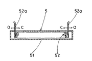
図7は、上記実施形態のもの、及び図6に示したものとは異なり、上記拡張具5をコイルバネ52で構成したものである。即ち、コイルバネ52をケース51内に収納してその伸縮方向を規定すると共に、該コイルバネ52の両端をそれぞれ上記ケース51からそれぞれ外側へ延出させてこれを作用部52a,52aとしたものである。
FIG. 7 is different from the above embodiment and the one shown in FIG. 6 in that the
尚、上記実施形態においては、上記表皮体2内への発泡樹脂の注入を上記注入ノズル16を用いて行なうようにしているが、本願発明の製造方法は係る注入手法を備えるものに限定されるものではなく、例えば、該注入ノズル16を用いずに、上記開口部21を適宜開いてここから上記表皮体2内に発泡樹脂を直接注入する構成のものにも適用できることは言うまでもない。このような直接注入手法は、上記開口部21が上記拡張具5によって弾性的に閉塞されており、これを一旦開いて発泡樹脂の注入を行なった後、この開口力を解除することで上記開口部21が再度上記拡張具5の弾性復元力で閉塞されるというこの発明に特有の構成によって可能となるものである。
In the above embodiment, the foamed resin is injected into the
1 ・・ヘッドレスト
2 ・・表皮体
3 ・・コア
4 ・・ポール
5 ・・拡張具
10 ・・成形型
11 ・・成形室
12 ・・衝合面
13 ・・ノズル装着部
14 ・・ポール装着部
15 ・・拡張具装着部
16 ・・注入ノズル
17 ・・シールペーパ
21 ・・開口部
22 ・・折返部
23 ・・通孔
25 ・・センター表皮体
26 ・・サイド表皮体
51 ・・ケース
52 ・・コイルバネ
1 ··
Claims (5)
上記表皮体(2)の上記開口部(21)に弾性復元作用をもつ拡張具(5)を装着し該拡張具(5)の弾性復元作用によって上記開口部(21)をその溝長方向へ拡張させ、その状態で上記表皮体(2)を成形型(10)にセットすることを特徴とする表皮体一体発泡成形品の製造方法。 A skin-integrated foam for injecting foamed resin from the opening (21) into the bag-shaped skin (2) having a kerf-shaped opening (21) to form the core (3). A method of manufacturing a molded article,
An expander (5) having an elastic restoring action is attached to the opening (21) of the epidermis (2), and the opening (21) is moved in the groove length direction by the elastic restoring action of the expander (5). A method for producing a skin-body-integrated foam-molded product, wherein the skin body (2) is expanded and set in the molding die (10) in that state.
上記拡張具(5)が、弾性をもつワイヤーを略コ字状に屈曲させて構成され且つその両端の作用部(5b),(5b)を狭閉方向に弾性変形させた状態で該作用部(5b),(5b)部分を上記開口部(21)内に装着することを特徴とする表皮体一体発泡成形品の製造方法。 In claim 1,
The extension device (5) is formed by bending an elastic wire in a substantially U-shape and the action portions (5b) and (5b) at both ends thereof are elastically deformed in a narrow closing direction. (5b) A method for producing an epidermis-integrated foam molded product, wherein the portions (5b) and (5b) are mounted in the opening (21).
上記拡張具(5)が、両端を作用部(5b),(5b)としたコイルスプリングで構成され、且つ縮小方向に弾性変形させた状態で該作用部(5b),(5b)部分を上記開口部(21)内に装着することを特徴とする表皮体一体発泡成形品の製造方法。 In claim 1,
The expander (5) is composed of a coil spring having both ends as acting portions (5b) and (5b), and the acting portions (5b) and (5b) are in the state of being elastically deformed in the shrinking direction. A method for producing an epidermis-integrated foam-molded article, characterized by being mounted in the opening (21).
上記拡張具(5)を、上記開口部(21)における上記表皮体(2)の内方への折返部(22)に配置することを特徴とする表皮体一体発泡成形品の製造方法。 In claim 1, 2 or 3,
A method for producing a skin-body-integrated foam-molded article, wherein the expansion tool (5) is disposed in an inward turn portion (22) of the skin body (2) in the opening (21).
上記拡張具(5)を、上記表皮体(2)内での上記発泡樹脂の発泡後に除去することを特徴とする表皮体一体発泡成形品の製造方法。 In claim 1, 2, 3 or 4,
A method for producing a skin body-integrated foam-molded article, wherein the expansion tool (5) is removed after foaming of the foamed resin in the skin body (2).
Priority Applications (1)
| Application Number | Priority Date | Filing Date | Title |
|---|---|---|---|
| JP2004111844A JP2005296028A (en) | 2004-04-06 | 2004-04-06 | Manufacturing method of foam molding article integrated with facing body |
Applications Claiming Priority (1)
| Application Number | Priority Date | Filing Date | Title |
|---|---|---|---|
| JP2004111844A JP2005296028A (en) | 2004-04-06 | 2004-04-06 | Manufacturing method of foam molding article integrated with facing body |
Publications (1)
| Publication Number | Publication Date |
|---|---|
| JP2005296028A true JP2005296028A (en) | 2005-10-27 |
Family
ID=35328312
Family Applications (1)
| Application Number | Title | Priority Date | Filing Date |
|---|---|---|---|
| JP2004111844A Pending JP2005296028A (en) | 2004-04-06 | 2004-04-06 | Manufacturing method of foam molding article integrated with facing body |
Country Status (1)
| Country | Link |
|---|---|
| JP (1) | JP2005296028A (en) |
Cited By (2)
| Publication number | Priority date | Publication date | Assignee | Title |
|---|---|---|---|---|
| JP2008119409A (en) * | 2006-11-15 | 2008-05-29 | Takano Co Ltd | Chair |
| CN109011618A (en) * | 2018-08-20 | 2018-12-18 | 金恩升 | Cotton stuffing equipment for toy production |
Citations (3)
| Publication number | Priority date | Publication date | Assignee | Title |
|---|---|---|---|---|
| JPH09104024A (en) * | 1995-10-09 | 1997-04-22 | Ikeda Bussan Co Ltd | Foam molding method and foam mold for headrest |
| JPH1014707A (en) * | 1996-06-27 | 1998-01-20 | Ikeda Bussan Co Ltd | Foamed head rest integrated with skin material and foam molding method therefor |
| JP2002253391A (en) * | 2000-12-28 | 2002-09-10 | Takano Co Ltd | Membrane member mounting structure |
-
2004
- 2004-04-06 JP JP2004111844A patent/JP2005296028A/en active Pending
Patent Citations (3)
| Publication number | Priority date | Publication date | Assignee | Title |
|---|---|---|---|---|
| JPH09104024A (en) * | 1995-10-09 | 1997-04-22 | Ikeda Bussan Co Ltd | Foam molding method and foam mold for headrest |
| JPH1014707A (en) * | 1996-06-27 | 1998-01-20 | Ikeda Bussan Co Ltd | Foamed head rest integrated with skin material and foam molding method therefor |
| JP2002253391A (en) * | 2000-12-28 | 2002-09-10 | Takano Co Ltd | Membrane member mounting structure |
Cited By (2)
| Publication number | Priority date | Publication date | Assignee | Title |
|---|---|---|---|---|
| JP2008119409A (en) * | 2006-11-15 | 2008-05-29 | Takano Co Ltd | Chair |
| CN109011618A (en) * | 2018-08-20 | 2018-12-18 | 金恩升 | Cotton stuffing equipment for toy production |
Similar Documents
| Publication | Publication Date | Title |
|---|---|---|
| JPH08230076A (en) | Armrest manufacturing method | |
| JP2970744B2 (en) | Skin material integrated foam headrest | |
| JP2996286B2 (en) | Headrest foam molding method and foam mold | |
| JP2005296028A (en) | Manufacturing method of foam molding article integrated with facing body | |
| JP6517036B2 (en) | Vehicle seat pad and method of manufacturing the same | |
| JP5066937B2 (en) | Skin integrated headrest and manufacturing method thereof | |
| JP3670840B2 (en) | Manufacturing method of headrest | |
| CN1080174C (en) | Method for making pillow | |
| JPH04166305A (en) | Molding method for pad material integral with skin material | |
| JP2004338276A (en) | Skin-integrated molding and its production method | |
| KR100636600B1 (en) | Foam molded article and its manufacturing method | |
| JP5189319B2 (en) | Armrest with cup holder | |
| JPH1014707A (en) | Foamed head rest integrated with skin material and foam molding method therefor | |
| JP2847647B2 (en) | Manufacturing method of integrated foam with integrated insert | |
| JPH10128769A (en) | Headrest manufacturing method | |
| JP4559245B2 (en) | Method for producing foam with integrated insert and skin opening expansion jig and foaming mold used therefor | |
| KR100291344B1 (en) | Manufacturing method of headrest | |
| JPH0911252A (en) | Manufacturing method of integrally foamed product in automobile seat | |
| JP4381924B2 (en) | Headrest | |
| KR100440225B1 (en) | headrests for automobile | |
| JP2007330577A (en) | Upholstery structure of headrest having integrated upholstery | |
| JP2011055943A (en) | Foam molded member and method for manufacturing the same | |
| JP3541428B2 (en) | Skin-integral foam headrest and method of manufacturing the same | |
| JP2006006523A (en) | Surface integrated foam molding headrest and its manufacturing method | |
| JP2005059428A (en) | Headrest and its manufacturing method |
Legal Events
| Date | Code | Title | Description |
|---|---|---|---|
| A621 | Written request for application examination |
Free format text: JAPANESE INTERMEDIATE CODE: A621 Effective date: 20070328 |
|
| A977 | Report on retrieval |
Free format text: JAPANESE INTERMEDIATE CODE: A971007 Effective date: 20100610 |
|
| A131 | Notification of reasons for refusal |
Free format text: JAPANESE INTERMEDIATE CODE: A131 Effective date: 20100615 |
|
| A02 | Decision of refusal |
Free format text: JAPANESE INTERMEDIATE CODE: A02 Effective date: 20101019 |