JP2005295942A - Gene reaction tube and genetic test apparatus using the same - Google Patents
Gene reaction tube and genetic test apparatus using the same Download PDFInfo
- Publication number
- JP2005295942A JP2005295942A JP2004119763A JP2004119763A JP2005295942A JP 2005295942 A JP2005295942 A JP 2005295942A JP 2004119763 A JP2004119763 A JP 2004119763A JP 2004119763 A JP2004119763 A JP 2004119763A JP 2005295942 A JP2005295942 A JP 2005295942A
- Authority
- JP
- Japan
- Prior art keywords
- gene
- reaction tube
- test solution
- lid
- base
- Prior art date
- Legal status (The legal status is an assumption and is not a legal conclusion. Google has not performed a legal analysis and makes no representation as to the accuracy of the status listed.)
- Pending
Links
Images


Landscapes
- Apparatus Associated With Microorganisms And Enzymes (AREA)
Abstract
【課題】 遺伝子検査における検査時間を短縮して検査効率を大幅に向上させることができる遺伝子反応管および遺伝子検査装置を提供する。
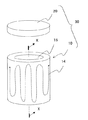
【解決手段】遺伝子および試薬を含む遺伝子検査液を収容するための凹部16を有する有底筒状のセラミック製の基体10と、該基体10の内部に埋設された発熱体14と、上記凹部16を塞ぐように取着された蓋体20とを具備する。
【選択図】 図1PROBLEM TO BE SOLVED: To provide a gene reaction tube and a genetic test apparatus capable of shortening a test time in a genetic test and greatly improving the test efficiency.
A bottomed cylindrical ceramic base 10 having a recess 16 for containing a gene test solution containing a gene and a reagent, a heating element 14 embedded in the base 10, and the recess 16 are provided. And a lid 20 attached so as to close the door.
[Selection] Figure 1
Description
本発明は、遺伝子の増幅に用いられる遺伝子反応管および増幅した遺伝子から遺伝子情報を検出するための遺伝子検査装置に関する。 The present invention relates to a gene reaction tube used for gene amplification and a gene testing apparatus for detecting gene information from the amplified gene.
検査目的の遺伝子の本体であるDNA(デオキシリボ核酸)を有する血液等の検体と試薬とを混合させた遺伝子検査液を収納し、遺伝子の増幅反応を行なうための容器であるマイクロプレートと呼ばれる従来の遺伝子反応管130を図7(a)、(b)に示す。ここで図7(a)は、遺伝子反応管130の断面図、図7(b)は蓋体120を外した状態での斜面図である。
A conventional microplate, which is a container for conducting a gene amplification reaction, containing a genetic test solution in which a reagent such as blood having DNA (deoxyribonucleic acid), which is the main body of a gene to be tested, is mixed The
従来の遺伝子反応管130を使用した遺伝子増幅方法は、代表的なものとしてPCR(ポリメラーゼ・チェイン・リアクション)法、ICAN法、LAMP法等が存在する。近年、非放射性標識を用いた遺伝子の変異を同定するPCR法が注目されている。
Typical gene amplification methods using the conventional
PCR法とはDNAを複製する酵素(耐熱性のDNAポリメラーゼ)を利用して特定のDNA領域を短時間で増幅する方法である。先ず、目的の遺伝子の本体であるDNA(ゲノムDNA等)の領域に対して相補的な塩基配列を持つ遺伝子の断片(プライマー)を合成する。次に、2本鎖のDNAを加熱処理(約90℃)して一本鎖の鋳型DNAに分離し、その後冷却(約50℃)してプライマーを結合させる。そこに熱に安定なDNAポリメラーゼを加え、再度加熱(約70℃)して1本の鋳型DNAを2本に増幅する。この一連の工程を複数繰り返すことにより目的の遺伝子の本体であるDNAを指数関数的に短時間で増幅することができる。 The PCR method is a method of amplifying a specific DNA region in a short time using an enzyme that replicates DNA (heat-resistant DNA polymerase). First, a gene fragment (primer) having a base sequence complementary to a region of DNA (genomic DNA or the like) that is the main body of the target gene is synthesized. Next, the double-stranded DNA is heated (about 90 ° C.) to be separated into single-stranded template DNA, and then cooled (about 50 ° C.) to bind the primer. A heat-stable DNA polymerase is added thereto and heated again (about 70 ° C.) to amplify one template DNA into two. By repeating this series of steps a plurality of times, the DNA that is the main body of the target gene can be amplified exponentially in a short time.
つまり、1回の工程で2本のDNAが複製されるので、これを20回繰り返せば220=で約100万倍に、30回で230=約1億倍に複製できる。しかもこの増幅は短時間でできるという長所がある。 That is, since two DNAs are replicated in one step, if this is repeated 20 times, 2 20 = can be replicated about 1 million times, and 30 times can be replicated 2 30 = about 100 million times. Moreover, this amplification can be performed in a short time.
そして、このようなPCR法により増幅された遺伝子を蛍光検出法によって遺伝子情報を検出することができる。即ち、増幅された遺伝子に特定の物質にのみ結合する化学的なマーキングを施した後、特定波長の紫外線を当てるとマーキング部が反応して蛍光を発するため、施したマーキングの種類により遺伝子の特徴を知ることが可能となる。
近年、遺伝子検査における検査時間の短縮に対する要求が急激に増加している。しかしながら、PCR法による遺伝子増幅反応を行なうプロセスは、目的の遺伝子の本体であるDNAを有する検体とPCR法用試薬とを混合した遺伝子検査液をヒータにより加熱して50〜90℃の範囲で温度を変化させて反応させ、この工程を30〜40回繰り返すことにより行なわれるため、遺伝子検査液が蒸発して液量が減少しやすいものであり、遺伝子検査液の蒸発を防止するために蓋体120を取着させるものの、従来の遺伝子反応管130は基体110および蓋体120がポリプロピレン等のプラスティックから成るために気密性が悪く、遺伝子検査液の蒸発を見越して液量を50μL程度も用いる必要があった。そのため、遺伝子検査液を所望の温度とするのに時間がかかり、検査時間を短縮するのが困難であるという問題点を有していた。
In recent years, there has been a rapid increase in the demand for shortening test time in genetic testing. However, the gene amplification reaction by the PCR method is carried out by heating a genetic test solution obtained by mixing a sample having DNA which is the main body of the target gene and a PCR method reagent with a heater to a temperature in the range of 50 to 90 ° C. This is performed by repeating this
また、従来のポリプロピレン等のプラスティックから成る遺伝子反応管30を恒温槽に投入して、所定の温度にまで遺伝子検査液を上昇させていたが、プラスチックでは熱伝導率が低いため、内部に収容する遺伝子検査液を所望の温度とするのに時間がかかるとともに、遺伝子検査液を温度制御するのが困難であるという問題点も有していた。
In addition, the conventional
さらに、従来においては、増幅を行なった後の遺伝子検査液に対して紫外線を照射して遺伝子検査液の蛍光反応から遺伝子情報を確認する際、増幅反応後の遺伝子検査液を別の容器に移して紫外線を照射し蛍光反応を確認する必要があった。そのため、微量しか検査しない検査液が遺伝子反応管130の凹部にこびりつき、遺伝子反応管130から完全に遺伝子検査液を取り出すことは非常に困難であり、遺伝子検査液を多量に用いる必要があるとともに、非常に作業効率が悪いという問題点があった。
Furthermore, conventionally, when the genetic test solution after amplification is irradiated with ultraviolet rays to confirm the genetic information from the fluorescence reaction of the genetic test solution, the genetic test solution after the amplification reaction is transferred to another container. It was necessary to confirm the fluorescence reaction by irradiating ultraviolet rays. For this reason, a test solution that tests only a small amount sticks to the recess of the
本発明は、上記問題点に鑑み完成されたものであり、その目的は、遺伝子検査における検査時間を短縮して検査効率を大幅に向上させることのできる遺伝子反応管および遺伝子検査装置を提供することにある。 The present invention has been completed in view of the above problems, and an object of the present invention is to provide a gene reaction tube and a genetic test apparatus that can shorten the test time in the genetic test and greatly improve the test efficiency. It is in.
本発明は、遺伝子および試薬を含む遺伝子検査液を収容するための凹部を有する有底筒状のセラミック製の基体と、該基体の内部に埋設された発熱体と、上記凹部を塞ぐように取着され、少なくとも一部が紫外線透過性を有する蓋体とを具備したことを特徴とする。 The present invention provides a bottomed cylindrical ceramic base having a recess for containing a gene testing solution containing a gene and a reagent, a heating element embedded in the base, and the recess so as to close the recess. And a lid that is at least partially transparent to ultraviolet rays.
また、遺伝子および試薬を含む遺伝子検査液を収容するための凹部を有する有底筒状のセラミック製の基体と、該基体の内部に埋設された発熱体と、上記凹部を塞ぐように取着された蓋体とを具備し、上記基体の外側面から凹部の内側面にかけて貫通孔が形成されるとともに、貫通孔を塞ぐように少なくとも一部が紫外線透過性を有する窓部材を取着したことを特徴とする。 Also, a bottomed cylindrical ceramic base having a recess for containing a gene test solution containing a gene and a reagent, a heating element embedded in the base, and the base is attached so as to close the recess. A through-hole is formed from the outer surface of the base to the inner surface of the recess, and at least a part of the window member having ultraviolet transparency is attached so as to close the through-hole. Features.
さらに、上記基体が非イオン伝導性の絶縁層とジルコニア層とを順次積層してなるとともに、上記絶縁層中、ジルコニア層中、または絶縁層とジルコニア層との間のいずれかに白金からなる発熱体を埋設したことを特徴とする請求項1または2に記載の遺伝子反応管。
Further, the base is formed by sequentially laminating a non-ion conductive insulating layer and a zirconia layer, and heat is generated from platinum in the insulating layer, in the zirconia layer, or between the insulating layer and the zirconia layer. The gene reaction tube according to
また、上記遺伝子反応管を用いた本発明の遺伝子検査装置は、遺伝子反応管と、上記蓋体または窓部材に紫外線を入射させるための紫外線照射手段と、上記蓋体または窓部材から出射した光を検知するための光検知手段と、上記発熱体の温度を制御するための温度制御手段とを具備し、上記温度制御手段により遺伝子反応管内に収容された遺伝子検査液中の遺伝子を反応させるとともに、上記紫外線照射手段によって上記蓋体または窓部材から紫外線を透過させて遺伝子検査液に照射することで遺伝子と紫外線との反応によって生じ、蓋体または窓部材から透過して出射された蛍光を光検知手段により検知することを特徴とする。 Further, the gene testing apparatus of the present invention using the gene reaction tube includes a gene reaction tube, ultraviolet irradiation means for making ultraviolet rays incident on the lid or window member, and light emitted from the lid or window member. And a temperature control means for controlling the temperature of the heating element, and reacts the gene in the genetic test solution contained in the gene reaction tube by the temperature control means. The ultraviolet rays are transmitted from the lid or window member by the ultraviolet irradiation means and irradiated to the genetic test solution, and the fluorescence generated by the reaction between the gene and the ultraviolet rays and transmitted through the lid or window member is emitted as light. It is detected by a detection means.
遺伝子および試薬を含む遺伝子検査液を収容するための凹部を有する有底筒状の基体と、該基体の内部に埋設された発熱体と、上記凹部を塞ぐように取着された蓋体とを具備することにより、遺伝子検査における検査時間を短縮して検査効率を大幅に向上させることのできる遺伝子反応管および遺伝子検査装置を提供することが可能となる。 A bottomed cylindrical base having a recess for containing a gene test solution containing a gene and a reagent, a heating element embedded in the base, and a lid attached to close the recess By providing, it becomes possible to provide a gene reaction tube and a gene testing apparatus capable of shortening the testing time in gene testing and greatly improving the testing efficiency.
また、遺伝子および試薬を含む遺伝子検査液を収容するための凹部を有する有底筒状のセラミック製の基体と、該基体の内部に埋設された発熱体と、上記凹部を塞ぐように取着された蓋体とを具備し、上記基体の外側面から凹部の内側面にかけて貫通孔が形成されるとともに、貫通孔を塞ぐように少なくとも一部が紫外線透過性を有する窓部材を取着したことにより、遺伝子検査液に窓部材を通して紫外線を照射することができまた、窓部材から遺伝子検査液の発光状態を確認することが可能となる。 Also, a bottomed cylindrical ceramic base having a recess for containing a gene test solution containing a gene and a reagent, a heating element embedded in the base, and the base is attached so as to close the recess. A through hole is formed from the outer surface of the base to the inner surface of the recess, and at least a part of the window member having ultraviolet transparency is attached so as to close the through hole. In addition, the genetic test solution can be irradiated with ultraviolet rays through the window member, and the light emission state of the genetic test solution can be confirmed from the window member.
また、上記基体が非イオン伝導性の絶縁層とジルコニア層とを順次積層してなるとともに、上記絶縁層中、ジルコニア層中、または絶縁層とジルコニア層との間のいずれかに白金からなる発熱体を埋設したことにより、遺伝子検査液および外気から発熱体が隔離されることにより、発熱体の劣化を防止することが可能となる。 In addition, the base is formed by sequentially laminating a non-ion conductive insulating layer and a zirconia layer, and heat is generated from platinum in the insulating layer, in the zirconia layer, or between the insulating layer and the zirconia layer. By burying the body, it is possible to prevent deterioration of the heating element by isolating the heating element from the genetic test solution and the outside air.
また、上記の何れかに記載の遺伝子反応管と、上記蓋体または窓部材に紫外線を入射させるための紫外線照射手段と、上記蓋体または窓部材から出射した光を検知するための光検知手段と、上記発熱体の温度を制御するための温度制御手段とを具備し、上記温度制御手段により遺伝子反応管内に収容された遺伝子検査液中の遺伝子を反応させるとともに、上記紫外線照射手段によって上記蓋体または窓部材から紫外線を透過させて遺伝子検査液に照射することで遺伝子と紫外線との反応によって生じ、蓋体または窓部材から透過して出射された蛍光を光検知手段により検知することにより、遺伝子検査における検査時間を短縮して検査効率を大幅に向上させることのできる遺伝子反応管および遺伝子検査装置を提供することが可能となる。 Further, the gene reaction tube according to any one of the above, an ultraviolet irradiation means for making ultraviolet rays incident on the lid or window member, and a light detection means for detecting light emitted from the lid or window member And temperature control means for controlling the temperature of the heating element, the temperature control means reacts the gene in the genetic test solution contained in the gene reaction tube, and the ultraviolet irradiation means causes the lid to By irradiating the genetic test solution by transmitting ultraviolet light from the body or window member, it is caused by the reaction between the gene and ultraviolet light, and by detecting the fluorescence transmitted through the lid body or window member by the light detection means, It is possible to provide a gene reaction tube and a gene testing apparatus capable of shortening the testing time in gene testing and greatly improving the testing efficiency.
本発明の遺伝子反応管の実施形態を以下に詳細に説明する。 Embodiments of the gene reaction tube of the present invention will be described in detail below.
図1は本発明の遺伝子反応管の一実施形態を示す斜視図であり、遺伝子および試薬を含む遺伝子検査液を収容するための凹部16を有する有底筒状のセラミック製の基体10と、該基体10の内部に埋設された発熱体14と、上記凹部16を塞ぐように取着され、少なくも一部が紫外線透過性を有する蓋体20とを具備してなる。
FIG. 1 is a perspective view showing an embodiment of a gene reaction tube according to the present invention. A bottomed cylindrical
基体10は、遺伝子および試薬を含む遺伝子検査液を収容するための保持体、ならびに遺伝子検査液へ熱を伝達するための熱伝導体として機能している。
The
なお、本発明において、遺伝子とはDNA内の遺伝情報を含んだ部分のことである。また、ある種のウィルスの場合は、DNA内の遺伝情報を含んだ部分のことである。 In the present invention, a gene is a part including genetic information in DNA. Moreover, in the case of a certain kind of virus, it is a part including genetic information in DNA.
上記基体10は、ZrO2(ジルコニア)質焼結体、Al2O3(アルミナ)質焼結体、Si3N4(窒化珪素)質焼結体、AlN(窒化アルミニウム)質焼結体等のセラミック製であり、セラミックスで形成することにより、耐熱性、耐薬品性が高く、内部に発熱体14を埋設した場合においても、その熱を効率良く遺伝子検査液に伝え、発熱しても割れや欠けが生じることを有効に防止することができる。また、セラミックスの加工精度より内径および外径の公差が1〜5μm以下と非常に高い加工精度で形成することができ、さらには基体10の摩擦係数が低いとともに、剛性が高く、熱膨張係数も低いことから、外部応力や温度変化に対して基体の形状を安定にすることができ、遺伝子反応管30の気密性を非常に高くして、遺伝子検査液の蒸発を著しく抑制することができる。その結果、収容する遺伝子検査液の量を非常に少なくすることができ、検査時間を著しく短縮することができる。また、基体10が耐食性にも非常に優れ、しかも紫外線に対しても安定なものとなり、基体10が遺伝子検査液に侵されたり紫外線によって劣化したりして遺伝子情報の検出の妨げとなるのを抑制することができる。さらに、遺伝子検査液に照射する紫外線や遺伝子検査液から生じた蛍光を内側面で効率よく反射させることができることから、紫外線強度が低下したり蛍光強度が低下するのを有効に抑制して検査精度を向上させることができる。
The
基体10を押出成形やプレス成形、射出成形等により所定形状に成形する際、また必要があれば切削等により高精度な加工をする際、内径および外径の公差を1μm以下と高精度にすることができる。その結果、遺伝子反応管30の形状を安定化することができ、遺伝子検査液に対する紫外線照射効率や蛍光効率を一定に維持して、遺伝子反応管30ごとに遺伝子情報の検出結果が異なることのない高精度の検出が可能となる。また、基体10の外側面と内側面との間の厚みを全周にわたって一定にすることができ、内部に収容する遺伝子検査液の温度制御を容易に行なうことができる。その結果、遺伝子増幅反応の速度を高めることができ検査時間を短縮化することができる。さらに、基体10の内側面において紫外線を等方的に反射することができ、遺伝子検査液に対する紫外線の照射効率を高めて遺伝子情報の検出効率を高めることができる。
When forming the
基体10の凹部16が形成されている一端面は平坦になっているのがよく、これにより蓋体20を安定して取着することができ、蓋体20によって凹部16の気密性を良好にすることができる。
One end surface of the base 10 on which the
また、基体10の内部に埋設された発熱体14は、ニクロム、カンタル合金、白金等の材料を用いることができるが、耐環境性等を考慮すると白金を用いることが好ましい。
The
また、基体10の凹部16を塞ぐように取着された蓋体20は、ガラスやプラスチック等からなり、少なくとも一部が紫外線透過アクリルもしくは紫外線透過ガラス等の紫外線透過性を有することに特定される。なお、プラスチックの場合は遺伝子検査液に化学反応するものは採用できない。
The
これにより、紫外線透過性の蓋体20を介して遺伝子検査液に紫外線を照射することができ、遺伝子検査液から生じた蛍光もこの蓋体20を介して検知することができる。
As a result, the genetic test solution can be irradiated with ultraviolet rays through the
なお、基体10の側面には詳細を後述するような窓部材を形成されていてもよく、紫外線透過性の蓋体20に紫外線を照射することにより、遺伝子検査液から生じた蛍光を窓部材を介して検知することができる。
In addition, a window member whose details will be described later may be formed on the side surface of the
まら、蓋体20が紫外線透過性を有する場合、窓部材は遺伝子検査液から生じた蛍光に対して高い透過率を有しているのが好ましく、蓋体20から紫外線を照射し、遺伝子検査液から生じた蛍光を窓部材から検出することができる。
In addition, when the
次いで、図2基づいて本発明の遺伝子反応管の他の実施形態について説明する。 Next, another embodiment of the gene reaction tube of the present invention will be described with reference to FIG.
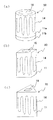
図2(a)、(b)に示すように、本発明の遺伝子反応管の他の実施形態は、上述の図1に示す一実施形態と同様に、基体10と、該基体10の内部に埋設された発熱体14と、上記凹部を塞ぐように取着された蓋体20とを具備し、上記基体10の外側面から凹部16の内側面にかけて貫通孔17が形成されるとともに、貫通孔17を塞ぐように少なくとも一部が紫外線透過性を有する窓部材18を取着したことを特徴とするものである。
As shown in FIGS. 2 (a) and 2 (b), another embodiment of the gene reaction tube of the present invention is similar to the embodiment shown in FIG. It has a buried
これにより、遺伝子検査液に窓部材18を通して紫外線を照射することができ、窓部材18から遺伝子検査液の発光状態を確認することが可能となる。
Accordingly, the genetic test solution can be irradiated with ultraviolet rays through the
窓部材18は、蓋体20と同様にガラスやプラスチック等からなり、少なくとも一部が紫外線透過アクリルもしくは紫外線透過ガラス等の紫外線透過性を有することに特定される。なお、プラスチックの場合は遺伝子検査液に化学反応するものは採用できない。
The
また、窓部材18は、貫通孔17に嵌着することによって基体10に取着されてもよく、基体10の外側面に貫通孔17の開口の周囲に接合することによって基体10に取着されてもよいが、より好ましくは窓部材18が基体10の内側面と面一になるように貫通孔17に嵌着されているのがよい。これにより、貫通孔17と窓部材18とから成る窪みが生じて遺伝子反応液が滞留したり紫外線の照射が妨げられるのを有効に抑制でき、遺伝子の複製反応を良好に進行させることができるとともに、紫外線を遺伝性検査液に均一に照射して遺伝子情報の検出の分解能を向上させることができる。
Further, the
窓部材18を取着する貫通孔17を基体10に設ける場合には、あらかじめ貫通孔17となる部分に孔を形成しておいて焼成する方法、成形後に切削して貫通孔17となる孔を形成した後に焼成する方法、焼成後に研削にて貫通孔17を形成する方法等、いずれの方法を用いてもよい。ただし、図2(b)に示すように、貫通孔17の部位を予め見込んで発熱体14を形成することが重要であり、貫通孔17から3mm程度距離を持たせた状態で発熱体14を形成することが好ましい。これは3mmより短かすぎると、発熱体14が貫通孔17まで通じる可能性があり、また3mmよりも長すぎると加熱効率が悪くなるからである。
When the
さらに、窓部材18が紫外線透過性である場合、蓋体20は遺伝子検査液から生じた蛍光に対して高い透過率を有しているのがよい。これにより、窓部材18から紫外線を照射し、遺伝子検査液から生じた蛍光を蓋体20から検出することができる。また、窓部材18を紫外線に対しておよび遺伝子検査液から生じた蛍光に対して高い透過率を有しているものとすれば、窓部材18から紫外線を照射して遺伝子検査液から生じた蛍光を窓部材18で検出することも可能である。
Furthermore, when the
この場合、窓部材18に加え、上記蓋体20も紫外線透過性を有することが好ましく、蓋体20に紫外線を照射して窓部材18で遺伝子検査液から生じた蛍光を検知することにより、または、窓部材18に紫外線を照射して蓋体20で遺伝子検査液から生じた蛍光を検知することにより、一つの蓋体20または窓部材18に対して紫外線照射手段および光検知手段の両方を設置する必要がないため、蓋体20または窓部材18を非常に小さくすることができ、遺伝子検査装置を小型化することができる。
In this case, in addition to the
また、紫外線の照射方向に対して直角に光検知手段を設置することができるため、紫外線が光検知手段に直接入り込んでノイズとなるのを防止でき、遺伝子情報の検出の分解能をより高くすることができる。 In addition, since the light detection means can be installed at right angles to the irradiation direction of ultraviolet rays, it is possible to prevent ultraviolet rays from directly entering the light detection means and becoming noise, and to further increase the resolution of detection of genetic information. Can do.
さらに、蓋体20が紫外線透過性である場合、窓部材18は遺伝子検査液から生じた蛍光に対して高い透過率を有しているのがよい。これにより、蓋体20から紫外線を照射し、遺伝子検査液から生じた蛍光を窓部材18から検出することができる。
Further, when the
また、図1、図2に示す各実施形態の遺伝子反応管における基体10は、図3(a)〜(c)に示す要部拡大断面図に示すように、母体となるセラミック体の上面に非イオン伝導性の絶縁層とジルコニア層とを順次積層してなるとともに、上記絶縁層中、ジルコニア層中、または絶縁層とジルコニア層との間のいずれかに白金からなる発熱体を埋設することが好ましい。
In addition, the
母体11は、アルミナ質焼結体、ジルコニア質焼結体等の各種セラミックスからなり、ジルコニア質焼結体を用いることが好ましい。これは、発熱体14である白金との積層焼成性がよいからである。
The
ジルコニア焼結体を用いる場合、具体的にはY2O3およびYb2O3、Sc2O3、Sm2O3、Nd2O3、Dy2O3等の希土類酸化物の群から選ばれる少なくとも1種を酸化物換算で1〜30モル%、好ましくは3〜15モル%含有する部分安定化ZrO2あるいは安定化ZrO2が用いられている。また、ZrO2中のZrを1〜20原子%をCeで置換したZrO2を用いることにより、電子伝導性が大きくなり、応答性がさらに改善されるといった効果がある。さらに、焼結性を改善する目的で、上記ZrO2に対して、Al2O3やSiO2を添加含有させることができるが、多量に含有させると、高温におけるクリープ特性が悪くなることから、Al2O3およびSiO2の添加量は総量で5重量%以下、特に2重量%以下であることが望ましい。 When the zirconia sintered body is used, specifically, it is selected from the group of rare earth oxides such as Y 2 O 3 and Yb 2 O 3 , Sc 2 O 3 , Sm 2 O 3 , Nd 2 O 3 , and Dy 2 O 3. 1 to 30 mol% in terms of oxide of at least one element, preferably the partially stabilized ZrO 2 or stabilized ZrO 2 containing 3 to 15 mol% are used. Further, by using ZrO 2 in which 1 to 20 atomic% of Zr in ZrO 2 is substituted with Ce, there is an effect that electron conductivity is increased and responsiveness is further improved. Furthermore, for the purpose of improving the sinterability, Al 2 O 3 and SiO 2 can be added to ZrO 2 , but if it is contained in a large amount, the creep properties at high temperatures deteriorate, The total amount of Al 2 O 3 and SiO 2 added is desirably 5% by weight or less, particularly 2% by weight or less.
母体11の表面に形成される絶縁層12としては、それ自体が非イオン伝導性を有することが必要である。これは、母体11と白金からなる発熱体14とを電気的に完全に分離し絶縁化するためである。この絶縁層12としては、アルミナ、スピネル、フォルステライト、ガラス等のセラミック材料が好適に用いられる。また、絶縁層12としてガラスを用いる場合には、耐熱性の観点から、BaO、PbO、SrO、CaO、CdOのうちの少なくとも1種を5重量%以上含有するガラス、特に、結晶化ガラスであることが望ましい。
The insulating
また、絶縁層12の上面に積層するジルコニア層13としては、主成分であるジルコニアに対してY2O3およびYb2O3、Sc2O3、Sm2O3、Nd2O3、Dy2O3等の希土類酸化物の群から選ばれる少なくとも1種の酸化物を酸化物換算で1〜30モル%、特に強度を高める上で3〜15モル%の割合で含有する部分安定化ZrO2あるいは安定化ZrO2が好適に用いられる。また、ZrO2中のZrを1〜20原子%のCeで置換したZrO2も好適に用いることが可能であるが、特に、母体11を構成する材料と同じ熱膨張特性を有することが望ましいことから、母体11のジルコニアと同一の組成のものが最も好ましい。
As the
さらに、このジルコニア層13はヒータの保温性の観点から100〜200μmの厚みとすることが好ましく、ジルコニア層13を形成することで、発熱体14を外気にさらすことなく保護でき、発熱体14の耐久性を劣化させることがない。
Furthermore, the thickness of the
このように、基体10として、母体11の上面に絶縁層12、ジルコニア層13を順次積層したものを用いることで、母体11と発熱体14を電気的に分離させることが可能となり、発熱体14を外気に曝すことなく、使用上安定した特性を継続して得ることができる。
As described above, by using the
このような構造を成す基体10に発熱体14を埋設する場合、発熱体14は、図3(a)に示すように絶縁層12中に埋設する場合、図3(b)に示すようにジルコニア層13中に埋設する場合、または図3(c)に示すように絶縁層12とジルコニア層13との間に埋設する場合の何れかの構造をなし、発熱体14として白金を用いる。
When the
発熱体14として白金を用いることで、積層後に焼成を行うが、大気中で安定な白金を用いることが、焼成後の剥離や、変形、クラックが生じにくくなることと、安定した発熱特性を継続して行えるためである。
Firing is performed after lamination by using platinum as the
特に、図3(a)に示すように、発熱体14を絶縁層12中に埋設することが好ましく、DNA検査液の入っている凹部へ熱が伝わりやすくなることと、発熱体を外部から守りやすい構造となっているからである。
In particular, as shown in FIG. 3A, it is preferable to embed the
また、かかる構造において、母体11の表面から発熱体14までの絶縁層12の厚さL1が1〜100μm、特に5〜50μm、さらには10〜40μmであることが好ましい。これは、上記厚さがL1が1μmよりも薄いと、母体11と絶縁層12が熱応力で剥離する可能性が高くなるからである。また、厚みL1 が100μmを超えると、発熱体14による加熱効率が低下し、活性化時間が長くなるとともに、母体11と絶縁層12間に生じる熱応力に起因して絶縁層が剥離しやすく、ヒータの抵抗の増加率が大きくなるためである。
In such a structure, the thickness L1 of the insulating
さらに、図3(c)のように発熱体14がジルコニア層13中に埋設される場合、母体11から発熱体14までの絶縁層12およびジルコニア層13との合計厚さL2は100μm以下であることが重要である。これは、厚みL2が100μmを超えると、発熱体14による加熱効率が低下し、活性化時間が長くなるためである。
Further, when the
以上、ジルコニアを用いて説明してきたが、これに限ることなく、アルミナ等のセラミックスを用いることが可能である。 As described above, the description has been given using zirconia. However, the present invention is not limited to this, and ceramics such as alumina can be used.
ここで、発熱体14を埋設した基体10を作製する方法を図4に基づいて説明する。ここでは、基体10としてジルコニア質焼結体からなる母体11に絶縁層12、ジルコニア層13を積層したものを例に説明する。
Here, a method of manufacturing the
まず、図4(a)に示すような母体11を作製する。この母体11は、酸素イオン伝導性を有するジルコニア固体電解質粉末に対して、適宜、成形用有機バインダーを添加して押出成形や、静水圧成形(ラバープレス)あるいはプレス形成などの周知の方法により一端が封止された母体11を作製する。
First, the base 11 as shown in FIG. The
この時、ジルコニア粉末に対して安定化剤としてY2O3およびYb2O3、Sc2O3、Sm2O3、Nd2O3、Dy2O3等の希土類酸化物の群から選ばれる少なくとも1種を酸化物換算で1〜30モル%、好ましくは3〜15モル%の割合で添加した混合粉末、あるいはジルコニアと上記安定化剤との共沈原料粉末が用いられる。また、ZrO2中のZrを1〜20原子%をCeで置換したZrO2粉末、または共沈原料を用いることもできる。 At this time, Y 2 O 3 and Yb 2 O 3 , Sc 2 O 3 , Sm 2 O 3 , Nd 2 O 3 , Dy 2 O 3 and the like are selected as a stabilizer for the zirconia powder. A mixed powder obtained by adding at least one of the above in an amount of 1 to 30 mol%, preferably 3 to 15 mol% in terms of oxide, or a coprecipitation raw material powder of zirconia and the stabilizer is used. It is also possible to use ZrO 2 powder or coprecipitated material, a 1-20 atomic% of Zr in ZrO 2 was replaced by Ce.
さらに、焼結性を改善する目的で、上記固体電解質粉末にAl2O3やSiO2を5重量%以下、特に2重量%以下の割合で添加することも可能である。 Furthermore, for the purpose of improving the sinterability, Al 2 O 3 or SiO 2 can be added to the solid electrolyte powder in a proportion of 5 wt% or less, particularly 2 wt% or less.
次に、図4(b)に示すようなヒータ素体15を形成する。ヒータ素体15は、まず、上記と同様なジルコニア粉末を用いてドクターブレード法、押し出し成形法、プレス法などにより所定厚さのジルコニア層13用グリーンシートを作製する。
Next, a
そして、非イオン伝導性を有する絶縁層12を形成し得るアルミナ、スピネル、フォルステライト、ガラス等のセラミック粉末に、適宜成形用有機バインダーを添加してスラリーを調製し、このスラリーを上記ジルコニア層13用グリーンシートに塗布し、その後、白金粉末を含む導電性ペーストを発熱体パターンにスクリーン印刷法、パット印刷法、ロール転写法等により印刷した後、その上にさらにスラリーを塗布し、乾燥することにより、発熱体14が埋設された絶縁層12とジルコニア層13用グリーンシートとの積層体からなるヒータ素体15を作製できる。
Then, a slurry is prepared by appropriately adding an organic binder for molding to ceramic powder such as alumina, spinel, forsterite, glass or the like that can form the insulating
また、他の方法としては、ジルコニア層13用グリーンシート、絶縁層12用グリーンシートを作製し、そのいずれか一方に白金の発熱体14を印刷塗布した後、積層しても同様な積層体からなるヒータ素体15を作製することができる。
As another method, a green sheet for the
上記の各グリーンシートの厚みとしては60〜600μm、特に100〜300μmが好ましい。シートの厚みが60μmより薄いとシートの取り扱いが困難であり、600μmを超えるとシートの母体11の成形体表面への巻き付けが難しくなるためである。
The thickness of each green sheet is preferably 60 to 600 μm, particularly preferably 100 to 300 μm. This is because if the thickness of the sheet is thinner than 60 μm, it is difficult to handle the sheet, and if it exceeds 600 μm, it is difficult to wrap the sheet around the molded body surface of the
次に、図4(c)に示すように、上記母体11の表面に、ヒータ素体15を巻き付けて円筒状積層体を作製する。この際、ヒータ素体15を母体に巻き付けるには、ヒータ素体15と母体11との間にアクリル樹脂や有機溶媒などの接着剤を介在させて接着させたり、あるいはローラ等で圧力を加えながら機械的に接着することができる。この時、巻き付けされたヒータ素体15の合わせ目は、焼成時の収縮を考慮し、シート端部同志を重ねるか、あるいは所定の間隔をおいて接着してもよい。
Next, as shown in FIG. 4C, a
なお、ヒータ素体15を巻き付ける場合、絶縁層12用グリーンシートとジルコニア層13用グリーンシートとの積層体を巻き付ける方法以外に、絶縁層12用グリーンシートを巻き付けた後に、ジルコニア層13用グリーンシートを巻き付けることも可能である。
In addition, when winding the heater element |
そして、上記の円筒状積層体を基体10を構成する母体11およびヒータ素体15における絶縁層12用グリーンシートおよびジルコニア層13用グリーンシートが同時に焼成可能な温度で焼成することにより、ヒータ素体15と母体11とが一体化された遺伝子反応管30が作製される。
Then, the above-mentioned cylindrical laminate is fired at a temperature at which the green sheet for the insulating
焼成条件としては、アルゴンガス等の不活性雰囲気中あるいは大気中1300〜1700℃で1〜10時間程度焼成することが望ましい。 As firing conditions, firing in an inert atmosphere such as argon gas or in the air at 1300 to 1700 ° C. for about 1 to 10 hours is desirable.
なお、図3(b)に示すように、発熱体14がジルコニア層13内に埋設した場合には、上記ヒータ素体15を作製する時に、ジルコニア層13用グリーンシートの表面に、白金ペーストを塗布した後、ジルコニア層13用のグリーンシートを積層するかまたはスラリーを塗布した後、さらに絶縁層12用のグリーンシートを積層するか、またはスラリーを塗布することによりヒータ素体15を作製した後、上記と同様な方法で巻き付け、同時焼成することにより作製することができる。
As shown in FIG. 3B, when the
また、図3(c)に示すように、発熱体14が絶縁層12とジルコニア層13との間に埋設した場合には、上記ヒータ素体15を作製する時に、ジルコニア層13用グリーンシートの表面に、白金ペーストを塗布した後、絶縁層12用のスラリーを塗布するか、またはグリーンシートを積層してヒータ素体15を作製した後、上記と同様な方法で巻き付け、同時焼成して作製することができる。
As shown in FIG. 3C, when the
次に、本発明の基体の様々な形状を図5を用いて説明する。 Next, various shapes of the substrate of the present invention will be described with reference to FIG.
図5(a)は基体50が円筒状のパイプ11aと底板11bからなる場合である。これは、円筒状パイプ11aを押し出し成形にて加工して、別に成形した底板11bをとりつけたあと、ヒータ素体15とともに一括で焼成することにより得られる。
FIG. 5A shows a case where the
また、円筒状パイプ11aとヒータ素体15を積層し焼成した後、別に焼成した底板11bをハンダ、無機接着剤、低融点ガラス等を用いて固定する方法でもよい。また、固定方法は遺伝子反応管の使用温度が最大100度程度なので、硬化後のガラス転移温度が100℃以上となる樹脂系の接着剤を用いることも可能である。ただし、この場合は、検査液と反応しないような材質もしくは、接着剤が検査液に直接接触しないような構造とする必要がある。
Alternatively, after the
図5(b)は母体11の外側面形状が円断面ではなく多角形断面の場合であり、図5(c)は母体11の外側面形状が多角形断面であり、かつ内側面形状も多角形断面の場合である。
FIG. 5B shows a case where the outer surface shape of the
本発明は外側面形状、内側面形状のいかんを問わず、凹部16を有していれば、同一の効果を奏することができる。
The present invention can produce the same effect as long as it has the
より好ましくは、基体10の外側面および内側面(凹部16の内側面)は円筒面とされているのがよい。これにより、基体10を容易に加工することが可能となり、基体10を押出成形やプレス成形,射出成形等により所定形状に成形する際、また必要があれば切削等により高精度な加工をする際、内径および外径の公差を1μm以下と高精度にすることができる。その結果、遺伝子反応管30の形状を安定化することができ、遺伝子検査液に対する紫外線照射効率や蛍光効率を一定に維持して、遺伝子反応管30ごとに遺伝子情報の検出結果が異なることのない高精度の検出が可能となる。また、基体10の外側面と内側面との間の厚みを全周にわたって一定にすることができ、基体10の外側面から内側面に至る熱伝導時間を全周にわたって均一にして内部に収容する遺伝子検査液の温度制御を容易に行なうことができる。その結果、遺伝子増幅反応の速度を高めることができ検査時間を短縮化することができる。さらに、基体10の内側面において紫外線を等方的に反射することができ、遺伝子検査液に対する紫外線の照射効率を高めて遺伝子情報の検出効率を高めることができる。
More preferably, the outer side surface and the inner side surface (the inner side surface of the recess 16) of the
次に、図6を用いて本発明の遺伝子反応管を用いた遺伝子検査装置について説明する。 Next, a genetic test apparatus using the gene reaction tube of the present invention will be described with reference to FIG.
上記説明してきた遺伝子反応管30と、紫外線透過性の蓋体20または紫外線透過性の窓部材17に紫外線を入射させるための紫外線照射手段81と、蓋体20または窓部材17から出てきた光を検知するための光検知手段82と、遺伝子反応管30の温度を制御するための温度制御手段83とを具備することにより本発明の遺伝子検査装置80となる。
The
そして、温度制御手段83により遺伝子反応管30内の遺伝子検査液中の遺伝子を反応させるとともに、紫外線照射手段81によって紫外線を紫外線透過性の蓋体20または紫外線透過性の窓部材18を透過させて遺伝子検査液に照射し、遺伝子検査液中の遺伝子の紫外線との反応により生じて蓋体20または窓部材18を透過して出てきた蛍光を光検知手段82により検知することにより、遺伝子反応管内30に遺伝子検査液を収納した状態で遺伝子の反応および遺伝子情報の検出を連続して、または同時に行なうことができ、その結果、遺伝子検査における検査時間を大幅に短縮することができるとともに遺伝子情報のより高精度な検出を行なうことができる。
Then, the temperature control means 83 causes the gene in the genetic test solution in the
ここで、紫外線照射手段81とは、紫外線を発光する装置にライトガイドを取り付けて、指定した一部分にのみ紫外線を当てられる、一例として紫外線照射装置を用いることが望ましい。紫外線を広域に発生させると、目に紫外光が入り失明等の危険性があるので、この方法がのぞましことと、市販の安価な装置が販売されており、比較的容易に入手できるからである。 Here, as the ultraviolet irradiation means 81, it is desirable to use an ultraviolet irradiation device as an example in which a light guide is attached to a device that emits ultraviolet rays and ultraviolet rays can be applied only to a specified portion. If ultraviolet rays are generated over a wide area, there is a risk of blindness entering the eyes, so this method is not recommended, and commercially available inexpensive devices are on the market and are relatively easily available. It is.
次に、光検知手段82としては、CCDカメラを用いることが望ましい。遺伝子の紫外線との反応により生じた蛍光を確認するには、特に高価なカメラでなくとも市販のCCDカメラで十分である。しかし、更なる検査確認のためには紫外線対応CCDカメラを用いることがより望ましく、これはCCD自体に紫外光を可視光に変換するコーティングを施す方法で、遺伝子検査液の反応を確認することができる。 Next, it is desirable to use a CCD camera as the light detection means 82. In order to confirm the fluorescence generated by the reaction of the gene with ultraviolet rays, a commercially available CCD camera is sufficient even if it is not an expensive camera. However, it is more desirable to use a UV-compatible CCD camera for further inspection confirmation, which is a method of applying a coating that converts ultraviolet light to visible light on the CCD itself, and confirming the reaction of the genetic test solution. it can.
さらに、上記温度制御手段83が遺伝子反応管の温度をモニタして温度調節を一定にしかも細かく調整できるフィードバック機能を備えることが好ましい。遺伝子反応管の温度は遺伝子反応管の内部に温度センサを入れ込む方法がある。温度センサからの温度を温度制御手段83にて発熱体に電力を与えてフィードバックする方法である。 Furthermore, it is preferable that the temperature control means 83 has a feedback function that allows the temperature of the gene reaction tube to be monitored and the temperature control to be adjusted to be constant and fine. As for the temperature of the gene reaction tube, there is a method of inserting a temperature sensor inside the gene reaction tube. In this method, the temperature from the temperature sensor is fed back to the heating element by the temperature control means 83.
本発明の遺伝子反応管と従来の遺伝子反応管との検査効率を確認するための評価を以下のように行なった。 Evaluation for confirming the examination efficiency of the gene reaction tube of the present invention and the conventional gene reaction tube was performed as follows.
先ず、本発明の遺伝子反応管として、図1に示すような中央部に凹部16が形成された外形が円柱型で、全長10mm、外径2mm、内径126μm、凹部16の深さ3mmのジルコニア質焼結体から成る基体10を準備した。
First, as a gene reaction tube of the present invention, the outer shape in which a
基体10は、図3に示すように母体11、絶縁層12、ジルコニア層13から形成されており、先ず、共沈法によって作製された平均粒径が0.8μmの5モル%Y2O3含有のジルコニア粉末にポリビニルアルコール溶液を添加して坏土を作製し、プレス成形により外径が5mm、内径が3mmの一端を封じた中空の母体11となる成形体を作製した。
As shown in FIG. 3, the
また、上記ジルコニア粉末にポア形成剤として、市販の3μmのポリエチレン粉末を加え、さらにポリビニルアルコール溶液を添加してスラリーを作製し、ドクターブレード法によって種々の厚さのジルコニア層13用グリーンシートを作製した。
In addition, a commercially available 3 μm polyethylene powder is added to the zirconia powder as a pore forming agent, and a polyvinyl alcohol solution is further added to prepare a slurry, and green sheets for the
さらに、平均粒径が0.5μmのスピネル粉末にポリエチレン粉末を加えて絶縁層12形成用のスラリーを調製した。
Furthermore, a slurry for forming the insulating
上記ジルコニア層13用グリーンシートの表面に、スピネルの絶縁層12形成用のスラリーを種々の厚さで塗布乾燥後、その表面に白金粉末の導体ペーストをスクリーン印刷により焼成後の厚さが約10μmとなるように発熱体14となるパターンに印刷塗布した。その後、発熱体14となるパターンの表面に、スピネルの絶縁層12形成用のスラリーを種々の厚さで塗布して、シート状積層体からなるヒータ素体を作製した。そして、上記の母体11に対してヒータ素体を巻き付け円筒状積層体を作製した。その後、この円筒状積層体を大気中、1500℃で2時間焼成した。
The surface of the green sheet for the
次に、蓋体20をほう珪酸ガラスで図1に示すような円板形に作製し、上記基体10と蓋体20とで本発明実施例の遺伝子反応管30を作製した。
Next, the
そして、目的の遺伝子である2本鎖DNAを含むヒトの血液からDNA断片を抽出した検体と、周知のDNA合成方法によって作成した、この目的の遺伝子に対して相補的な塩基配列を持つプライマーと、耐熱性DNAポリメラーゼ(TaKaRa Ex Taq タカラバイオ社製)とを混合した遺伝子検査液となる試薬をDNA基体10の凹部16に注入し、基体10の一端面に直径2mm、高さ1mmの円柱状の石英の蓋体をエポキシ樹脂で凹部16を覆うように接着することにより試料を作製した。
A sample obtained by extracting a DNA fragment from human blood containing double-stranded DNA, which is the target gene, and a primer having a base sequence complementary to the target gene, prepared by a known DNA synthesis method Then, a reagent to be a genetic test solution mixed with heat-resistant DNA polymerase (TaKaRa Ex Taq manufactured by Takara Bio Inc.) is injected into the
次にこの試料を、ヒータで温度を調整することによって、95℃の温度で30秒反応させた後、55℃の温度で30秒反応させ、次に75℃の温度で30秒反応させた。この一連の工程を1サイクルとし、合計40サイクル繰り返した。 Next, this sample was reacted at a temperature of 95 ° C. for 30 seconds by adjusting the temperature with a heater, then reacted at a temperature of 55 ° C. for 30 seconds, and then reacted at a temperature of 75 ° C. for 30 seconds. This series of steps was defined as one cycle, and was repeated 40 times in total.
このようにして反応させた遺伝子検査液に対して、蓋体20から紫外線を入射し、遺伝子検査液の蛍光反応によって出射した出射光を蓋体20を通して受光機によって検出することにより、遺伝子増幅反応が正しく行なわれているか検査した。
The gene test solution reacted in this manner is irradiated with ultraviolet light from the
また、比較例として、図7に示すような従来の遺伝子反応管130を準備した。全長30mm、外周の直径10mm、開孔部の内径9.5mm、内径の凹部深さ26mmの逆円錐型のポリプロピレン製の基体110と、直径10mm、高さ0.5mmのポリプロピレン製の蓋体120とから成る従来の遺伝子反応管130を用いて、上記と同様に40サイクルの遺伝子増幅反応を行った。
As a comparative example, a conventional
加熱方法は、遺伝子反応管130を恒温槽に投入して、槽内に設置したヒータにより加熱した。
As a heating method, the
この比較例の遺伝子検査液を蛍光検出法により蛍光検出を行うため、基体から遺伝子検査液を取り出して蛍光セルに移した後、遺伝子検査液へ紫外線を入射し、遺伝子検査液の蛍光反応によって出射した出射光を受光機により検出することにより、遺伝子増幅反応が正しく行われているか検査した。 In order to detect the fluorescence of the gene test solution of this comparative example by the fluorescence detection method, the gene test solution is taken out from the substrate and transferred to the fluorescence cell, and then ultraviolet rays are incident on the gene test solution and emitted by the fluorescence reaction of the gene test solution. By detecting the emitted light with a light receiver, it was examined whether the gene amplification reaction was performed correctly.
そして、このような手順で行なった遺伝子増幅反応の検査について、遺伝子増幅反応が完了してから蛍光検出法により蛍光検出を完了するまでの時間をストップウォッチにて測定することにより、検査時間の評価を行った。 Then, for the examination of the gene amplification reaction performed in such a procedure, the time from the completion of the gene amplification reaction to the completion of fluorescence detection by the fluorescence detection method is measured by a stopwatch, thereby evaluating the examination time. Went.
表1に評価結果を示す。
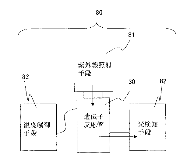
表1より、、本発明の実施例である遺伝子反応管30を用いた場合、10個の測定に対して50分となり、検査時間が非常に短縮できることがわかった。
From Table 1, when the
これに対し、比較例である遺伝子反応管130を用いた場合、10個の測定に対して合計248分もの検査時間が必要であった。
On the other hand, when the
なお、本評価において実施例、比較例のいずれも蛍光が十分に検出されており、特に本発明の遺伝子反応管を用いた試料では遺伝子増幅反応が比較例よりも進んでいるのが確認され、遺伝子増幅反応においても本発明の遺伝子反応管30を用いることにより反応時間を短縮できることがわかった。
In this evaluation, fluorescence was sufficiently detected in both the examples and comparative examples, and it was confirmed that the gene amplification reaction proceeded more than the comparative examples particularly in the sample using the gene reaction tube of the present invention. It was found that the reaction time can be shortened also in the gene amplification reaction by using the
10 基体
11 母体
12 絶縁層
13 ジルコニア層
14 発熱体
15 ヒータ素体
16 凹部
17 貫通孔
18 窓部材
20 蓋体
30 遺伝子反応管
40、50、60、70 基体
80 遺伝子検査装置
81 紫外線照射手段
82 光検知装置
83 温度制御手段
110 基体
120 蓋体
130 遺伝子反応管
DESCRIPTION OF
Claims (4)
Priority Applications (1)
| Application Number | Priority Date | Filing Date | Title |
|---|---|---|---|
| JP2004119763A JP2005295942A (en) | 2004-04-15 | 2004-04-15 | Gene reaction tube and genetic test apparatus using the same |
Applications Claiming Priority (1)
| Application Number | Priority Date | Filing Date | Title |
|---|---|---|---|
| JP2004119763A JP2005295942A (en) | 2004-04-15 | 2004-04-15 | Gene reaction tube and genetic test apparatus using the same |
Publications (1)
| Publication Number | Publication Date |
|---|---|
| JP2005295942A true JP2005295942A (en) | 2005-10-27 |
Family
ID=35328237
Family Applications (1)
| Application Number | Title | Priority Date | Filing Date |
|---|---|---|---|
| JP2004119763A Pending JP2005295942A (en) | 2004-04-15 | 2004-04-15 | Gene reaction tube and genetic test apparatus using the same |
Country Status (1)
| Country | Link |
|---|---|
| JP (1) | JP2005295942A (en) |
Citations (5)
| Publication number | Priority date | Publication date | Assignee | Title |
|---|---|---|---|---|
| JPH0686941A (en) * | 1992-07-01 | 1994-03-29 | Shuji Ueda | Ceramic heater-cooler |
| JPH0699085A (en) * | 1992-07-01 | 1994-04-12 | Shuji Ueda | Ceramic heater/cooler |
| US5504007A (en) * | 1989-05-19 | 1996-04-02 | Becton, Dickinson And Company | Rapid thermal cycle apparatus |
| WO2000077253A1 (en) * | 1999-06-16 | 2000-12-21 | Hitachi, Ltd. | Apparatus and method for gene examination |
| WO2004029241A1 (en) * | 2002-09-24 | 2004-04-08 | Matsushita Electric Industrial Co., Ltd. | Method of amplifying nucleic acid by electromagnetic induction heating and reaction container and reaction device to be used therein |
-
2004
- 2004-04-15 JP JP2004119763A patent/JP2005295942A/en active Pending
Patent Citations (5)
| Publication number | Priority date | Publication date | Assignee | Title |
|---|---|---|---|---|
| US5504007A (en) * | 1989-05-19 | 1996-04-02 | Becton, Dickinson And Company | Rapid thermal cycle apparatus |
| JPH0686941A (en) * | 1992-07-01 | 1994-03-29 | Shuji Ueda | Ceramic heater-cooler |
| JPH0699085A (en) * | 1992-07-01 | 1994-04-12 | Shuji Ueda | Ceramic heater/cooler |
| WO2000077253A1 (en) * | 1999-06-16 | 2000-12-21 | Hitachi, Ltd. | Apparatus and method for gene examination |
| WO2004029241A1 (en) * | 2002-09-24 | 2004-04-08 | Matsushita Electric Industrial Co., Ltd. | Method of amplifying nucleic acid by electromagnetic induction heating and reaction container and reaction device to be used therein |
Similar Documents
| Publication | Publication Date | Title |
|---|---|---|
| TWI397567B (en) | Fusible conductive ink for use in manufacturing microfluidic analytical systems | |
| US6984516B2 (en) | Multilayered microfluidic DNA analysis system and method | |
| CN100350248C (en) | A direct immunosensor and assay | |
| US20190032114A1 (en) | Point-of-care nucleic acid amplification and detection | |
| TWI230257B (en) | Integrated analytical biochip and manufacturing method thereof | |
| EP1463380A1 (en) | Ceramic heater | |
| US20080026430A1 (en) | Instrument for heating and cooling | |
| EP1108472A2 (en) | Advanced thermal gradient DNA chip (ATGC), it's manufacture method and method for carrying out biochemical reactions | |
| TW202043450A (en) | System and method for integrated sensor cartridge | |
| CN112740016A (en) | Flow cell and methods related thereto | |
| JP2005295942A (en) | Gene reaction tube and genetic test apparatus using the same | |
| TWI355487B (en) | Ceramic micro well plate and forming method thereo | |
| US20190176156A1 (en) | Thermocycling system, composition, and microfabrication method | |
| CN109764992A (en) | A kind of residual stress lossless detection method for 3D printing zirconia ceramics structure | |
| CN106053576A (en) | Zirconium-based sensor and organic volatile matter detection device with same | |
| JP4014250B2 (en) | Carbon dioxide sensor | |
| JP2008067622A (en) | Cell capture device and temperature control method for cell capture device | |
| JP2006105987A (en) | Manufacturing method of analysis module having accessible electrically conductive contact pad for microfluidic analytical system | |
| JP2000271474A (en) | Small-sized chemical reactor | |
| Vasiliev et al. | Gas sensors based on MEMS structures made of ceramic ZrO2/Y2O3 material | |
| Zhou et al. | Laser-induced graphene heater for DNA amplification and CRISPR-Cas9 biosensing | |
| CN104515755A (en) | Solid quantum dot microarray chip sensor and manufacturing method thereof | |
| JP2012187054A (en) | Nucleic acid amplification reaction apparatus | |
| JP4721593B2 (en) | Oxygen sensor | |
| US20090320617A1 (en) | Device and Method for the Adjustment of a Temperature of a Liquid |
Legal Events
| Date | Code | Title | Description |
|---|---|---|---|
| A621 | Written request for application examination |
Effective date: 20070319 Free format text: JAPANESE INTERMEDIATE CODE: A621 |
|
| A131 | Notification of reasons for refusal |
Effective date: 20100126 Free format text: JAPANESE INTERMEDIATE CODE: A131 |
|
| A521 | Written amendment |
Effective date: 20100325 Free format text: JAPANESE INTERMEDIATE CODE: A523 |
|
| A02 | Decision of refusal |
Free format text: JAPANESE INTERMEDIATE CODE: A02 Effective date: 20100622 |