JP2005295891A - Seedling guide apparatus in transplanter - Google Patents
Seedling guide apparatus in transplanter Download PDFInfo
- Publication number
- JP2005295891A JP2005295891A JP2004116920A JP2004116920A JP2005295891A JP 2005295891 A JP2005295891 A JP 2005295891A JP 2004116920 A JP2004116920 A JP 2004116920A JP 2004116920 A JP2004116920 A JP 2004116920A JP 2005295891 A JP2005295891 A JP 2005295891A
- Authority
- JP
- Japan
- Prior art keywords
- seedling
- guide
- seedling guide
- apron
- end portion
- Prior art date
- Legal status (The legal status is an assumption and is not a legal conclusion. Google has not performed a legal analysis and makes no representation as to the accuracy of the status listed.)
- Granted
Links
- 210000000078 claw Anatomy 0.000 claims description 24
- 238000007790 scraping Methods 0.000 claims description 14
- 241000209094 Oryza Species 0.000 description 4
- 235000007164 Oryza sativa Nutrition 0.000 description 4
- 230000005540 biological transmission Effects 0.000 description 4
- 235000009566 rice Nutrition 0.000 description 4
- 239000002689 soil Substances 0.000 description 4
- 238000009792 diffusion process Methods 0.000 description 3
- 229910001220 stainless steel Inorganic materials 0.000 description 2
- 239000010935 stainless steel Substances 0.000 description 2
- 241000196324 Embryophyta Species 0.000 description 1
- 238000005452 bending Methods 0.000 description 1
- 238000006073 displacement reaction Methods 0.000 description 1
- 238000000605 extraction Methods 0.000 description 1
- 239000000463 material Substances 0.000 description 1
- 238000000034 method Methods 0.000 description 1
- 230000000149 penetrating effect Effects 0.000 description 1
- 239000011347 resin Substances 0.000 description 1
- 229920005989 resin Polymers 0.000 description 1
Images
Landscapes
- Transplanting Machines (AREA)
Abstract
Description
本発明は、苗載台を左右往復動可能に支持する摺動レール部と苗受け部とからなるエプロンを備え、このエプロンに設けたマット苗の掻き取り口から、植付爪によって掻き取った苗を植付け方向に案内する苗ガイドを備えた田植機等の移植機における苗ガイド装置に
関する。
The present invention comprises an apron comprising a slide rail portion and a seedling receiving portion that supports a seedling stage so as to be capable of reciprocating left and right, and a seedling scraped off by a planting claw from a mat seedling scraping opening provided on the apron. The present invention relates to a seedling guide device in a transplanting machine such as a rice transplanter provided with a seedling guide for guiding the plant in the planting direction.
従来の田植機等の移植機においては、苗載台の下端部を摺動自在に受け止める摺動レール(エプロン)を設け、この摺動レールに植付爪が通過する苗取り出し口を形成すると共に、苗取り出し口の縁部に沿って苗取り出し口ガイドを取り付け、且つ苗取り出し口の下方側に植付爪の移動軌跡に沿って取り出し苗の拡がりを阻止する左右の苗ガイドを設け、更に、左右の苗ガイドの奥側端縁に沿うステンレス材からなるガイド板の基端部を、前記苗取り出し口ガイドと摺動レールとの間に挟み込み支持するよう構成したものが知られている(例えば、特許文献1参照。)。
しかし、上述したステンレス材からなるガイド板の基端部を、実際に苗取り出し口ガイドと摺動レールとの間に挟み込んで支持する際は、側面視で略くの字形に折り返し成形されたガイド板の基端部を、苗取り出し口ガイドの縁に沿う平面視コの字形に形成した縦板状の開口形成部の内奥側面と、摺動レールのフレーム部の一側面との間に挟み込んだ状態で、苗取り出し口ガイドと左右の苗ガイドの取付け部とを摺動レールの苗受け止め用縦面部に共締め固定しなければならず、極めて組立作業性が悪いことから、当該ガイド板の位置決め保持を目的として、苗取り出し口ガイドの開口形成部の内奥側面に形成した突起と、ガイド板に設けた係合孔を嵌合させるよう構成しているが十分なものではなかった。また、前記ガイド板を単独で位置調節することができなかった。 However, when the base end portion of the above-described guide plate made of stainless steel is actually sandwiched and supported between the seedling outlet guide and the slide rail, the guide is folded back into a generally U shape in side view. The base end portion of the plate is sandwiched between the inner back side surface of the vertical plate-shaped opening forming portion formed in a U shape in plan view along the edge of the seedling outlet guide and one side surface of the frame portion of the slide rail. In this state, the seedling outlet guide and the left and right seedling guide mounting parts must be fastened together and fixed to the vertical surface for receiving seedlings of the slide rail, and the assembly workability is extremely poor. For the purpose of positioning and holding, the projection formed on the inner back side of the opening forming part of the seedling outlet guide and the engaging hole provided in the guide plate are fitted, but this is not sufficient. Further, the position of the guide plate could not be adjusted alone.
本発明は、上記課題を解決することを目的として創案したものであって、左右往復動可能に苗載台の下端部を支持する摺動レール部と苗受け部とを備えたエプロンに掻き取り口を設け、該掻き取り口から植付爪によって掻き取った苗の前部に当接して、当該掻き取り苗の前方への倒れを抑制する第一苗ガイドと、植付爪によって掻き取った苗の拡散を抑制する第二苗ガイドとを備えた移植機において、前記第二苗ガイドにおけるエプロンへの取り付け部の前方に嵌合部を設け、該嵌合部に第一苗ガイドの基端部を弾持した状態で螺着することを第1の特徴としている。 The present invention was devised for the purpose of solving the above-mentioned problems, and is a scraping opening in an apron provided with a sliding rail part and a seedling receiving part that support the lower end part of the seedling stage so as to be capable of reciprocating left and right. A first seedling guide that comes into contact with the front part of the seedling scraped off by the planting nail from the scraping mouth and prevents the scraped seedling from falling forward, and the seedling scraped off by the planting nail In the transplanter provided with the second seedling guide for suppressing diffusion, a fitting part is provided in front of the apron attaching part in the second seedling guide, and the base part of the first seedling guide is provided in the fitting part. The first feature is that it is screwed in a state of being held.
また、前記第二苗ガイドの前側上端部をエプロンの摺動レール部の下端部から上方に延設すると共に、当該前側上端部に嵌合部を設けたことを第2の特徴としている。 The second feature is that the front upper end portion of the second seedling guide extends upward from the lower end portion of the sliding rail portion of the apron and a fitting portion is provided at the front upper end portion.
請求項1の発明によれば、第一苗ガイドを第二苗ガイドに取り付ける際、第一苗ガイドの基端部を、第二苗ガイドのエプロンへの取り付け部の前方に設けた嵌合部に弾持するだけで、容易に第二苗ガイドに対する第一苗ガイドの位置決めがなされ、次いで、第一苗ガイドの基端部を前記嵌合部に弾持した状態で螺着することができるので、その際、第二苗ガイドに対する第一苗ガイドのズレが抑制されて、余分な調整が不要となり、更に両苗ガイドを一体的に組立てた状態でエプロンに着脱することができるので、組立作業性が大幅に向上すると共に、両苗ガイドを構成する部品の管理をより簡略化できるようになる。また、第二苗ガイドをエプロンへ取り付けた後でも第一苗ガイドを単独で着脱することも可能であり、組立誤差等によって生じる植付爪の描く植付軌跡に対する第一苗ガイドの相対的な位置関係のズレを、第二苗ガイドに取り付けた後の第一苗ガイド単独で調節することもできる。 According to invention of Claim 1, when attaching a 1st seedling guide to a 2nd seedling guide, the fitting part which provided the base end part of the 1st seedling guide ahead of the attaching part to the apron of the 2nd seedling guide The first seedling guide can be easily positioned with respect to the second seedling guide by simply holding it in the next position, and can then be screwed in a state where the base end portion of the first seedling guide is held by the fitting portion. Therefore, at that time, the deviation of the first seedling guide with respect to the second seedling guide is suppressed, no extra adjustment is required, and the both seedling guides can be attached to and detached from the apron in an assembled state. The workability is greatly improved, and the management of the parts constituting the both seedling guides can be further simplified. In addition, even after the second seedling guide is attached to the apron, the first seedling guide can be attached and detached alone, and the first seedling guide is relative to the planting trajectory drawn by the planting claws caused by assembly errors. The positional deviation can be adjusted by the first seedling guide alone after being attached to the second seedling guide.
また、請求項2の発明によれば、前記第二苗ガイドの前側上端部をエプロンの摺動レール部の下端部から上方に延設すると共に、当該前側上端部に嵌合部を設けたことによって、第一苗ガイドの基端部を植付爪の描く植付軌跡よりも離間させて取り付けることができるので、当該取り付け部(嵌合部)に植付爪によって掻き取られた苗の根や土が付着し難くなり、且つ泥落ちも良好となることから苗の植付姿勢の乱れが起こり難くなる。 According to the invention of claim 2, the front upper end of the second seedling guide extends upward from the lower end of the sliding rail portion of the apron, and the fitting portion is provided at the front upper end. Can attach the base end portion of the first seedling guide away from the planting locus drawn by the planting claw, so that the root of the seedling scraped off by the planting claw on the mounting unit (fitting unit) It becomes difficult for soil and soil to adhere, and mud dropping also improves, so that the planting posture of seedlings is less likely to occur.
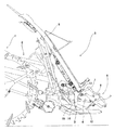
以下、本発明の実施の形態を図面に基づいて説明する。図1に示すように、移植機である乗用型田植機1の機体後部には、リンク機構2を介して植付部3を昇降自在に連結している。そして、植付部3には、図示しないシャフトケースを介して機体の左右方向に所定の間隔を存して複数の植付伝動ケース4を並設すると共に、該植付伝動ケース4の上方に左右往復動する前傾姿勢の苗載台5を取り付けてある。
Hereinafter, embodiments of the present invention will be described with reference to the drawings. As shown in FIG. 1, a planting part 3 is connected to a rear part of a riding type rice transplanter 1 as a transplanter via a link mechanism 2 so as to be movable up and down. The planting part 3 is provided with a plurality of
また、植付伝動ケース4後部の一側または両側には、乗用型田植機1の機体側から伝動される植付動力によって回転するロータリケース6と、その両端部に設けられる一対のプランタアーム7とを備える植付機構8が設けられると共に、植付伝動ケース4の下方には、上下揺動可能なフロート9を備えている。
Further, on one side or both sides of the rear portion of the
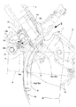
そして、プランタアーム7の先端部に備える植付爪10が所定の植付軌跡を描くように、ロータリケース6には図示しないギヤ列が内装されており、当該ロータリーケース6が回転すると、植付爪10が苗載台5の下端部から苗を掻取った後、前方に膨らむ円弧を描きながら土中の植付位置に達し、その後、直線的に上昇する半月状の静止軌跡A(図2に示す走行停止時の植付爪10の先端運動軌跡)を描くように構成されている。これにより、ロータリケース6が一回転する毎に二回の植付けが実行されるようになっている。
The
また、図2及び図3に示すように、左右往復動する苗載台5の下端部裏面側に側面視で略L字状の支持部材11を一体的に取着し、この支持部材11に下方に向け断面を略凹状に形成した複数個の樹脂製スライドピース12を螺設すると共に、該スライドピース12の凹状部に嵌装する断面が略角パイプ状の摺動レール部13aと、この摺動レール部13aから後方に一体延設した苗受け部13bとを有するエプロン13を機体の左右方向(幅方向)に配設して、当該苗載台5を左右往復動自在に支持している。
Further, as shown in FIGS. 2 and 3, a substantially L-
そして、前記苗受け部13bにより苗載台5上に載置したマット苗を受け止めると共に、植付爪10に対応するマット苗の掻き取り口13cが苗受け部13bに切欠き状に設けてあって、植付爪10が上述した静止軌跡Aに沿って掻き取り口13cの上から下へ通り抜けながら所定量のマット苗を掻き取ることができるようになっている。更に、エプロン13を苗載台5の傾斜方向に上下平行移動可能に構成してあり、前記苗受け部13bと植付爪10の静止軌跡Aとの相対的な位置関係を変更して、植付爪10によるマット苗の掻き取り量、即ち苗の植え付け本数を調節することができるようになっている。
The mat seedling placed on the
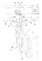
また、エプロン13の掻き取り口13cの下方には、この掻き取り口13cから植付爪10によって掻き取った苗の前方への倒れを抑制する第一苗ガイド14と、植付爪10によって掻き取った苗の拡散を抑制する第二苗ガイド15とを備えており、詳述すると、前記第一苗ガイド14は、針金状のステンレス材で形成されると共に、植付爪10によって掻き取った苗の前部に当接して植付爪10の静止軌跡Aに沿って撓み変形しながら、当該掻き取り苗の前方への倒れを抑制している。一方、樹脂製の第二苗ガイド15は、植付爪10によって掻き取った苗の拡散を抑制するための左右の側壁15a,15bを有し、両苗ガイド14,15によって適正な姿勢で苗の植付けが実行されるようになっている。
Further, below the scraping opening 13 c of the
更に、第二苗ガイド15の上部は、エプロン13の掻き取り口13cに嵌め込んだ状態で位置決めできるように門型状に形成されると共に、その下方に向けて左右の側壁15a,15bを一体延設している。そして、門型状に形成された第二苗ガイド15の上部後側には、当該第二苗ガイド15をエプロン13の苗受け部13bの下方側から螺設することができるように、側面視で略L字フランジ状の左右の取り付け部15c,15dを一体形成している。
Further, the upper part of the
また、上述の如く門型状に形成した第二苗ガイド15の前側上端部15eを、エプロン13の摺動レール部13aの下端部から斜め上方に延設すると共に、当該前側上端部15eに第一苗ガイド14の基端部14aを弾装するための嵌合部Fを設けている。更に詳しくは、針金状の第一苗ガイド14の基端部14aをリング状に曲げ加工すると共に、前記第二苗ガイド15に設けた嵌合部Fに対して第一苗ガイド14の基端部14aを、第二苗ガイド15を構成する樹脂の弾性を利用して把持できるように両者14a,Fの間の嵌合寸法を設定し、更に第一苗ガイド14の基端部14aを第二苗ガイド15の嵌合部Fに弾持した状態でボルト16、及びナット17を介して螺着できるように構成してある。
Further, the front
即ち、第一苗ガイド14の基端部14aを第二苗ガイド15に設けた嵌合部Fに弾持することにより、左右の側壁15a,15bを有す第二苗ガイド15に対する針金状の第一苗ガイド14の位置決めが容易になされると共に、次いで前記ボルト16、ナット17により螺着する際の第二苗ガイドに対する第一苗ガイドのズレが抑制されると共に、組立誤差等によって生じる植付爪10の描く植付軌跡Aに対する第一苗ガイド14の相対的な位置関係のズレを、第二苗ガイド15に取り付けた後の第一苗ガイド14単独で図中E矢印方向に調節することも可能である。更に、本実施例の如く第一苗ガイド14が針金状のガイドである場合は、二股状に切欠形成されている植付爪10の先端部中央に貫入した状態で作用するものであるから、当該第一苗ガイド14を植付爪10の先端部中央に位置合わせすることが容易に行えるので極めて有効である。
That is, by holding the
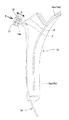
そして、上述したように、第一苗ガイド14の基端部14aを、第二苗ガイド15に設けた嵌合部Fに弾持した状態で螺着することができるので、組立作業性が大幅に向上する。また、図4に示すように、前記両苗ガイド14,15を一体的に組立てた状態でエプロン13に着脱することもでき、その場合は両苗ガイド14,15を個々に位置決めして取り付ける必要がないので作業時間の短縮化が図れると共に、両苗ガイド14,15を構成する部品の工程管理をより簡略化することができるようになる。
And as above-mentioned, since the
また、上述したように、第二苗ガイド15の前側上端部15eを、エプロン13の摺動レール部13aの下端部から斜め上方に延設すると共に、当該前側上端部15eに第一苗ガイド14の基端部14aを弾持するための嵌合部Fを設けているが、更に詳しくは、前記嵌合部Fは、図3及び図4に示す如く、エプロン13の掻取口13c上部の前方延長線C(門型状に形成された第二苗ガイド15の上部内面に相当)よりも上方に設けられているので、第一苗ガイド14の基端部14aを植付爪10の描く植付軌跡Aよりも離間させて取り付けることができ、しかもその取り付け部(嵌合部F)は第二苗ガイド15の前側上端部の前方に延設され、下方に向けて突出していないので、植付爪10によって掻き取られた苗の根や土が前記延設部の周辺に付着し難く、且つ泥落ちも良好となるので苗の植付姿勢に乱れが起こり難い。
Further, as described above, the front
尚、第二苗ガイド15の突起部15eの先端には、図4に示すD矢印方向からのボルト16の着脱を容易化するU字状の切欠きK(図3参照)を設けている。また、万一ナット17が脱落したとしても、リング状に曲げ加工された第一苗ガイド14の基端部14aに差し込まれたボルト16によって、当該第一苗ガイド14が容易に圃場に落下することはない。
A U-shaped notch K (see FIG. 3) is provided at the tip of the projecting
また、エプロン13を苗載台5の傾斜方向に上下平行移動することで、当該エプロン13の苗受け部13bと植付爪10との相対的な位置関係を変更し、それによって植付爪10によるマット苗の掻き取り量、即ち苗の植え付け本数を調節できるように構成してあるが、その際、エプロン13に一体的に組付けられている第一苗ガイド14と第二苗ガイド15は、当該エプロン13と共に平行移動するので、前記マット苗の掻き取り量の変更に伴って、針金状の第一苗ガイド14と植付爪10の描く植付軌跡(静止軌跡A)との大きなズレは起こらない。
Moreover, the relative positional relationship between the
5 苗載台
10 植付爪
13 エプロン
13a 摺動レール部
13b 苗受け部
13c 掻き取り口
14 第一苗ガイド
14a 基端部
15 第二苗ガイド
15e 前側上端部
F 嵌合部
5 Seedling stand 10
Claims (2)
Priority Applications (1)
| Application Number | Priority Date | Filing Date | Title |
|---|---|---|---|
| JP2004116920A JP4276575B2 (en) | 2004-04-12 | 2004-04-12 | Transplanter |
Applications Claiming Priority (1)
| Application Number | Priority Date | Filing Date | Title |
|---|---|---|---|
| JP2004116920A JP4276575B2 (en) | 2004-04-12 | 2004-04-12 | Transplanter |
Publications (3)
| Publication Number | Publication Date |
|---|---|
| JP2005295891A true JP2005295891A (en) | 2005-10-27 |
| JP2005295891A5 JP2005295891A5 (en) | 2007-04-19 |
| JP4276575B2 JP4276575B2 (en) | 2009-06-10 |
Family
ID=35328187
Family Applications (1)
| Application Number | Title | Priority Date | Filing Date |
|---|---|---|---|
| JP2004116920A Expired - Fee Related JP4276575B2 (en) | 2004-04-12 | 2004-04-12 | Transplanter |
Country Status (1)
| Country | Link |
|---|---|
| JP (1) | JP4276575B2 (en) |
Cited By (1)
| Publication number | Priority date | Publication date | Assignee | Title |
|---|---|---|---|---|
| JP2007236357A (en) * | 2006-03-13 | 2007-09-20 | Kubota Corp | Seedling guide structure of seedling planting equipment |
-
2004
- 2004-04-12 JP JP2004116920A patent/JP4276575B2/en not_active Expired - Fee Related
Cited By (1)
| Publication number | Priority date | Publication date | Assignee | Title |
|---|---|---|---|---|
| JP2007236357A (en) * | 2006-03-13 | 2007-09-20 | Kubota Corp | Seedling guide structure of seedling planting equipment |
Also Published As
| Publication number | Publication date |
|---|---|
| JP4276575B2 (en) | 2009-06-10 |
Similar Documents
| Publication | Publication Date | Title |
|---|---|---|
| TW201016126A (en) | Rice Transplanter | |
| JP4276575B2 (en) | Transplanter | |
| JP2003199408A (en) | Seedling transplanter | |
| JP6292170B2 (en) | Transplanter | |
| JP2009261278A (en) | Seedling transplanter | |
| JP4635723B2 (en) | Seedling transplanter | |
| CN205305392U (en) | Transplanting machine | |
| JP2016214115A5 (en) | ||
| JP2006333722A5 (en) | ||
| JP2011160670A (en) | Planting implement | |
| JP2012060891A (en) | Angle adjustment structure of shooter in transplanter | |
| JP5527193B2 (en) | Transplanter | |
| JP2004298201A (en) | Transplanter seedling removal device | |
| JP3454703B2 (en) | Transplant machine | |
| JP2011193745A (en) | Transplanter | |
| JP2007053984A (en) | Seedling transplanter of seedling transplanter | |
| JPS6222094Y2 (en) | ||
| JP2009082094A (en) | Seedling transplanter | |
| JP3183612B2 (en) | Transplanter seedling frame vertical feeder | |
| JPH09103157A (en) | Seedling push-out fork in transplanter | |
| JP5679379B1 (en) | Transplanter | |
| JP4864467B2 (en) | Transplanter | |
| JPH07132007A (en) | Seedling chuter structure of planting part in transplanter | |
| JPS592616A (en) | Seedling transplanter | |
| JP5418462B2 (en) | Transplanter |
Legal Events
| Date | Code | Title | Description |
|---|---|---|---|
| A521 | Written amendment |
Effective date: 20070226 Free format text: JAPANESE INTERMEDIATE CODE: A523 |
|
| A621 | Written request for application examination |
Free format text: JAPANESE INTERMEDIATE CODE: A621 Effective date: 20070228 |
|
| A977 | Report on retrieval |
Effective date: 20090109 Free format text: JAPANESE INTERMEDIATE CODE: A971007 |
|
| TRDD | Decision of grant or rejection written | ||
| A01 | Written decision to grant a patent or to grant a registration (utility model) |
Effective date: 20090224 Free format text: JAPANESE INTERMEDIATE CODE: A01 |
|
| A01 | Written decision to grant a patent or to grant a registration (utility model) |
Free format text: JAPANESE INTERMEDIATE CODE: A01 |
|
| A61 | First payment of annual fees (during grant procedure) |
Free format text: JAPANESE INTERMEDIATE CODE: A61 Effective date: 20090306 |
|
| FPAY | Renewal fee payment (prs date is renewal date of database) |
Year of fee payment: 3 Free format text: PAYMENT UNTIL: 20120313 |
|
| LAPS | Cancellation because of no payment of annual fees |