JP2005295798A - Power supply device for potable equipment - Google Patents
Power supply device for potable equipment Download PDFInfo
- Publication number
- JP2005295798A JP2005295798A JP2005159580A JP2005159580A JP2005295798A JP 2005295798 A JP2005295798 A JP 2005295798A JP 2005159580 A JP2005159580 A JP 2005159580A JP 2005159580 A JP2005159580 A JP 2005159580A JP 2005295798 A JP2005295798 A JP 2005295798A
- Authority
- JP
- Japan
- Prior art keywords
- adapter
- battery
- input terminal
- power
- voltage
- Prior art date
- Legal status (The legal status is an assumption and is not a legal conclusion. Google has not performed a legal analysis and makes no representation as to the accuracy of the status listed.)
- Granted
Links
- 238000001514 detection method Methods 0.000 claims description 6
- 238000010586 diagram Methods 0.000 description 3
- 239000004973 liquid crystal related substance Substances 0.000 description 1
Images


Landscapes
- Charge And Discharge Circuits For Batteries Or The Like (AREA)
Abstract
Description
本発明はデジタルカメラ、テープレコーダ、ノートパソコン等の携帯型機器の電源装置に係り、特に電池を電源とする携帯型機器の電源装置に関する。 The present invention relates to a power supply device for a portable device such as a digital camera, a tape recorder, or a notebook computer, and more particularly to a power supply device for a portable device that uses a battery as a power source.
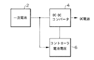
一般に、この種の携帯型機器の電源装置は、図8に示すようにアルカリ乾電池等の一次電池2から電源がDC−DCコンバータ4及びコントローラ6に供給され、DC−DCコンバータ4及びコントローラ6が動作する。DC−DCコンバータ4は、入力電圧を携帯型機器内の各回路の動作に必要な各種の電圧に変換して出力する。コントローラ6は、一次電池2の残量(電圧)を検知し、残量がなくなれば、DC−DCコンバータ4の動作を停止させ、また必要に応じて電池切れを示す表示等を行わせるようにしている。
Generally, in this type of portable device power supply, power is supplied from a
しかし、機器の消費電力が大きくなり、しかも機器の小型化を実現するためには、機器の電源として機器内部に二次電池を使用し、二次電池の残量がないときに、ACアダプタを機器の電源入力端子に接続し、この電源入力端子を介して機器に電源を供給し、二次電池の充電等を行うようにしている。また、屋外等でACアダプタを使用することができない場合には、一次電池が収納される電池アダプタを機器に取り付け、一時的に機器に電源を供給するようにしている。 However, in order to increase the power consumption of the device and to reduce the size of the device, a secondary battery is used as the power source of the device, and the AC adapter is used when there is no remaining battery. The device is connected to the power input terminal of the device, and power is supplied to the device through the power input terminal to charge the secondary battery. When the AC adapter cannot be used outdoors or the like, a battery adapter that stores a primary battery is attached to the device, and power is temporarily supplied to the device.
しかしながら、電池アダプタを機器に取り付け、この電池アダプタからの電源を機器に供給する場合には、ACアダプタが接続される電源入力端子とは別の電源入力端子を機器に設ける必要があり、機器の電源入力端子の数が多くなる等の問題がある。 However, when the battery adapter is attached to the device and the power from the battery adapter is supplied to the device, it is necessary to provide the device with a power input terminal different from the power input terminal to which the AC adapter is connected. There are problems such as an increase in the number of power input terminals.
一方、電池アダプタをACアダプタが接続される電源入力端子に接続できるようにする構成が考えられるが、この場合には、電池アダプタの一次電池によって機器内の二次電池を充電することになり、電池アダプタの一次電池の利用効率が悪いという問題がある。 On the other hand, it is possible to connect the battery adapter to the power input terminal to which the AC adapter is connected. In this case, the secondary battery in the device is charged by the primary battery of the battery adapter. There exists a problem that the utilization efficiency of the primary battery of a battery adapter is bad.
本発明はこのような事情に鑑みてなされたもので、電源入力端子の数を増やすことなく電池アダプタの一次電池を有効に利用することができる携帯型機器の電源装置を提供することを目的とする。 The present invention has been made in view of such circumstances, and an object thereof is to provide a power supply device for a portable device that can effectively use a primary battery of a battery adapter without increasing the number of power input terminals. To do.
前記目的を達成するために請求項1に係る発明は、二次電池から電源が供給されるとともに、外部のACアダプタが接続される電源入力端子を介して電源が供給される携帯型機器の電源装置において、前記電源入力端子に接続され、該電源入力端子を介して電源の供給が可能な電池アダプタと、前記電源入力端子に前記ACアダプタ及び電池アダプタのうちのいずれが接続されたかを識別する識別手段と、前記電源入力端子を介して供給される電源を負荷に供給し、該電源入力端子における端子電圧の変動幅を示すドロップ電圧を検出する検出手段と、を備え、前記識別手段は、前記検出手段によって検出されるドロップ電圧の大きさに基づいて前記ACアダプタ及び電池アダプタのうちのいずれが接続されたかを識別することを特徴としている。即ち、ACアダプタと電池アダプタが接続される電源入力端子を共用し、この電源入力端子における端子電圧の変動幅を示すドロップ電圧を検出することによって、電源入力端子にACアダプタが接続されているか、電池アダプタが接続されているかを識別するようにしている。 In order to achieve the above object, the invention according to claim 1 provides a power source for a portable device to which power is supplied from a secondary battery and to which power is supplied via a power input terminal to which an external AC adapter is connected. In the apparatus, a battery adapter connected to the power input terminal and capable of supplying power via the power input terminal and which of the AC adapter and the battery adapter is connected to the power input terminal are identified. Identification means; and detection means for supplying a power supplied via the power input terminal to a load and detecting a drop voltage indicating a fluctuation range of the terminal voltage at the power input terminal. It is characterized by identifying which one of the AC adapter and the battery adapter is connected based on the magnitude of the drop voltage detected by the detecting means. That. That is, by sharing the power input terminal to which the AC adapter and the battery adapter are connected, and detecting the drop voltage indicating the fluctuation range of the terminal voltage at the power input terminal, whether the AC adapter is connected to the power input terminal, The battery adapter is identified.
請求項2に示すように請求項1に記載の携帯型機器の電源装置において、前記電源入力端子を介して供給される電源によって前記二次電池を充電する充電手段であって、前記識別手段によって電池アダプタが接続されていると識別されると、前記二次電池への充電を禁止する充電手段を備えたことを特徴としている。即ち、前記電源入力端子に電池アダプタが接続された場合には、機器内の二次電池の充電を禁止し、機器に対してのみ電源を供給し、これにより電池アダプタ内に収納される電池(一次電池)を効率よく利用できるようにしている。 The portable device power supply device according to claim 1, wherein the secondary battery is charged by the power supplied via the power input terminal, and the identification device When it is identified that a battery adapter is connected, the battery pack is provided with charging means for prohibiting charging of the secondary battery. That is, when a battery adapter is connected to the power input terminal, charging of the secondary battery in the device is prohibited, power is supplied only to the device, and thereby the battery ( Primary battery) can be used efficiently.
請求項3に示すように請求項1に記載の携帯型機器の電源装置において、前記電源入力端子を介して供給される電源によって前記二次電池を充電する充電手段と、前記二次電池の電圧を検出する電圧検出手段と、前記識別手段によってACアダプタが接続されていると識別され、かつ前記電圧検出手段によって検出される電圧に基づいて前記二次電池が満充電されていないと判別すると、前記充電手段による前記二次電池の充電を行わせる充電制御手段と、を備えたことを特徴としている。 The power supply device for a portable device according to claim 1, wherein charging means for charging the secondary battery with a power supplied via the power input terminal, and a voltage of the secondary battery. When it is determined that the secondary battery is not fully charged based on the voltage detected by the voltage detection means and the identification means that the AC adapter is connected, and the voltage detected by the voltage detection means, Charging control means for charging the secondary battery by the charging means.
請求項4に示すように請求項1乃至3のいずれかに記載の携帯型機器の電源装置において、前記負荷は前記二次電池の充電に伴う負荷であることを特徴としている。 According to a fourth aspect of the present invention, in the portable device power supply device according to any one of the first to third aspects, the load is a load accompanying charging of the secondary battery.
本発明によれば、単一の電源入力端子をACアダプタ及び電池アダプタに共用することができ、これにより端子構成を簡略化することができ、また、この電源入力端子における端子電圧の変動幅を示すドロップ電圧を検出することにより、電源入力端子にACアダプタが接続されているか電池アダプタが接続されているかを識別することができる。そして、電源入力端子に電池アダプタが接続されたことが識別された場合には、電池アダプタの電池による携帯型機器内の二次電池への充電を禁止するようにしたため、電池アダプタ内の電池を効率よく利用することができる。 According to the present invention, it is possible to share a single power input terminal for the AC adapter and the battery adapter, thereby simplifying the terminal configuration and reducing the fluctuation range of the terminal voltage at the power input terminal. By detecting the indicated drop voltage, it is possible to identify whether an AC adapter or a battery adapter is connected to the power input terminal. When it is identified that the battery adapter is connected to the power input terminal, charging of the secondary battery in the portable device by the battery of the battery adapter is prohibited. It can be used efficiently.
以下添付図面に従って本発明に係る以下添付図面に従って本発明に係る携帯型機器の電源装置の好ましい実施の形態について詳説する。 DETAILED DESCRIPTION OF THE PREFERRED EMBODIMENTS Preferred embodiments of a power supply device for portable equipment according to the present invention will be described in detail with reference to the accompanying drawings.
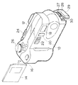
図1は本発明に係る携帯型機器の電源装置が適用されたデジタルカメラを示す斜視図である。 FIG. 1 is a perspective view showing a digital camera to which a power supply device for a portable device according to the present invention is applied.
同図に示すように、このデジタルカメラのフロントキャビ10、リアキャビ12は、図1上で右側部にレンズ/ファインダユニットが収納できるように形成されており、フロントキャビ10、リアキャビ12の左側部は、グリップ部が形成されるとともに、メモリカード(スマートメディア)14が着脱可能に形成されている。また、フロントキャビ10には、レリーズボタン16、ファインダ窓18、調光センサやセルフLED用の窓20、ストロボカバー22等が配設され、リアキャビ12にはパワースイッチ24、モードダイヤル26、液晶モニタ28等が配設されている。
As shown in the figure, the
デジタルカメラの右側面の下部には、RS232Cのシリアル端子27、ビデオ出力端子28、電源(DC)入力端子30等が配設されている。尚、29は、端子カバーである。また、このデジタルカメラ内には、図示しない二次電池が収納されている。
Below the right side of the digital camera, an RS232C
このデジタルカメラには、図示しない二次電池が収納されており、また、電池アダプタがオプション又は付属品として用意されている。電池アダプタは、例えば複数本の一次電池が収納できるように構成されるとともに、DC入力端子30に接続するためのプラグ付きの接続コードを有しており、三脚穴等を使用してカメラ底部に取り付けられる。
In this digital camera, a secondary battery (not shown) is accommodated, and a battery adapter is prepared as an option or an accessory. The battery adapter is configured to accommodate, for example, a plurality of primary batteries, and has a connection cord with a plug for connecting to the
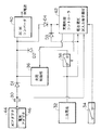
図2はこのデジタルカメラの電源装置の実施の形態を示すブロック図である。である。 FIG. 2 is a block diagram showing an embodiment of the power supply device of the digital camera. It is.
同図に示すように、この電源装置は、種としてDC入力端子30と、二次電池32と、電池アダプタ識別スイッチ34と、充電制御部36と、放電スイッチ38と、DC−DCコンバータ40と、コントローラ42とから構成されている。
As shown in the figure, the power supply device includes, as seeds, a
DC入力端子30には、外部のACアダプタ44又は電池アダプタ46のプラグを差し込むことができるようになっており、DC入力端子30を介して入力する電源は、ダイオードD1を介してDC−DCコンバータ40に加えられるとともに、ダイオードD1、D4を介してコントローラ42に加えられる。
An
一方、二次電池32の電源は、放電スイッチ38及びダイオードD2を介してDC−DCコンバータ40に加えられるとともに、ダイオードD3を介してコントローラ42に加えられる。更に、DC入力端子30を介して入力する電源、及び二次電池32の電源は、その電圧が検出できるようにダイレクトにコントローラ42に加えられるようになっている。
On the other hand, the power source of the
コントローラ42は、二次電池32の電池電圧を検出することにより残量を判断し、残量があると判断したときには放電スイッチ38をONにし、二次電池32の電源を放電スイッチ38及びダイオードD2を介してDC−DCコンバータ40に供給する。
The
また、コントローラ42は、DC入力端子30にACアダプタ44又は電池アダプタ46が接続されたことを検出するとともに、電池アダプタ識別スイッチ34からの検出信号に基づいてACアダプタ44及び電池アダプタ46のうちの何れが接続されたかを判断している。そして、DC入力端子30にACアダプタ44が接続されていると判断し、二次電池32の電池電圧から満充電でないと判断したときには、充電制御部36を制御し、二次電池32を充電する。
Further, the
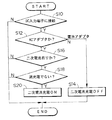
次に、上記構成の電源装置の動作を、図3のフローチャート及び図4のグラフを参照しながら説明する。 Next, the operation of the power supply apparatus having the above configuration will be described with reference to the flowchart of FIG. 3 and the graph of FIG.
まず、図3のステップS10において、DC入力端子30にACアダプタ44又は電池アダプタ46が接続されているか否かを判断する。この判断は、DC入力端子電圧が、図4に示す判断電圧V3以上か否かによって行う。DC入力端子30にACアダプタ44又は電池アダプタ46が接続されていることが判別されると、ACアダプタ44及び電池アダプタ46のうちの何れが接続されているかを判断する(ステップS12)。この判断は、前述したように電池アダプタ識別スイッチ34からの検出信号に基づいて行う。尚、電池アダプタ識別スイッチ34は、電池アダプタ46の機器(デジタルカメラ)への着脱に連動してON/OFFするスイッチである。
First, in step S10 of FIG. 3, it is determined whether or not the
ステップS12において、電池アダプタ46が接続されていることが判別されると、二次電池32の充電をOFFする(ステップS14)。
If it is determined in step S12 that the
一方、ステップS12において、ACアダプタ44が接続されていることが判別されると、続いて二次電池32の有無が判断される(ステップS16)。この判断は、電池電圧が図4に示す判断電圧V4以上か否かによって行う。そして、二次電池32が装填されていると判断した場合には、その二次電池32が満充電されているか否かを判断する(ステップS18)。この判断は、電池電圧が図4に示す判断電圧V5以上か否かによって行う。
On the other hand, if it is determined in step S12 that the
ステップS18において、二次電池32が満充電されていないと判別した場合には、充電制御部36を制御し、二次電池32の充電を行わせる(ステップS20)。
If it is determined in step S18 that the
一方、ステップS16において、二次電池32が装填されていないと判断した場合、及びステップS18において、二次電池32が満充電されていると判断した場合には、二次電池32の充電制御は行わない。
On the other hand, if it is determined in step S16 that the
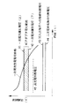
図4のグラフは、上記判断電圧の他に電池アダプタ46の収納される一次電池の放電電圧曲線及びACアダプタ44の電圧範囲を示している。
The graph of FIG. 4 shows the discharge voltage curve of the primary battery accommodated in the
現在、電池アダプタ46のプラグがDC入力端子30に差し込まれているが、電池アダプタ46が正常に装着されていない場合には、電池アダプタ識別スイッチ34が有効に動作しない可能性があり、この場合には、コントローラ42はACアダプタ44が装着されていると誤検出する。
At present, the plug of the
そこで、コントローラ42は、電池アダプタ識別スイッチ34によって電池アダプタ46が接続されていない(即ち、ACアダプタ44が接続されている)と判断した場合には、DC入力端子電圧が、図4に示すACアダプタ44の電圧範囲(V1〜V2)か否かを判断する。そして、DC入力端子電圧が、ACアダプタ44の電圧範囲外の場合には、電池アダプタ46が接続されているものと判断し、電池アダプタ46の電源による二次電池32の充電を禁止する。
Therefore, when the
尚、図4では、一次電池の放電電圧曲線とACアダプタの電圧範囲とが一部重なる場合があるが、図5に示すように一次電池の放電電圧曲線とACアダプタの電圧範囲とが重ならないように一次電池の放電電圧曲線及びACアダプタの電圧範囲を設定することも可能である。そして、この場合には、電池アダプタ識別スイッチ34を設けることなく、DC入力端子電圧が、図5に示す判断電圧V6以上か否かによってACアダプタが接続されているか、電池アダプタが接続されているかを判断することができる。
In FIG. 4, the discharge voltage curve of the primary battery and the voltage range of the AC adapter may partially overlap, but the discharge voltage curve of the primary battery and the voltage range of the AC adapter do not overlap as shown in FIG. Thus, it is also possible to set the discharge voltage curve of the primary battery and the voltage range of the AC adapter. In this case, without providing the battery
次に、DC入力端子にACアダプタ及び電池アダプタのうちの何れが接続されているかを識別する識別手段の他の実施の形態について説明する。 Next, another embodiment of identification means for identifying which of the AC adapter and the battery adapter is connected to the DC input terminal will be described.
図6に示すように、所定の時刻t1にDC入力端子30から入力する電源に負荷を与え、DC入力端子30における端子電圧のドロップ電圧(−ΔV1,−ΔV2)を検出する。電池アダプタ46からの電源に負荷を与えた場合のドロップ電圧の絶対値|−ΔV1|は、ACアダプタ44からの電源に負荷を与えた場合のドロップ電圧の絶対値|−ΔV2|よりも大きい(|−ΔV1|>|−ΔV2|)。
As shown in FIG. 6, a load is applied to the power supply input from the
従って、ドロップ電圧(|−ΔV1|)と(|−ΔV2|)との中間の電圧値を識別係数kとして設定すると、検出したドロップ電圧(|−ΔV|)が識別係数kよりも小さい場合(|−ΔV|<k)には、ACアダプタ44が接続されていると判別することができ、検出したドロップ電圧(|−ΔV|)が識別係数kよりも大きい場合(|−ΔV|>k)には、電池アダプタ46が接続されていると判別することができる。
Accordingly, when an intermediate voltage value between the drop voltages (| −ΔV1 |) and (| −ΔV2 |) is set as the identification coefficient k, the detected drop voltage (| −ΔV |) is smaller than the identification coefficient k ( When | −ΔV | <k), it can be determined that the
図7は本発明に係る電源装置の動作の他の実施の形態を示すフローチャートである。 FIG. 7 is a flowchart showing another embodiment of the operation of the power supply device according to the present invention.
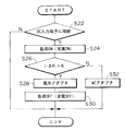
同図に示すように、まずDC入力端子30にACアダプタ44又は電池アダプタ46が接続されているか否かを判断する(ステップS22)。DC入力端子30にACアダプタ44又は電池アダプタ46が接続されていることが判別されると、DC入力端子30から入力する電源に負荷を与える。この実施の形態では、二次電池32の充電を実施する(ステップS24)。
As shown in the figure, it is first determined whether or not the
続いて、上記負荷を与えたときのDC入力端子30のドロップ電圧(|−ΔV|)を検出し、この検出したドロップ電圧(|−ΔV|)と、前述した識別係数kとを比較する(ステップS26)。
Subsequently, the drop voltage (| −ΔV |) of the
そして、ドロップ電圧(|−ΔV|)が識別係数kよりも大きい場合(|−ΔV|>k)には、電池アダプタ46が接続されていると判別し(ステップS28)、負荷をOFF(充電をOFF)にする(ステップS30)。
When the drop voltage (| −ΔV |) is larger than the identification coefficient k (| −ΔV |> k), it is determined that the
一方、ドロップ電圧(|−ΔV|)が識別係数kよりも小さい場合(|−ΔV|<k)には、ACアダプタ44が接続されていると判別し(ステップS32)二次電池32の充電制御を引き続き行う。
On the other hand, when the drop voltage (| −ΔV |) is smaller than the identification coefficient k (| −ΔV | <k), it is determined that the
尚、本発明に係る電源装置は、この実施の形態のデジタルカメラに限らず、他の携帯型機器に適用できる。 The power supply device according to the present invention is not limited to the digital camera of this embodiment, and can be applied to other portable devices.
30…電源(DC)入力端子、32…二次電圧、34…電池アダプタ識別スイッチ、36…充電制御部、38…放電スイッチ、40…DC−DCコンバータ、42…コントローラ、44…ACアダプタ、46…電池アダプタ
DESCRIPTION OF
Claims (4)
前記電源入力端子に接続され、該電源入力端子を介して電源の供給が可能な電池アダプタと、
前記電源入力端子に前記ACアダプタ及び電池アダプタのうちのいずれが接続されたかを識別する識別手段と、
前記電源入力端子を介して供給される電源を負荷に供給し、該電源入力端子における端子電圧の変動幅を示すドロップ電圧を検出する検出手段と、を備え、
前記識別手段は、前記検出手段によって検出されるドロップ電圧の大きさに基づいて前記ACアダプタ及び電池アダプタのうちのいずれが接続されたかを識別することを特徴とする携帯型機器の電源装置。 In a power supply device for a portable device in which power is supplied from a secondary battery and power is supplied through a power input terminal to which an external AC adapter is connected.
A battery adapter connected to the power input terminal and capable of supplying power via the power input terminal;
Identifying means for identifying which of the AC adapter and the battery adapter is connected to the power input terminal;
Detecting means for supplying a power supplied via the power input terminal to a load and detecting a drop voltage indicating a fluctuation range of the terminal voltage at the power input terminal;
The power supply apparatus for a portable device, wherein the identification unit identifies which of the AC adapter and the battery adapter is connected based on a magnitude of a drop voltage detected by the detection unit.
Priority Applications (1)
| Application Number | Priority Date | Filing Date | Title |
|---|---|---|---|
| JP2005159580A JP3849141B2 (en) | 2005-05-31 | 2005-05-31 | Power supply for portable equipment |
Applications Claiming Priority (1)
| Application Number | Priority Date | Filing Date | Title |
|---|---|---|---|
| JP2005159580A JP3849141B2 (en) | 2005-05-31 | 2005-05-31 | Power supply for portable equipment |
Related Parent Applications (1)
| Application Number | Title | Priority Date | Filing Date |
|---|---|---|---|
| JP27125597A Division JP3797514B2 (en) | 1997-10-03 | 1997-10-03 | Digital camera power supply |
Publications (2)
| Publication Number | Publication Date |
|---|---|
| JP2005295798A true JP2005295798A (en) | 2005-10-20 |
| JP3849141B2 JP3849141B2 (en) | 2006-11-22 |
Family
ID=35328098
Family Applications (1)
| Application Number | Title | Priority Date | Filing Date |
|---|---|---|---|
| JP2005159580A Expired - Fee Related JP3849141B2 (en) | 2005-05-31 | 2005-05-31 | Power supply for portable equipment |
Country Status (1)
| Country | Link |
|---|---|
| JP (1) | JP3849141B2 (en) |
Cited By (1)
| Publication number | Priority date | Publication date | Assignee | Title |
|---|---|---|---|---|
| EP2528190A3 (en) * | 2011-04-08 | 2015-02-25 | Fujitsu Limited | Ac adapter and electronic apparatus unit |
-
2005
- 2005-05-31 JP JP2005159580A patent/JP3849141B2/en not_active Expired - Fee Related
Cited By (2)
| Publication number | Priority date | Publication date | Assignee | Title |
|---|---|---|---|---|
| EP2528190A3 (en) * | 2011-04-08 | 2015-02-25 | Fujitsu Limited | Ac adapter and electronic apparatus unit |
| US9240734B2 (en) | 2011-04-08 | 2016-01-19 | Fujitsu Limited | AC adapter and electronic apparatus unit |
Also Published As
| Publication number | Publication date |
|---|---|
| JP3849141B2 (en) | 2006-11-22 |
Similar Documents
| Publication | Publication Date | Title |
|---|---|---|
| JP4664362B2 (en) | Electrical device, method for identifying host device, method for determining power availability of power supply, and method for managing power usage of electrical device | |
| US7839121B2 (en) | Apparatus and method for managing power of battery packs in a portable device | |
| US8159185B2 (en) | Battery charger and control method therefor | |
| TWI385889B (en) | Power system, power board and electronic equipment | |
| US9350182B2 (en) | Multi-port charging device | |
| JP2530098B2 (en) | Portable electronic device, its battery pack, its charger, and its attachment | |
| US20180048168A1 (en) | Multi-functional high capacity portable power charger | |
| EP0987620A2 (en) | Function extending apparatus, electronic apparatus and electronic system | |
| US20200106291A1 (en) | Electronic device and control method | |
| CN101043146B (en) | Apparatus and method for managing power of battery packs in a portable device | |
| US5784295A (en) | Method and apparatus for determining residual battery voltage | |
| US20030221134A1 (en) | Electronic equipment, display control method, recording medium and program | |
| JP7305427B2 (en) | Electronics | |
| JP3849141B2 (en) | Power supply for portable equipment | |
| US20060152192A1 (en) | Electronic device and adaptor used therewith | |
| JP2005253147A (en) | Portable imaging device and power supply switching control method | |
| JP3797514B2 (en) | Digital camera power supply | |
| US20180041700A1 (en) | Electronic device, method for controlling electronic device, and storage medium | |
| KR100788595B1 (en) | Portable auxiliary power supply | |
| JP2022047802A (en) | Electronic apparatus, battery pack, control method and program | |
| JP2005045894A (en) | Battery-driven electronic equipment | |
| US20060186858A1 (en) | Charging apparatus | |
| KR19990079134A (en) | Electronic device using a plurality of batteries and a method of controlling the power thereof | |
| US20110187195A1 (en) | Intelligent Low-Consumption Adaptor | |
| KR20040026379A (en) | Power supply for portable device |
Legal Events
| Date | Code | Title | Description |
|---|---|---|---|
| A131 | Notification of reasons for refusal |
Effective date: 20060510 Free format text: JAPANESE INTERMEDIATE CODE: A131 |
|
| A521 | Written amendment |
Free format text: JAPANESE INTERMEDIATE CODE: A523 Effective date: 20060707 |
|
| TRDD | Decision of grant or rejection written | ||
| A01 | Written decision to grant a patent or to grant a registration (utility model) |
Effective date: 20060807 Free format text: JAPANESE INTERMEDIATE CODE: A01 |
|
| A61 | First payment of annual fees (during grant procedure) |
Free format text: JAPANESE INTERMEDIATE CODE: A61 Effective date: 20060820 |
|
| R150 | Certificate of patent (=grant) or registration of utility model |
Free format text: JAPANESE INTERMEDIATE CODE: R150 |
|
| FPAY | Renewal fee payment (prs date is renewal date of database) |
Free format text: PAYMENT UNTIL: 20090908 Year of fee payment: 3 |
|
| S111 | Request for change of ownership or part of ownership |
Free format text: JAPANESE INTERMEDIATE CODE: R313111 |
|
| FPAY | Renewal fee payment (prs date is renewal date of database) |
Free format text: PAYMENT UNTIL: 20090908 Year of fee payment: 3 |
|
| R350 | Written notification of registration of transfer |
Free format text: JAPANESE INTERMEDIATE CODE: R350 |
|
| FPAY | Renewal fee payment (prs date is renewal date of database) |
Year of fee payment: 3 Free format text: PAYMENT UNTIL: 20090908 |
|
| FPAY | Renewal fee payment (prs date is renewal date of database) |
Free format text: PAYMENT UNTIL: 20100908 Year of fee payment: 4 |
|
| FPAY | Renewal fee payment (prs date is renewal date of database) |
Free format text: PAYMENT UNTIL: 20100908 Year of fee payment: 4 |
|
| FPAY | Renewal fee payment (prs date is renewal date of database) |
Year of fee payment: 5 Free format text: PAYMENT UNTIL: 20110908 |
|
| FPAY | Renewal fee payment (prs date is renewal date of database) |
Free format text: PAYMENT UNTIL: 20120908 Year of fee payment: 6 |
|
| FPAY | Renewal fee payment (prs date is renewal date of database) |
Free format text: PAYMENT UNTIL: 20130908 Year of fee payment: 7 |
|
| LAPS | Cancellation because of no payment of annual fees |