JP2005295770A - Power converting device and method of setting overheat protection temperature to power converting device - Google Patents
Power converting device and method of setting overheat protection temperature to power converting device Download PDFInfo
- Publication number
- JP2005295770A JP2005295770A JP2004111316A JP2004111316A JP2005295770A JP 2005295770 A JP2005295770 A JP 2005295770A JP 2004111316 A JP2004111316 A JP 2004111316A JP 2004111316 A JP2004111316 A JP 2004111316A JP 2005295770 A JP2005295770 A JP 2005295770A
- Authority
- JP
- Japan
- Prior art keywords
- power conversion
- temperature
- power
- overheat protection
- temperature sensor
- Prior art date
- Legal status (The legal status is an assumption and is not a legal conclusion. Google has not performed a legal analysis and makes no representation as to the accuracy of the status listed.)
- Granted
Links
- 238000000034 method Methods 0.000 title claims description 20
- 238000006243 chemical reaction Methods 0.000 claims description 170
- 239000003507 refrigerant Substances 0.000 claims description 18
- 238000001816 cooling Methods 0.000 claims description 14
- 239000002826 coolant Substances 0.000 claims 1
- 230000001681 protective effect Effects 0.000 abstract 5
- 238000010586 diagram Methods 0.000 description 13
- 238000010248 power generation Methods 0.000 description 4
- 239000000446 fuel Substances 0.000 description 3
- 230000002159 abnormal effect Effects 0.000 description 1
- 239000000498 cooling water Substances 0.000 description 1
- 238000013461 design Methods 0.000 description 1
- 230000006866 deterioration Effects 0.000 description 1
- 238000011161 development Methods 0.000 description 1
- 230000000694 effects Effects 0.000 description 1
- 230000005669 field effect Effects 0.000 description 1
- 239000002803 fossil fuel Substances 0.000 description 1
- 238000012986 modification Methods 0.000 description 1
- 230000004048 modification Effects 0.000 description 1
- 238000013021 overheating Methods 0.000 description 1
Images

Landscapes
- Protection Of Static Devices (AREA)
- Power Conversion In General (AREA)
Abstract
Description
本発明は電力変換装置に関し、特に、複数の電力変換部を備える電力変換装置に関する。また、本発明は電力変換装置への過熱保護温度設定方法に関し、特に、複数の電力変換部を備える電力変換装置への過熱保護温度設定方法に関する。 The present invention relates to a power conversion device, and particularly to a power conversion device including a plurality of power conversion units. The present invention also relates to an overheat protection temperature setting method for a power converter, and more particularly, to an overheat protection temperature setting method for a power converter including a plurality of power converters.
近年、化石燃料の枯渇や地球環境の悪化を背景として、ハイブリッド車や燃料電池車のような、電気エネルギーを利用した自動車への関心が高まりをみせている。電気エネルギーを用いた自動車には、車輪を駆動するためのモータや、モータに電力を供給するための高圧バッテリーの他、高圧バッテリーの電圧を降圧する電力変換装置が備えられることが多い。すなわち、車輪を駆動するためのモータが必要とする電圧は約120〜400Vと比較的高い一方、自動車に備えられるエアコンやオーディオ等の電気機器が必要とする電圧は約12V程度であることから、高圧バッテリーの電圧は約120〜400Vに設定されるとともに、車輪を駆動するためのモータに対してはこれが直接供給され、エアコンやオーディオ等の電気機器に対しては電力変換装置によって降圧された電圧が供給される。 In recent years, with the background of depletion of fossil fuels and the deterioration of the global environment, interest in automobiles that use electric energy, such as hybrid cars and fuel cell cars, has increased. In many cases, an automobile using electric energy is equipped with a motor for driving wheels, a high-voltage battery for supplying electric power to the motor, and a power conversion device for stepping down the voltage of the high-voltage battery. That is, while the voltage required by the motor for driving the wheels is relatively high at about 120 to 400 V, the voltage required by electric equipment such as an air conditioner and audio provided in the automobile is about 12 V. The voltage of the high-voltage battery is set to about 120 to 400 V, and the voltage is directly supplied to the motor for driving the wheel, and the voltage is stepped down by the power converter for the electric equipment such as the air conditioner and the audio. Is supplied.
この種の電力変換装置は、その内部にスイッチング回路や整流回路等を有していることから、これらに含まれるFET(電界効果トランジスタ)やダイオードの発熱による破損防止を目的として、温度センサが設けられることが多い。このような温度センサによりあらかじめ定められた過熱保護温度に達したことが検出されると、電力変換装置に含まれる制御部は出力を停止若しくは制限し、これにより熱によるFETやダイオードの破損を未然に防止している(特許文献1参照)。
しかしながら、自動車に搭載される電気機器の数は年々増加しており、このため近年、電力変換装置にはより大きな出力が求められている。これを満たすためには、より高出力な電力変換装置を新たに設計し直すほか、既に設計されている低出力の電力変換部を並列運転させるという方法が考えられ、特に後者の方法によれば、開発コストを大幅に抑制することが可能となる。並列運転の例としては、例えば特許文献2に記載されている。
However, the number of electrical devices mounted on automobiles is increasing year by year, and therefore, in recent years, power converters are required to have a larger output. In order to satisfy this, in addition to redesigning a higher power converter, a method of operating a low-power converter already designed in parallel can be considered. Development costs can be significantly reduced. An example of parallel operation is described in
ところが、複数の電力変換部を並列に運転させると、ある電力変換部が発する熱が他の電力変換部内へと伝わるため、温度センサによる過熱保護動作が不正確になるという問題があった。例えば2台の電力変換部を並列に運転させた場合において、一方の電力変換部が他方の電力変換部の温度センサに与える熱の影響と、他方の電力変換部が一方の電力変換部の温度センサに与える熱の影響とが異なる場合、より熱の影響を受けにくい側の電力変換部が先に過熱保護動作(出力停止や出力制限)を行うと、もともと熱の影響を多く受けていた側の電力変換部はなかなか過熱保護動作に入らなくなり、その結果、FETやダイオードが損傷するという可能性があった。 However, when a plurality of power conversion units are operated in parallel, the heat generated by a certain power conversion unit is transferred to the other power conversion units, which causes a problem that the overheat protection operation by the temperature sensor becomes inaccurate. For example, when two power conversion units are operated in parallel, the influence of heat that one power conversion unit has on the temperature sensor of the other power conversion unit, and the temperature of the other power conversion unit is one of the power conversion units When the heat effect on the sensor is different, if the power converter on the side that is less susceptible to heat performs the overheat protection operation (output stop or output restriction) first, the side that was originally heavily affected by heat However, the power conversion unit of this type cannot easily enter the overheat protection operation, and as a result, there is a possibility that the FET and the diode are damaged.
したがって、本発明の目的は、複数の電力変換部を備える電力変換装置及びこのような電力変換装置への過熱保護温度設定方法であって、一部の電力変換部が過熱保護動作を行った場合であっても、他の電力変換部が正常に過熱保護動作を行うことが可能な電力変換装置及び過熱保護温度設定方法を提供することである。 Accordingly, an object of the present invention is a power conversion device including a plurality of power conversion units and an overheat protection temperature setting method for such a power conversion device, where some power conversion units perform an overheat protection operation. Even so, it is to provide a power conversion device and an overheat protection temperature setting method in which another power conversion unit can normally perform an overheat protection operation.
本発明による電力変換装置は、それぞれ温度センサを有する複数の電力変換部を備える電力変換装置であって、前記複数の電力変換部のうち少なくとも2つの電力変換部に設けられた温度センサの過熱保護温度の設定が互いに異なることを特徴とする。本発明によれば、温度センサの過熱保護温度の設定が互いに異なっていることから、過熱保護動作に入る順番をあらかじめ確定させることができる。このため、他の電力変換部より与えられる熱を考慮し、一部の電力変換部が過熱保護動作を行った場合であっても、他の電力変換部が正常に過熱保護動作を行うよう設計することが可能となる。 The power conversion device according to the present invention is a power conversion device including a plurality of power conversion units each having a temperature sensor, and overheat protection of temperature sensors provided in at least two power conversion units among the plurality of power conversion units. The temperature setting is different from each other. According to the present invention, since the setting of the overheat protection temperature of the temperature sensor is different from each other, the order of entering the overheat protection operation can be determined in advance. For this reason, considering the heat given by other power converters, even if some power converters perform overheat protection operations, other power converters are designed to perform normal overheat protection operations. It becomes possible to do.
この場合、前記少なくとも2つの電力変換部は、互いに隣接して配置されていることが好ましい。このような状態においては、ある電力変換部が発する熱が他の電力変換部内へと伝わりやすいからである。 In this case, it is preferable that the at least two power conversion units are arranged adjacent to each other. This is because in such a state, heat generated by a certain power conversion unit is easily transferred to another power conversion unit.
また、本発明による電力変換装置は、前記複数の電力変換部に対して共通に設けられた冷却機構をさらに備え、前記過熱保護温度は、前記冷却機構に用いられる冷媒の温度によって定められていることが好ましい。これによれば、過熱保護動作に入る順番を極めて正確に確定させることが可能となる。 The power conversion device according to the present invention further includes a cooling mechanism provided in common to the plurality of power conversion units, and the overheat protection temperature is determined by a temperature of a refrigerant used in the cooling mechanism. It is preferable. According to this, it becomes possible to determine the order of entering the overheat protection operation very accurately.
本発明において、前記少なくとも2つの電力変換部の一方が他方の電力変換部の温度センサに与える熱の影響は、前記他方の電力変換部が前記一方の電力変換部の温度センサに与える熱の影響よりも大きく、前記一方の電力変換部の温度センサの過熱保護温度は、前記他方の電力変換部の温度センサの過熱保護温度よりも高いことが好ましい。これによれば、他からの熱の影響を相対的に受けやすい他方の電力変換部が先に過熱保護動作を行うことから、一方の電力変換部及び他方の電力変換部とも、想定した温度で正しく過熱保護動作を行うことが可能となる。 In the present invention, the influence of heat that one of the at least two power converters has on the temperature sensor of the other power converter is the influence of heat that the other power converter has on the temperature sensor of the one power converter. The overheat protection temperature of the temperature sensor of the one power conversion unit is preferably higher than the overheat protection temperature of the temperature sensor of the other power conversion unit. According to this, since the other power conversion unit that is relatively susceptible to the influence of heat from the other performs the overheat protection operation first, both the one power conversion unit and the other power conversion unit are at the assumed temperature. It becomes possible to perform the overheat protection operation correctly.
本発明において、前記複数の電力変換部の少なくとも一部は並列運転可能に接続されていることが好ましく、前記複数の電力変換部がいずれもDC/DCコンバータであることが好ましい。これによれば、自動車の高圧バッテリーと低圧バッテリーとの間に設けられる電力変換装置として好適に利用することが可能となる。 In the present invention, it is preferable that at least some of the plurality of power conversion units are connected so as to be capable of parallel operation, and it is preferable that all of the plurality of power conversion units are DC / DC converters. According to this, it becomes possible to utilize suitably as a power converter device provided between the high voltage battery and low voltage battery of a car.
本発明による電力変換装置への過熱保護温度設定方法は、それぞれ温度センサを有する複数の電力変換部を備えた電力変換装置への過熱保護温度設定方法であって、前記複数の電力変換部に対して共通に設けられた冷却機構に用いられる冷媒の温度が第1の温度に達した状態を、所定の電力変換部に設けられた温度センサの過熱保護温度に設定し、前記冷媒の温度が前記第1の温度とは異なる第2の温度に達した状態を、前記所定の電力変換部とは異なる他の電力変換部に設けられた温度センサの過熱保護温度に設定することを特徴とする。 An overheat protection temperature setting method for a power conversion device according to the present invention is an overheat protection temperature setting method for a power conversion device including a plurality of power conversion units each having a temperature sensor. A state in which the temperature of the refrigerant used in the cooling mechanism provided in common reaches the first temperature is set as an overheat protection temperature of a temperature sensor provided in a predetermined power converter, and the temperature of the refrigerant is A state in which the second temperature different from the first temperature is reached is set to an overheat protection temperature of a temperature sensor provided in another power converter different from the predetermined power converter.
このような方法により過熱保護温度を設定すれば、実際の動作時においても、相対的に熱の影響を受けやすい電力変換部から順次過熱保護動作に入ることになり、各電力変換部とも、想定した温度で正しく過熱保護動作を行うことが可能となる。この場合、前記所定の電力変換部が前記他の電力変換部の温度センサに与える熱の影響は、前記他の電力変換部が前記所定の電力変換部の温度センサに与える熱の影響よりも小さく、前記第1の温度は前記第2の温度よりも低いことが好ましい。 If the overheat protection temperature is set by such a method, even during actual operation, the overheat protection operation is started sequentially from the power converter that is relatively susceptible to heat. It becomes possible to perform the overheat protection operation correctly at the specified temperature. In this case, the influence of the heat that the predetermined power conversion unit has on the temperature sensor of the other power conversion unit is smaller than the influence of the heat that the other power conversion unit has on the temperature sensor of the predetermined power conversion unit. The first temperature is preferably lower than the second temperature.
このように、本発明によれば、電力変換装置に含まれる複数の電力変換部に対し、過熱保護動作に入る順番をあらかじめ確定させることができるので、一部の電力変換部が過熱保護動作を行った場合であっても、他の電力変換部が正常に過熱保護動作を行うよう設計することが可能となる。 Thus, according to the present invention, since the order of entering the overheat protection operation can be determined in advance for the plurality of power conversion units included in the power conversion device, some power conversion units perform the overheat protection operation. Even if it is performed, it is possible to design the other power conversion unit so as to normally perform the overheat protection operation.
したがって、高出力な電力変換装置を新たに設計し直すのではなく、既に設計されている低出力の電力変換部を並列運転させる場合においても、熱によるFETやダイオードの損傷を効果的に防止することが可能となる。 Therefore, it is possible to effectively prevent damage to FETs and diodes due to heat even when a low-power power conversion unit that has already been designed is operated in parallel, rather than redesigning a high-power power conversion device. It becomes possible.
以下、添付図面を参照しながら、本発明の好ましい実施の形態について詳細に説明する。 Hereinafter, preferred embodiments of the present invention will be described in detail with reference to the accompanying drawings.
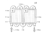
図1は、本発明の好ましい実施形態による電力変換装置10の構成を示す模式図である。
FIG. 1 is a schematic diagram showing a configuration of a
図1に示すように、本実施形態による電力変換装置10は、2つの電力変換部11,12と、これら2つの電力変換部11,12に対して共通に設けられた冷却機構19とを備えて構成されている。電力変換部11,12は、それぞれ主回路部11a,12aと温度センサ11b,12bとを有しており、スイッチング回路や整流回路を含む主回路部11a,12aの動作に伴って発生する熱は、対応する温度センサ11b,12bによって監視されている。つまり、各温度センサ11b,12bにはそれぞれ「過熱保護温度」が設定されており、対応する電力変換部11,12が過熱保護温度に達したことを検出すると、図示しない制御部は当該電力変換部の出力を停止若しくは制限し、これにより、主回路部11a,12aに含まれるFETやダイオードの熱による損傷が未然に防止している。温度センサ11b,12bとしては、例えばサーミスタを用いることができる。
As shown in FIG. 1, the
冷却機構19は、冷却水や空気等の冷媒19aが流れるパイプによって構成されており、パイプ内を冷媒19aが流れることによって電力変換部11,12が冷却される。通常の動作においては、この冷却機構19によって電力変換部11,12が十分に冷却されるのであるが、過負荷状態が長時間続いた場合や、冷却機構19に不具合が生じた場合などには、電力変換部11,12が異常過熱する可能性が考えられる。このような異常過熱は、上述のとおり、温度センサ11b,12bによって検出される。
The
図1に示すように、本実施形態では温度センサ11b,12bの位置が偏在しており、このため電力変換部11が電力変換部12の温度センサ12bに与える熱の影響の方が、電力変換部12が電力変換部11の温度センサ11bに与える熱の影響よりも大きくなっている。この点を考慮して、本実施形態では、電力変換部11の温度センサ11bの過熱保護温度を、電力変換部12の温度センサ12bの過熱保護温度よりも高く設定している。
As shown in FIG. 1, in the present embodiment, the positions of the temperature sensors 11b and 12b are unevenly distributed. Therefore, the influence of heat exerted on the temperature sensor 12b of the power conversion unit 12 by the
これにより、本実施形態では、電力変換部11,12を並列運転させた場合、必ず電力変換部12の方が先に過熱保護動作に入ることになる。上述のとおり、電力変換部12の温度センサ12bは相対的に電力変換部11による熱の影響を受けやすいことから、仮に電力変換部11が先に過熱保護動作に入ると、温度センサ12bは電力変換部11から受けていた熱の影響が低減若しくは無くなる分、電力変換部12の方は想定した温度で過熱保護動作に入ることができず、想定した温度よりもかなり高い温度まで通常動作を続けることになる。しかしながら、本実施形態では、必ず電力変換部12の方が先に過熱保護動作に入ることから上記のような問題は生じず、想定した温度で正しく過熱保護動作を行うことが可能となる。
Thereby, in this embodiment, when the
次に、電力変換装置10への過熱保護温度設定方法について説明する。
Next, an overheat protection temperature setting method for the
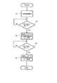
図2は、電力変換装置10への過熱保護温度設定方法を説明するためのフローチャートである。
FIG. 2 is a flowchart for explaining a method for setting the overheat protection temperature for the
図2に示すように、まず、冷却機構19に冷媒19aを流した状態で電力変換部11,12を並列運転させる(ステップS1)。これにより冷媒19aの温度は徐々に上昇する。冷媒19aの温度は、図示しない温度計により正確に測定されており、これがあらかじめ定められた第1の温度(例えば69.5℃)に達したか否かを判断する(ステップS2)。そして、第1の温度に達したことが検出されると(ステップS2:YES)、そのときの温度センサ12bの出力値を電力変換部12の過熱保護温度として設定する(ステップS3)。
As shown in FIG. 2, first, the
そして、引き続き冷媒19aの温度を測定し、これがあらかじめ定められた第2の温度(例えば70.0℃)に達したか否かを判断する(ステップS4)。そして、第2の温度に達したことが検出されると(ステップS4:YES)、そのときの温度センサ11bの出力値を電力変換部11の過熱保護温度として設定する(ステップS3)。 Then, the temperature of the refrigerant 19a is continuously measured, and it is determined whether or not this has reached a predetermined second temperature (for example, 70.0 ° C.) (step S4). When it is detected that the second temperature has been reached (step S4: YES), the output value of the temperature sensor 11b at that time is set as the overheat protection temperature of the power converter 11 (step S3).
以上により、電力変換装置10への過熱保護温度の設定が完了する。このような方法により過熱保護温度を設定すれば、実際の動作時においても、相対的に熱の影響を受けやすい電力変換部12の方が必ず先に過熱保護動作に入ることになる。
Thus, the setting of the overheat protection temperature for the
このように、本実施形態によれば、電力変換部11の温度センサ11bの過熱保護温度を、電力変換部12の温度センサ12bの過熱保護温度よりも高く設定していることから、相対的に熱の影響を受けやすい電力変換部12の方が必ず先に過熱保護動作に入ることになる。このため、電力変換部11,12とも、想定した温度で正しく過熱保護動作を行うことから、FETやダイオードの損傷を効果的に防止することが可能となる。
Thus, according to this embodiment, since the overheat protection temperature of the temperature sensor 11b of the
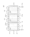
図3は、本発明の好ましい他の実施形態による電力変換装置20の構成を示す模式図である。
FIG. 3 is a schematic diagram showing a configuration of a
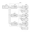
図3に示すように、本実施形態による電力変換装置20は、3つの電力変換部21〜23と、これら3つの電力変換部21〜23に対して共通に設けられた冷却機構19とを備えて構成されている。上記実施形態と同様、電力変換部21〜23は、それぞれ主回路部21a〜23aと温度センサ21b〜23bとを有している。本実施形態においても温度センサ21b〜23bはいずれも偏在して配置されており、このため電力変換部22の温度センサ22bは電力変換部21の熱の影響を強く受け、電力変換部23の温度センサ23bは電力変換部22の熱の影響を強く受けることになる。
As illustrated in FIG. 3, the
この場合、電力変換部22の温度センサ22bが他から受ける熱の影響と、電力変換部23の温度センサ23bが他から受ける熱の影響の大小を正確に評価することは困難であるが、隣接する2つの電力変換部をだけを抜き出して考えれば、どのように過熱保護温度を設定すべきか、容易に決定することができる。つまり、隣接する2つの電力変換部21,22を抜き出して考えれば、電力変換部21が電力変換部22の温度センサ22bに与える熱の影響の方が、電力変換部22が電力変換部21の温度センサ21bに与える熱の影響よりも大きいと言え、同じく、隣接する2つの電力変換部22,23を抜き出して考えれば、電力変換部22が電力変換部23の温度センサ23bに与える熱の影響の方が、電力変換部23が電力変換部22の温度センサ22bに与える熱の影響よりも大きいと言える。
In this case, it is difficult to accurately evaluate the influence of the heat received by the temperature sensor 22b of the
以上より、本実施形態では電力変換部21の温度センサ21bの過熱保護温度を、電力変換部22の温度センサ22bの過熱保護温度よりも高く設定し、且つ、電力変換部22の温度センサ22bの過熱保護温度を、電力変換部23の温度センサ23bの過熱保護温度よりも高く設定している。
As described above, in this embodiment, the overheat protection temperature of the temperature sensor 21b of the
これにより、電力変換部21〜23を並列運転させた場合、必ず電力変換部23が一番最初に過熱保護動作に入ることになり、その後、電力変換部22、電力変換部21の順で過熱保護動作に入ることになる。これにより、一部の電力変換部が過熱保護動作を行った場合であっても、残りの電力変換部が正常に過熱保護動作を行うことができることから、上記実施形態と同様、主回路部21a〜23aに含まれるFETやダイオードの損傷を効果的に防止することが可能となる。
As a result, when the
このような電力変換装置20への過熱保護温度設定方法は、図2を用いて説明した方法と同様であり、例えば、冷媒19aの温度が69.0℃に達した際に得られる温度センサ23bの出力値を電力変換部23の過熱保護温度として設定し、冷媒19aの温度が69.5℃に達した際に得られる温度センサ22bの出力値を電力変換部22の過熱保護温度として設定し、冷媒19aの温度が70.0℃に達した際に得られる温度センサ21bの出力値を電力変換部21の過熱保護温度として設定すればよい。
Such an overheat protection temperature setting method for the
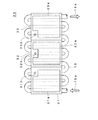
図4は、本発明の好ましいさらに他の実施形態による電力変換装置30の構成を示す模式図である。
FIG. 4 is a schematic diagram showing a configuration of a
図4に示すように、本実施形態による電力変換装置30は、3つの電力変換部31〜33と、これら3つの電力変換部31〜33に対して共通に設けられた冷却機構19とを備えて構成されている。上記各実施形態と同様、電力変換部31〜33は、それぞれ主回路部31a〜33aと温度センサ31b〜33bとを有している。本実施形態では、電力変換部31の温度センサ31b及び電力変換部33の温度センサ33bは、いずれも中央に位置する電力変換部32に近い位置に偏在して配置されており、電力変換部32の温度センサ32bは、電力変換部32のほぼ中心線上に配置されている。このため、電力変換部31の温度センサ31bは電力変換部32の熱の影響を強く受け、電力変換部33の温度センサ33bも電力変換部32の熱の影響を強く受けることになる。
As shown in FIG. 4, the
この場合、電力変換部32が電力変換部31の温度センサ31bに与える熱の影響の方が、電力変換部31が電力変換部32の温度センサ32bに与える熱の影響よりも大きいと言え、同じく、電力変換部32が電力変換部33の温度センサ33bに与える熱の影響の方が、電力変換部33が電力変換部32の温度センサ32bに与える熱の影響よりも大きいと言える。したがって、本実施形態では、電力変換部32の温度センサ32bの過熱保護温度を最も高く設定し、電力変換部31,33の温度センサ31b,33bの過熱保護温度を特に限定されないが同じ温度に設定すればよい。
In this case, it can be said that the influence of the heat which the
これにより、電力変換部31〜33を並列運転させた場合、必ず電力変換部31及び電力返還部33の一方が一番最初に過熱保護動作に入ることになり、その後、電力変換部31及び電力返還部33の他方、電力変換部32の順で過熱保護動作に入ることになる。電力変換部31と電力変換部33は物理的に十分離間しているので、これらが相互に与える熱の影響は極めて少なく、このため、これらの温度センサ31b,33bの過熱保護温度に差を付ける必要性は少ない。
Thus, when the
このような電力変換装置30への過熱保護温度設定方法も、図2を用いて説明した方法と同様であり、例えば、冷媒19aの温度が69.5℃に達した際に得られる温度センサ31b,33bの出力値をそれぞれ電力変換部31,33の過熱保護温度として設定し、冷媒19aの温度が70.0℃に達した際に得られる温度センサ32bの出力値を電力変換部32の過熱保護温度として設定すればよい。
Such an overheat protection temperature setting method for the
本発明による電力変換装置は、特に自動車用の電力変換装置として利用することが好適である。 The power conversion device according to the present invention is particularly preferably used as a power conversion device for automobiles.
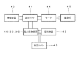
図5は、本発明による電力変換装置を備えた自動車の主要部分を概略的に示すブロック図である。 FIG. 5 is a block diagram schematically showing main parts of an automobile equipped with a power conversion device according to the present invention.
図5に示すように、本発明による電力変換装置を自動車用に用いた場合、電力変換装置10(20,30)は、高圧バッテリー41と電気機器42及び低圧バッテリー46との間に設けられ、高圧バッテリー41より供給される約120〜400Vの高電圧を約12Vに降圧してこれを電気機器42に供給するとともに、低圧バッテリー46を充電する役割を果たす。つまりこの場合、電力変換装置10(20,30)はDC/DCコンバータである。電気機器42としては、自動車に備えられるエアコンやオーディオ等が挙げられる。高圧バッテリー41への充電は、発電装置43より供給される電力によって行われる。高圧バッテリー41の出力はモータ44へも供給され、モータ44は、高圧バッテリー41より供給される高電圧(約120〜400V)に基づいて駆動系45を駆動する。尚、燃料電池車においては燃料電池本体が発電装置43となり、ハイブリッド車においてはモータ44が発電装置43を兼ねることになる。
As shown in FIG. 5, when the power conversion device according to the present invention is used for an automobile, the power conversion device 10 (20, 30) is provided between the high voltage battery 41, the
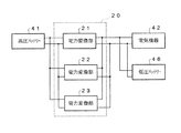
この場合、電気機器42及び低圧バッテリー46が1系統であれば、図6及び図7に示すように、電力変換装置10(20,30)に含まれる電力変換部を全て並列に接続すればよい。尚、図6は、電力変換装置10(図1参照)を構成する電力変換部11,12を並列接続した状態を示し、図7は、電力変換装置20(図3参照)を構成する電力変換部21〜23を並列接続した状態を示している。
In this case, if the
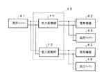
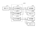
一方、電気機器42及び低圧バッテリー46が複数系統あれば、図8〜図10に示すように、電力変換装置10(20,30)に含まれる電力変換部の一部又は全部を個別に接続すればよい。尚、図8は、電力変換装置10(図1参照)を構成する電力変換部11,12をそれぞれ別系統の電気機器42及び低圧バッテリー46に接続した状態を示し、図9は、電力変換装置20(図3参照)を構成する電力変換部21,22と電力変換部23とをそれぞれ別系統の電気機器42及び低圧バッテリー46に接続した状態を示し、図10は、電力変換装置20(図3参照)を構成する電力変換部21〜23をそれぞれ別系統の電気機器42及び低圧バッテリー46に接続した状態を示している。
On the other hand, if there are a plurality of systems of
これらいずれの場合であっても本発明は有効であり、正常な過熱保護動作を行うことが可能となる。 In any of these cases, the present invention is effective, and a normal overheat protection operation can be performed.
本発明は、以上説明した実施の形態に限定されることなく、特許請求の範囲に記載された発明の範囲内で種々の変更が可能であり、それらも本発明の範囲内に包含されるものであることはいうまでもない。 The present invention is not limited to the embodiments described above, and various modifications are possible within the scope of the invention described in the claims, and these are also included in the scope of the present invention. Needless to say.
例えば、上記実施形態では、電力変換装置が2つ又は3つの電力変換部によって構成されている場合を例に説明したが、本発明による電力変換装置に含まれる電力変換部の数は、2つ以上であれば特に限定されない。 For example, in the above embodiment, the case where the power conversion device is configured by two or three power conversion units has been described as an example, but the number of power conversion units included in the power conversion device according to the present invention is two. If it is more, it will not specifically limit.
10,20,30 電力変換装置
11,12,21〜23,31〜33 電力変換部
11a,12a,21a〜23a,31a〜33a 主回路部
11b,12b,21b〜23b,31b〜33b 温度センサ
19 冷却機構
19a 冷媒
41 高圧バッテリー
42 電気機器
43 発電装置
44 モータ
45 駆動系
46 低圧バッテリー
10, 20, 30
Claims (8)
前記複数の電力変換部に対して共通に設けられた冷却機構に用いられる冷媒の温度が第1の温度に達した状態を、所定の電力変換部に設けられた温度センサの過熱保護温度に設定し、
前記冷媒の温度が前記第1の温度とは異なる第2の温度に達した状態を、前記所定の電力変換部とは異なる他の電力変換部に設けられた温度センサの過熱保護温度に設定することを特徴とする電力変換装置への過熱保護温度設定方法。 An overheat protection temperature setting method for a power conversion device including a plurality of power conversion units each having a temperature sensor,
The state in which the temperature of the refrigerant used in the cooling mechanism provided in common for the plurality of power conversion units has reached the first temperature is set as the overheat protection temperature of the temperature sensor provided in the predetermined power conversion unit. And
A state in which the temperature of the refrigerant has reached a second temperature different from the first temperature is set as an overheat protection temperature of a temperature sensor provided in another power converter different from the predetermined power converter. The overheat protection temperature setting method to the power converter characterized by the above-mentioned.
The influence of heat that the predetermined power conversion unit has on the temperature sensor of the other power conversion unit is smaller than the influence of heat that the other power conversion unit has on the temperature sensor of the predetermined power conversion unit, The temperature of 1 is lower than said 2nd temperature, The overheat protection temperature setting method to the power converter device of Claim 7 characterized by the above-mentioned.
Priority Applications (1)
| Application Number | Priority Date | Filing Date | Title |
|---|---|---|---|
| JP2004111316A JP4501505B2 (en) | 2004-04-05 | 2004-04-05 | Power converter |
Applications Claiming Priority (1)
| Application Number | Priority Date | Filing Date | Title |
|---|---|---|---|
| JP2004111316A JP4501505B2 (en) | 2004-04-05 | 2004-04-05 | Power converter |
Publications (2)
| Publication Number | Publication Date |
|---|---|
| JP2005295770A true JP2005295770A (en) | 2005-10-20 |
| JP4501505B2 JP4501505B2 (en) | 2010-07-14 |
Family
ID=35328082
Family Applications (1)
| Application Number | Title | Priority Date | Filing Date |
|---|---|---|---|
| JP2004111316A Expired - Fee Related JP4501505B2 (en) | 2004-04-05 | 2004-04-05 | Power converter |
Country Status (1)
| Country | Link |
|---|---|
| JP (1) | JP4501505B2 (en) |
Cited By (1)
| Publication number | Priority date | Publication date | Assignee | Title |
|---|---|---|---|---|
| EP1758196A1 (en) * | 2005-08-22 | 2007-02-28 | LG Electronics Inc. | Extingushing system for fuel cell |
Citations (3)
| Publication number | Priority date | Publication date | Assignee | Title |
|---|---|---|---|---|
| JPH07271457A (en) * | 1994-03-30 | 1995-10-20 | Omron Corp | Power unit |
| JP2001095233A (en) * | 1999-09-22 | 2001-04-06 | Tdk Corp | Switching power supply |
| JP2003018845A (en) * | 2001-06-29 | 2003-01-17 | Omron Corp | Power supply unit and power supply module |
-
2004
- 2004-04-05 JP JP2004111316A patent/JP4501505B2/en not_active Expired - Fee Related
Patent Citations (3)
| Publication number | Priority date | Publication date | Assignee | Title |
|---|---|---|---|---|
| JPH07271457A (en) * | 1994-03-30 | 1995-10-20 | Omron Corp | Power unit |
| JP2001095233A (en) * | 1999-09-22 | 2001-04-06 | Tdk Corp | Switching power supply |
| JP2003018845A (en) * | 2001-06-29 | 2003-01-17 | Omron Corp | Power supply unit and power supply module |
Cited By (1)
| Publication number | Priority date | Publication date | Assignee | Title |
|---|---|---|---|---|
| EP1758196A1 (en) * | 2005-08-22 | 2007-02-28 | LG Electronics Inc. | Extingushing system for fuel cell |
Also Published As
| Publication number | Publication date |
|---|---|
| JP4501505B2 (en) | 2010-07-14 |
Similar Documents
| Publication | Publication Date | Title |
|---|---|---|
| JP4591896B2 (en) | Vehicle equipped with a fuel cell power system | |
| US9106173B2 (en) | Motor driving device and method of protecting motor driving device | |
| JP6239020B2 (en) | Control device and control method for electric vehicle | |
| US9573580B2 (en) | Charge control device for hybrid vehicle | |
| US8294402B2 (en) | Bridge rectifier circuit | |
| US10296024B2 (en) | Semiconductor switch control device | |
| US20130039107A1 (en) | Discharge circuit for capacitor | |
| JP6056486B2 (en) | Vehicle power supply device | |
| US20200075977A1 (en) | System and method for maintaining insulation resistance of fuel cell | |
| JP2008204992A (en) | Power storage device | |
| US12178024B2 (en) | Cooling system with flow rate regulation | |
| KR20180134189A (en) | Plug-in vehicle and method of controlling thereof | |
| JP2010141984A (en) | Onboard charger device | |
| JP2009254206A (en) | Power source control system | |
| JP2006238675A (en) | Power conversion apparatus and method of setting overheat protection temperature therefor | |
| JP4103856B2 (en) | Cooling control device for vehicles with dual power source batteries | |
| JP4501505B2 (en) | Power converter | |
| JP5270602B2 (en) | Vehicle current limiting device | |
| WO2023223406A1 (en) | Electronic control device and electronic control method | |
| US20220134866A1 (en) | Motor vehicle and method for operation of a cooling device | |
| JP2009254209A (en) | Power supply control system | |
| KR101393584B1 (en) | Cooling fan monitoring system for fuel cell vehicle and method thereof | |
| US20230302876A1 (en) | Vehicle air conditioning control system | |
| JP5251556B2 (en) | Vehicle control device | |
| JP2006034006A (en) | DC-DC converter |
Legal Events
| Date | Code | Title | Description |
|---|---|---|---|
| A621 | Written request for application examination |
Free format text: JAPANESE INTERMEDIATE CODE: A621 Effective date: 20070309 |
|
| A977 | Report on retrieval |
Free format text: JAPANESE INTERMEDIATE CODE: A971007 Effective date: 20091217 |
|
| A131 | Notification of reasons for refusal |
Free format text: JAPANESE INTERMEDIATE CODE: A131 Effective date: 20091222 |
|
| A521 | Written amendment |
Free format text: JAPANESE INTERMEDIATE CODE: A523 Effective date: 20100209 |
|
| TRDD | Decision of grant or rejection written | ||
| A01 | Written decision to grant a patent or to grant a registration (utility model) |
Free format text: JAPANESE INTERMEDIATE CODE: A01 Effective date: 20100330 |
|
| A01 | Written decision to grant a patent or to grant a registration (utility model) |
Free format text: JAPANESE INTERMEDIATE CODE: A01 |
|
| A61 | First payment of annual fees (during grant procedure) |
Free format text: JAPANESE INTERMEDIATE CODE: A61 Effective date: 20100412 |
|
| R150 | Certificate of patent or registration of utility model |
Ref document number: 4501505 Country of ref document: JP Free format text: JAPANESE INTERMEDIATE CODE: R150 Free format text: JAPANESE INTERMEDIATE CODE: R150 |
|
| FPAY | Renewal fee payment (event date is renewal date of database) |
Free format text: PAYMENT UNTIL: 20130430 Year of fee payment: 3 |
|
| FPAY | Renewal fee payment (event date is renewal date of database) |
Free format text: PAYMENT UNTIL: 20140430 Year of fee payment: 4 |
|
| LAPS | Cancellation because of no payment of annual fees |