JP2005295761A - Power supply circuit - Google Patents
Power supply circuit Download PDFInfo
- Publication number
- JP2005295761A JP2005295761A JP2004110798A JP2004110798A JP2005295761A JP 2005295761 A JP2005295761 A JP 2005295761A JP 2004110798 A JP2004110798 A JP 2004110798A JP 2004110798 A JP2004110798 A JP 2004110798A JP 2005295761 A JP2005295761 A JP 2005295761A
- Authority
- JP
- Japan
- Prior art keywords
- power supply
- voltage
- supply circuit
- converter
- power
- Prior art date
- Legal status (The legal status is an assumption and is not a legal conclusion. Google has not performed a legal analysis and makes no representation as to the accuracy of the status listed.)
- Pending
Links
Images
Classifications
-
- Y—GENERAL TAGGING OF NEW TECHNOLOGICAL DEVELOPMENTS; GENERAL TAGGING OF CROSS-SECTIONAL TECHNOLOGIES SPANNING OVER SEVERAL SECTIONS OF THE IPC; TECHNICAL SUBJECTS COVERED BY FORMER USPC CROSS-REFERENCE ART COLLECTIONS [XRACs] AND DIGESTS
- Y02—TECHNOLOGIES OR APPLICATIONS FOR MITIGATION OR ADAPTATION AGAINST CLIMATE CHANGE
- Y02B—CLIMATE CHANGE MITIGATION TECHNOLOGIES RELATED TO BUILDINGS, e.g. HOUSING, HOUSE APPLIANCES OR RELATED END-USER APPLICATIONS
- Y02B70/00—Technologies for an efficient end-user side electric power management and consumption
- Y02B70/10—Technologies improving the efficiency by using switched-mode power supplies [SMPS], i.e. efficient power electronics conversion e.g. power factor correction or reduction of losses in power supplies or efficient standby modes
Landscapes
- Air Conditioning Control Device (AREA)
- Rectifiers (AREA)
Abstract
Description
本発明は、空気調和機等に使用される電源回路に係り、平滑用コンデンサ容量を可変制御し、効率改善を目標とした、電源回路に関するものである。 The present invention relates to a power supply circuit used for an air conditioner or the like, and more particularly to a power supply circuit that variably controls a smoothing capacitor capacity and aims to improve efficiency.
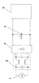
従来、この種の空気調和機の電源回路では、交流電源からの交流電圧はノイズフィルタを通った後ダイオードブリッジによって直流電圧に整流され、整流後の直流電圧が平滑用コンデンサにより平滑され、DC/DCコンバータにて一定の電圧値に変換され、各アクチュエータ等に出力される。(例えば特許文献1参照)
図3に示すように交流電源1と、ノイズフィルタ2と、ダイオードブリッジ3、平滑用コンデンサ4容量C1と、DC/DCコンバータ6から構成されている。
As shown in FIG. 3, the
従来、室内の空調を行う空気調和機の電源には、空気調和機の制御を行う制御系電源、リレー、ステッピングモーター等の各種駆動機構(アクチュエータ等)を駆動するためのパワー系電源とファンモータを駆動させる電源が必要である。例えば、制御系電源として5V、パワー系電源として12Vの直流電圧、ファンモータ駆動用電源として0〜40V可変直流電圧が必要とされるため、コンデンサは二次側最大出力供給に充分な大容量のものを要求される。しかしながら、空気調和機の待機時には、可変直流電圧の必要はなく、制御系回路を動作させるための一定電圧5Vが必要なだけであるため、コンデンサ容量は運転時に比べ低容量ですむが、最大出力供給に合わせた大容量のままである。この容量の差が力率を悪くし、不要電力損失となり、待機時消費電力を増加させる原因となっている。 Conventionally, air conditioners that perform indoor air conditioning include power supplies for controlling air conditioners, power supplies for driving various drive mechanisms (actuators, etc.) such as relays and stepping motors, and fan motors. A power supply for driving is required. For example, a DC voltage of 5V is required as a control system power supply, a DC voltage of 12V as a power system power supply, and a 0-40V variable DC voltage as a power supply for driving a fan motor. Therefore, the capacitor has a large capacity sufficient to supply the secondary side maximum output. What is required. However, when the air conditioner is on standby, there is no need for variable DC voltage, and only a constant voltage of 5 V is required to operate the control system circuit. It remains a large capacity to match the supply. This difference in capacity deteriorates the power factor, resulting in unnecessary power loss, and increases standby power consumption.
上記課題を解決するために本発明の電源回路は、DC/DCコンバータの二次側負荷レベルを検出し、その検出値に基づき前記複数の平滑用コンデンサを選択して接続するようにしたもので、この構成により平滑用コンデンサの容量はDC/DCコンバータの二次側負荷レベルに合わせて大容量と低容量に切り換えることにより、力率を改善し、待機時消費電力を低減させることができる。 In order to solve the above problems, a power supply circuit according to the present invention detects a secondary load level of a DC / DC converter and selects and connects the plurality of smoothing capacitors based on the detected value. With this configuration, the capacity of the smoothing capacitor can be switched between a large capacity and a low capacity according to the secondary load level of the DC / DC converter, thereby improving the power factor and reducing standby power consumption.
本発明の電源回路は、力率を改善することができ、効率よく電力を消費するので、その結果、待機時消費電力が低減することができる。 The power supply circuit of the present invention can improve the power factor and consume power efficiently, and as a result, standby power consumption can be reduced.
第1の発明は、電源回路を構成している平滑用コンデンサに切り換え手段を設け、切り換え手段により平滑用コンデンサの容量を可変し減少させ、力率を改善し、消費電力を低減させることができる。 According to the first aspect of the present invention, switching means is provided in the smoothing capacitor constituting the power supply circuit, and the capacity of the smoothing capacitor can be varied and reduced by the switching means, thereby improving the power factor and reducing power consumption. .
第2の発明は、コモンモードチョークコイルの性質を利用して、等価的にインダクタンスとして作用させ、力率を改善し、消費電力を低減させることができる。 The second aspect of the invention makes it possible to act equivalently as an inductance by utilizing the properties of the common mode choke coil, improve the power factor, and reduce power consumption.
第3の発明は、第1または第2の発明の電源回路を空気調和機に搭載して、空気調和機待機時に平滑用コンデンサの容量を減少させ、力率を改善し、待機時消費電力を低減させ
ることができる。
According to a third aspect of the present invention, the power supply circuit of the first or second aspect is mounted on an air conditioner, the capacity of the smoothing capacitor is reduced during standby of the air conditioner, power factor is improved, and standby power consumption is reduced. Can be reduced.
以下、本発明の実施の形態について、図面を参照しながら説明する。なお、この実施の形態によって本発明が限定されるものではない。 Hereinafter, embodiments of the present invention will be described with reference to the drawings. Note that the present invention is not limited to the embodiments.
(実施の形態1)
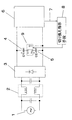
図1は本発明の実施の形態1における電源回路のブロック図である。
(Embodiment 1)
FIG. 1 is a block diagram of a power supply circuit according to
従来例の図3において、平滑用コンデンサをコンデンサ4容量C1とコンデンサ2容量C2の2個直列にして、その間に切り換え手段9を設け、DC/DCコンバータ6の二次側負荷レベルを検出して、その検出レベル情報7に基づいて、切り換えを指示する切り換え指示手段8を有する構成となっている。ここで、C1=C2とする。この時の平滑用コンデンサ容量はC1/2である。以上のように構成された制御ブロックについて、以下その動作、作用を説明する。
In FIG. 3 of the conventional example, two smoothing capacitors, a
空気調和機が運転動作を始めると各種駆動機構(アクチュエータ等)や制御系回路を駆動させるために、二次側電力の充分な供給が必要となるため、コンデンサは大容量のものを要求される。一方、空気調和機が運転待機時には、制御系回路の動作のみ必要となるだけで、コンデンサは低容量のもので十分である。 When the air conditioner starts operation, it is necessary to supply a sufficient amount of secondary power to drive various drive mechanisms (actuators, etc.) and control system circuits. . On the other hand, when the air conditioner is on standby, only the operation of the control system circuit is required, and a capacitor having a low capacity is sufficient.
このことから、DC/DCコンバータ6の二次側負荷レベルを検出し、その検出した二次側負荷レベル情報7が所定値より大きい場合に、切り換え手段9において、端子S1と端子S3を接続して、平滑用コンデンサをコンデンサ4容量C1のみとして、平滑用コンデンサの総容量を増加することができる。
From this, the secondary load level of the DC /
以上のように、本実施の形態1では、二次側負荷レベルにより平滑用コンデンサ容量を切り換えることで、電流実効値を低減させ、コンバータが消費する電力、電圧は一定であるため、下記(式1)及び(式2)より力率を改善することができ、電力損失を低減し、空気調和機の待機時消費電力を低減することができる。
P=Eicosθ(式1)
cosθ=R/√(R2+(ωL−1/ωC)2)(式2)
次に、Pは高圧直流電圧変換後の電力、Eは電圧実効値、Iは電流実効値、Lはインダクタンス、Cはコンデンサ容量、Rは抵抗、cosθは力率を表す。
As described above, in the first embodiment, the effective current value is reduced by switching the smoothing capacitor capacity according to the secondary load level, and the power and voltage consumed by the converter are constant. Power factor can be improved from 1) and (Formula 2), power loss can be reduced, and standby power consumption of the air conditioner can be reduced.
P = Eicos θ (Formula 1)
cos θ = R / √ (R 2 + (ωL−1 / ωC) 2 ) (Formula 2)
Next, P is the power after high-voltage DC voltage conversion, E is the effective voltage value, I is the effective current value, L is the inductance, C is the capacitor capacity, R is the resistance, and cos θ is the power factor.
次に、待機時消費電力低減の詳細な説明を行うと、例えば、図1で空気調和機の待機時消費電力(入力電圧)Pinは0.8Wで、力率は35%とすると、実際に高圧直流電圧変換後の電力Pは、下記(数3)より0.28Wと求められる。この力率を本発明により、仮に70%まで改善したとすると、(数3)より、待機時消費電力Pinは0.4Wとなり、待機時消費電力を低減することができる。
Pin=P・cosθ(式3)
ここで、Pinは空気調和機の待機時消費電力、Pは高圧直流電圧変換後の電力を示す。
Next, a detailed description of standby power consumption reduction will be given. For example, in FIG. 1, when the standby power consumption (input voltage) Pin of the air conditioner is 0.8 W and the power factor is 35%, The electric power P after the high-voltage DC voltage conversion is obtained as 0.28 W from the following (Equation 3). If this power factor is improved to 70% according to the present invention, standby power consumption Pin is 0.4 W from (Equation 3), and standby power consumption can be reduced.
Pin = P · cos θ (Formula 3)
Here, Pin indicates standby power consumption of the air conditioner, and P indicates power after high-voltage DC voltage conversion.
(実施の形態2)
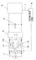
図2は本発明の実施の形態2における電源回路の制御ブロック図であり、本実施の形態2の電源回路の回路構成、動作は基本的に実施の形態1と同じである。
(Embodiment 2)
FIG. 2 is a control block diagram of the power supply circuit according to the second embodiment of the present invention. The circuit configuration and operation of the power supply circuit according to the second embodiment are basically the same as those of the first embodiment.
実施の形態1のように、複数の平滑用コンデンサの切り換え手段による切り換えでは、複数の平滑コンデンサを配置するスペースやコストが発生してしまう。そのため、本実施の形態では、図2に示すように全波整流直流電圧を低電圧に変換するスイッチング電源の
ノイズ低減用のノイズフィルタをDC/DCコンバータ6の二次側負荷レベルの検出レベル情報7に基づいて、切り換え手段14により、ノイズフィルタ10とノイズフィルタ11と切り換えられるように設けている。
As in the first embodiment, when the plurality of smoothing capacitors are switched by the switching means, a space and cost for arranging the plurality of smoothing capacitors are generated. Therefore, in the present embodiment, as shown in FIG. 2, the noise filter for noise reduction of the switching power supply that converts the full-wave rectified DC voltage into a low voltage is used as the detection level information of the secondary load level of the DC /
また、このノイズフィルタ10は対称形コモンモードチョークコイル12で構成されており、ノイズフィルタ11は非対称形コモンモードチョークコイル13で構成されている。理想的なコモンモードチョークコイルは互いに磁束を打ち消すように働き、回路上では作用していないことと同等である。そこで、コイルを中心から見て、非対称形にすることで、打ち消しあうことのできない磁束が増加され、等価的にノーマルモードチョーク成分を増加することとなり、一次回路インダクタンスとして作用させることができる。
The
前記実施の形態1のように、二次側負荷レベル情報7が所定値より小さい場合に切り換え手段9において、端子S3と端子S4を接続して、非対称形のコモンモードチョークコイルで構成されたノイズフィルタ13を選択して、インダクタンスを増加させることで、(式2)より、力率を改善し電力損失を低減し、空気調和機の消費電力をさらに低減し、さらに平滑用コンデンサより小さく、安価であるノイズフィルタを使用することで、基板の小型化、低コスト化を行うことができる。
As in the first embodiment, when the secondary
以上のように、本発明にかかる電源回路は、待機時消費電力の低減が可能となるので、リモコンを備えていて機器としての消費電力が大きい電子・電気機器の効率改善を目標とした電源回路の用途にも適応できる。 As described above, since the power supply circuit according to the present invention can reduce standby power consumption, the power supply circuit is provided with a remote control and is aimed at improving the efficiency of electronic and electrical equipment that consumes a large amount of power as equipment. It can be adapted to other uses.
1 交流電圧
2 ノイズフィルタ
3 ダイオードブリッジ
4 コンデンサ容量C1
5 コンデンサ容量C2
6 DC/DCコンバータ
7 二次側負荷レベル情報
8 切り換え指示手段
9 切り換え手段
10 ノイズフィルタ
11 ノイズフィルタ
12 コモンモードチョークコイル(対称形)
13 コモンモードチョークコイル(非対称形)
14 切り換え手段
1
5 Capacitor capacity C2
6 DC /
13 Common mode choke coil (asymmetric type)
14 Switching means
Claims (3)
Priority Applications (1)
| Application Number | Priority Date | Filing Date | Title |
|---|---|---|---|
| JP2004110798A JP2005295761A (en) | 2004-04-05 | 2004-04-05 | Power supply circuit |
Applications Claiming Priority (1)
| Application Number | Priority Date | Filing Date | Title |
|---|---|---|---|
| JP2004110798A JP2005295761A (en) | 2004-04-05 | 2004-04-05 | Power supply circuit |
Publications (1)
| Publication Number | Publication Date |
|---|---|
| JP2005295761A true JP2005295761A (en) | 2005-10-20 |
Family
ID=35328075
Family Applications (1)
| Application Number | Title | Priority Date | Filing Date |
|---|---|---|---|
| JP2004110798A Pending JP2005295761A (en) | 2004-04-05 | 2004-04-05 | Power supply circuit |
Country Status (1)
| Country | Link |
|---|---|
| JP (1) | JP2005295761A (en) |
Cited By (2)
| Publication number | Priority date | Publication date | Assignee | Title |
|---|---|---|---|---|
| JP2006280135A (en) * | 2005-03-30 | 2006-10-12 | Kyocera Mita Corp | Electrical apparatus and converter |
| JP2010226925A (en) * | 2009-03-25 | 2010-10-07 | Dx Antenna Co Ltd | Protection circuit |
-
2004
- 2004-04-05 JP JP2004110798A patent/JP2005295761A/en active Pending
Cited By (2)
| Publication number | Priority date | Publication date | Assignee | Title |
|---|---|---|---|---|
| JP2006280135A (en) * | 2005-03-30 | 2006-10-12 | Kyocera Mita Corp | Electrical apparatus and converter |
| JP2010226925A (en) * | 2009-03-25 | 2010-10-07 | Dx Antenna Co Ltd | Protection circuit |
Similar Documents
| Publication | Publication Date | Title |
|---|---|---|
| US11128247B2 (en) | DC to DC converter sourcing variable DC link voltage | |
| US10807476B2 (en) | Electrical system for charging a high-voltage battery and a low-voltage battery | |
| JP2015144554A (en) | Power converter | |
| JP5031444B2 (en) | Electrical equipment with a noise filter circuit | |
| US11336181B2 (en) | DC to DC converter sourcing variable DC link voltage | |
| JP5563425B2 (en) | Power supply | |
| JPH11289766A (en) | Power supply | |
| WO2011012984A1 (en) | Electric power conversion device | |
| JP2018078756A (en) | Power converter and air conditioner using the same | |
| JP6106372B2 (en) | Lighting power supply device and lighting fixture | |
| JP2006280135A (en) | Electrical apparatus and converter | |
| JP2009100554A (en) | Partial voltage resonance type switching power supply circuit and air conditioner equipped with the same | |
| JP2011024306A (en) | Switching power supply apparatus | |
| JP2005295761A (en) | Power supply circuit | |
| JP4300758B2 (en) | Power supply device for image forming apparatus and image forming apparatus | |
| JP2000308352A (en) | Control device for air conditioner | |
| CN103380338B (en) | Power circuit and heat pump unit | |
| JP4674122B2 (en) | Power supply | |
| CN218920271U (en) | Isolated double-path output voltage reduction circuit, power supply unit and air conditioner | |
| CN220382954U (en) | Efficient switching power supply circuit | |
| JP4722541B2 (en) | Power supply device and air conditioner using the same | |
| JP7517202B2 (en) | Motor Control Device | |
| CN213990521U (en) | Rectifying circuit, device and electrical equipment | |
| JP2008136316A (en) | Charging device for power supply and charging method for power supply | |
| JP7428730B2 (en) | power converter |