JP2005295725A - Thermoelectric generator - Google Patents
Thermoelectric generator Download PDFInfo
- Publication number
- JP2005295725A JP2005295725A JP2004109294A JP2004109294A JP2005295725A JP 2005295725 A JP2005295725 A JP 2005295725A JP 2004109294 A JP2004109294 A JP 2004109294A JP 2004109294 A JP2004109294 A JP 2004109294A JP 2005295725 A JP2005295725 A JP 2005295725A
- Authority
- JP
- Japan
- Prior art keywords
- thermoelectric conversion
- thermoelectric
- temperature
- conversion module
- cooling water
- Prior art date
- Legal status (The legal status is an assumption and is not a legal conclusion. Google has not performed a legal analysis and makes no representation as to the accuracy of the status listed.)
- Pending
Links
Images


Classifications
-
- F—MECHANICAL ENGINEERING; LIGHTING; HEATING; WEAPONS; BLASTING
- F01—MACHINES OR ENGINES IN GENERAL; ENGINE PLANTS IN GENERAL; STEAM ENGINES
- F01N—GAS-FLOW SILENCERS OR EXHAUST APPARATUS FOR MACHINES OR ENGINES IN GENERAL; GAS-FLOW SILENCERS OR EXHAUST APPARATUS FOR INTERNAL-COMBUSTION ENGINES
- F01N13/00—Exhaust or silencing apparatus characterised by constructional features
- F01N13/009—Exhaust or silencing apparatus characterised by constructional features having two or more separate purifying devices arranged in series
-
- F—MECHANICAL ENGINEERING; LIGHTING; HEATING; WEAPONS; BLASTING
- F01—MACHINES OR ENGINES IN GENERAL; ENGINE PLANTS IN GENERAL; STEAM ENGINES
- F01N—GAS-FLOW SILENCERS OR EXHAUST APPARATUS FOR MACHINES OR ENGINES IN GENERAL; GAS-FLOW SILENCERS OR EXHAUST APPARATUS FOR INTERNAL-COMBUSTION ENGINES
- F01N5/00—Exhaust or silencing apparatus combined or associated with devices profiting by exhaust energy
- F01N5/02—Exhaust or silencing apparatus combined or associated with devices profiting by exhaust energy the devices using heat
- F01N5/025—Exhaust or silencing apparatus combined or associated with devices profiting by exhaust energy the devices using heat the device being thermoelectric generators
-
- Y—GENERAL TAGGING OF NEW TECHNOLOGICAL DEVELOPMENTS; GENERAL TAGGING OF CROSS-SECTIONAL TECHNOLOGIES SPANNING OVER SEVERAL SECTIONS OF THE IPC; TECHNICAL SUBJECTS COVERED BY FORMER USPC CROSS-REFERENCE ART COLLECTIONS [XRACs] AND DIGESTS
- Y02—TECHNOLOGIES OR APPLICATIONS FOR MITIGATION OR ADAPTATION AGAINST CLIMATE CHANGE
- Y02T—CLIMATE CHANGE MITIGATION TECHNOLOGIES RELATED TO TRANSPORTATION
- Y02T10/00—Road transport of goods or passengers
- Y02T10/10—Internal combustion engine [ICE] based vehicles
- Y02T10/12—Improving ICE efficiencies
Landscapes
- Engineering & Computer Science (AREA)
- Chemical & Material Sciences (AREA)
- Combustion & Propulsion (AREA)
- Mechanical Engineering (AREA)
- General Engineering & Computer Science (AREA)
- Exhaust Gas After Treatment (AREA)
Abstract
【課題】 運転条件に応じて適切な電力量を回収することが可能な熱電発電装置を提供する。
【解決手段】 エンジン40の排気管41上に配置される熱電素子を有する第1の熱電変換スタック1と第2の熱電変化スタック2を備える。各熱電変換スタック1、2には、冷却水配管L1〜L6が接続されており、この冷却水配管上には、スタック1、2に供給される冷却水比率を変更するための流量制御弁72、74が設けられている。制御ECU60は、温度計61、63、流量計62の検出結果を参照して各流量制御弁72、74を調整し、各スタック1、2に供給される冷却水の比率を変更する。
【選択図】 図1
PROBLEM TO BE SOLVED: To provide a thermoelectric generator capable of recovering an appropriate amount of electric power according to operating conditions.
SOLUTION: A first thermoelectric conversion stack 1 and a second thermoelectric change stack 2 having thermoelectric elements arranged on an exhaust pipe 41 of an engine 40 are provided. Cooling water pipes L1 to L6 are connected to the thermoelectric conversion stacks 1 and 2, and a flow rate control valve 72 for changing the ratio of the cooling water supplied to the stacks 1 and 2 is provided on the cooling water pipes. , 74 are provided. The control ECU 60 refers to the detection results of the thermometers 61 and 63 and the flow meter 62 and adjusts the flow control valves 72 and 74 to change the ratio of the cooling water supplied to the stacks 1 and 2.
[Selection] Figure 1
Description
本発明は、熱エネルギーを電気エネルギーへ変換することにより発電を行う熱電発電装置に関する。 The present invention relates to a thermoelectric generator that generates power by converting thermal energy into electrical energy.
自動車のエンジンや、工場のボイラー等から排出される排ガスの持つ熱エネルギーを電力として回収する装置として熱電発電装置が知られている(例えば、特許文献1参照)。この特許文献1の技術では、排ガス流の上流側に高温領域で作動する高温用熱電変換モジュールを配置し、下流側にこれより低温領域で作動する低温用熱電変換モジュールを配置して、耐熱性を向上させるとともに、それぞれの作動温度を適正なものとすることで、発電装置全体としての発電効率を向上させている。
ところで、この種の熱電発電装置においては、各熱電変換モジュールに冷却水を循環させて冷却している。そして、冷却水循環用に電動ポンプ等の動力源を用いているが、作動条件によっては熱電変換モジュールによって得られる電力に比較して電動ポンプの作動に必要な電力が大きく、実際に回収される電力量が少なくなることがある。 By the way, in this kind of thermoelectric power generator, cooling water is circulated through each thermoelectric conversion module to cool it. A power source such as an electric pump is used for circulating the cooling water, but depending on the operating conditions, the electric power required for the operation of the electric pump is larger than the electric power obtained by the thermoelectric conversion module, and the electric power actually recovered The amount may be reduced.
そこで本発明は、運転条件に応じて適切な電力量を回収することが可能な熱電発電装置を提供することを課題とする。 Then, this invention makes it a subject to provide the thermoelectric power generator which can collect | recover appropriate electric energy according to driving | running conditions.
上記課題を解決するため、本発明に係る熱電発電装置は、熱媒流路の上流側に配置され、この熱媒流路を流れる熱媒と供給される冷媒との温度差により起電力を生ずる熱電素子を有する第1の熱電変換モジュールと、この熱媒流路の下流側に配置され、熱媒流路を流れる熱媒と供給される冷媒との温度差により起電力を生ずる熱電素子を有する第2の熱電変換モジュールとを備える熱電発電装置であって、第1の熱電変換モジュールと第2の熱電変換モジュールに供給する冷媒の比率を変更する比率変更手段を備えていることを特徴とする。 In order to solve the above problems, the thermoelectric power generation device according to the present invention is disposed upstream of the heat medium flow path, and generates an electromotive force due to a temperature difference between the heat medium flowing through the heat medium flow path and the supplied refrigerant. A first thermoelectric conversion module having a thermoelectric element, and a thermoelectric element that is arranged downstream of the heat medium flow path and generates an electromotive force due to a temperature difference between the heat medium flowing through the heat medium flow path and the supplied refrigerant. A thermoelectric power generation apparatus comprising a second thermoelectric conversion module, characterized by comprising ratio changing means for changing a ratio of refrigerant supplied to the first thermoelectric conversion module and the second thermoelectric conversion module. .
熱電変換モジュールの熱電素子が発生する起電力は、高温側温度と低温側温度の両方に依存する。本発明では、第1の熱電変換モジュールと第2の熱電変換モジュールとに供給される冷媒の比率を変更することで、各熱電変換モジュールに供給される冷媒の流量を調整することで、各熱電変換モジュールにおいて適正な電力が得られるよう、低温側の温度を調整する。 The electromotive force generated by the thermoelectric element of the thermoelectric conversion module depends on both the high temperature side temperature and the low temperature side temperature. In the present invention, by changing the ratio of the refrigerant supplied to the first thermoelectric conversion module and the second thermoelectric conversion module, and adjusting the flow rate of the refrigerant supplied to each thermoelectric conversion module, each thermoelectric conversion The temperature on the low temperature side is adjusted so that proper power is obtained in the conversion module.
なお、熱電変換モジュールをさらに多段構成とし、各熱電変換モジュールに供給する冷媒の比率を変更する構成についても上記に係る発明に含まれる。また、比率変更には、一方の熱電変換モジュールのみに冷媒を供給し、他方には冷媒を供給しない場合も含まれる。本発明にいう熱媒としては、内燃機関を含む燃焼機器の排ガスのほか高温排水等が挙げられる。また、本発明にいう冷媒としては、冷却水のほか各種の液体や、空気その他のガス、さらには相変化する媒体であってもよい。 In addition, the invention which concerns on the above also includes the structure which makes a thermoelectric conversion module multistage structure, and changes the ratio of the refrigerant | coolant supplied to each thermoelectric conversion module. The ratio change includes a case where the refrigerant is supplied only to one thermoelectric conversion module and the other is not supplied with the refrigerant. Examples of the heat medium referred to in the present invention include exhaust gas from combustion equipment including an internal combustion engine and high-temperature waste water. Moreover, as a refrigerant | coolant said to this invention, various liquids other than cooling water, air, other gas, and also the medium which changes a phase may be sufficient.
熱媒の温度・流量および冷媒の温度を判定し、判定結果に基づいて前記比率変更手段の動作を制御するとよい。あるいは、第1および第2の熱電変換モジュールの少なくともいずれかの一方の高温側、低温側温度を判定し、判定結果に基づいて比率変更手段の動作を制御してもよい。また、第1および第2の熱電変換モジュールによる起電力を測定し、測定結果に基づいて比率変更手段の動作を制御してもよい。 The temperature / flow rate of the heat medium and the temperature of the refrigerant may be determined, and the operation of the ratio changing unit may be controlled based on the determination result. Alternatively, the high temperature side or low temperature side temperature of at least one of the first and second thermoelectric conversion modules may be determined, and the operation of the ratio changing unit may be controlled based on the determination result. Moreover, the electromotive force by the 1st and 2nd thermoelectric conversion module may be measured, and operation | movement of a ratio change means may be controlled based on a measurement result.
第1、第2の熱電変換モジュールの起電力を直接測定するか、起電力を決定づける状態量である高温側、低温側の温度、または、熱媒の温度・流量、冷媒の温度を判定することにより起電力が適正となるよう比率変更手段の動作を制御する。 Directly measure the electromotive force of the first and second thermoelectric conversion modules, or determine the temperature on the high temperature side, the low temperature side, the temperature / flow rate of the heating medium, or the temperature of the refrigerant, which is a state quantity that determines the electromotive force Thus, the operation of the ratio changing means is controlled so that the electromotive force becomes appropriate.
熱媒流路は、燃焼機器の排気系であって、第1の熱電変換モジュールと第2の熱電変換モジュールとの間に排気浄化触媒を備えており、触媒の温度が所定以下の場合には、少なくとも第1の熱電変換モジュールへの冷媒供給を停止するとよい。 The heat medium flow path is an exhaust system for combustion equipment, and includes an exhaust purification catalyst between the first thermoelectric conversion module and the second thermoelectric conversion module, and when the temperature of the catalyst is equal to or lower than a predetermined value. The refrigerant supply to at least the first thermoelectric conversion module may be stopped.
例えば、触媒の温度が低い冷間始動時には、触媒より上流側に存在する第1の熱電変換モジュールを作動させると、触媒へ流入する排ガス温度が低下して、触媒の昇温に時間を要し、昇温までの間のエミッションが悪化するため、第1の熱電変換モジュールへの冷媒供給を停止し、触媒へ流入する排ガス温度の低下を防ぐ。同様に、排ガス温度が低い場合や、排ガス流入量が少ない(自動車のエンジンの場合は低速低負荷時)場合も第1の熱電変換モジュールへの冷媒供給を停止し、触媒へ流入する排ガス温度の低下を防ぐ。 For example, at the time of cold start where the temperature of the catalyst is low, if the first thermoelectric conversion module existing on the upstream side of the catalyst is operated, the temperature of the exhaust gas flowing into the catalyst decreases, and it takes time to raise the temperature of the catalyst. Since the emission until the temperature rises worsens, the refrigerant supply to the first thermoelectric conversion module is stopped, and the exhaust gas temperature flowing into the catalyst is prevented from decreasing. Similarly, when the exhaust gas temperature is low or when the exhaust gas inflow amount is small (low speed and low load in the case of an automobile engine), the refrigerant supply to the first thermoelectric conversion module is stopped and the exhaust gas temperature flowing into the catalyst is reduced. Prevent decline.
本発明によれば、冷媒の流量比率を調整することで第1の熱電変換モジュールと第2の熱電変換モジュールのそれぞれが効率よく発電できるようそれぞれの低温側温度を調整する。このように冷却条件を制御することで、実際に回収される電力(発電電力−冷媒供給に必要な電力)の向上が図れる。 According to the present invention, by adjusting the flow rate ratio of the refrigerant, each low temperature side temperature is adjusted so that each of the first thermoelectric conversion module and the second thermoelectric conversion module can generate power efficiently. By controlling the cooling conditions in this way, it is possible to improve the actually recovered power (generated power—power necessary for supplying the refrigerant).
起電力や起電力を決定づける状態量を基にして、この冷却条件を制御することで、精度よく制御を行うことができるとともに、制御性も向上する。 By controlling the cooling condition based on the electromotive force and the state quantity that determines the electromotive force, the control can be performed with high accuracy and the controllability is also improved.
熱電変換モジュールが排気浄化触媒をはさんで配置されている場合には、触媒温度を参照して冷却条件制御を行うことで、触媒の暖機性を向上させるとともに、触媒温度が低下するのを抑制して、エミッションの悪化を抑制することができる。 When the thermoelectric conversion module is placed across the exhaust purification catalyst, the cooling condition control is performed with reference to the catalyst temperature, thereby improving the warm-up property of the catalyst and reducing the catalyst temperature. It is possible to suppress the deterioration of emission.
以下、添付図面を参照して本発明の好適な実施の形態について詳細に説明する。説明の理解を容易にするため、各図面において同一の構成要素に対しては可能な限り同一の参照番号を附し、重複する説明は省略する。 DESCRIPTION OF EXEMPLARY EMBODIMENTS Hereinafter, preferred embodiments of the invention will be described in detail with reference to the accompanying drawings. In order to facilitate the understanding of the description, the same reference numerals are given to the same components in the drawings as much as possible, and duplicate descriptions are omitted.
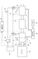
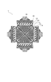
図1は、本発明に係る熱電発電装置の第1の実施形態を搭載した車両の排気系を示す概略構成図であり、図2は、その熱電発電装置の第1の熱電変換スタック1部分の断面図(図1のII−II線断面図)であり、図3は、その熱電変換モジュール10部分の拡大断面図である。
FIG. 1 is a schematic configuration diagram showing an exhaust system of a vehicle equipped with a first embodiment of a thermoelectric generator according to the present invention, and FIG. 2 shows a first
この熱電発電装置は、エンジン40に接続された排気管41上に配置されており、上流側から第1の熱電変換スタック1と、第2の熱電変換スタック2が、排気浄化触媒3をはさんで配置されている。ここで、第1の熱電変換スタック1と第2の熱電変換スタック2は、搭載する熱電素子の特性が異なるほかは、同様の構成をとっている。
This thermoelectric generator is arranged on an
図2に示されるように、第1の熱電変換スタック1は、第1の熱電素子100を有する第1の熱電変換モジュール10と、排気管内に配置される熱回収フィン(集熱フィン)13と、内部に冷却水を循環させる通路を有する冷却ケース15とを4組組み合わせて構成されている。
As shown in FIG. 2, the first
集熱フィン13は、平板状の基部に、その一方の表面から排気の流れ方向に所定の間隔で平行に延びる板状の多数のフィンが一体的に成形されているものである。この集熱フィン13は、アルミ、銅、ステンレス等の熱伝導性が良好な金属のほか、AlN、SiC等の高熱伝導性のセラミックスで形成されている。
The
集熱フィン13の各フィンの高さ、つまり、先端部から根本までの距離は、中央に位置するフィンが最も高く、周縁部へ行くほど低くなる構成を採る。各フィンの先端部を結んだ線は垂直二等辺三角形の垂直角をはさむ2辺の形状に合致するいわゆる楔形の形状をなしている。
The height of each fin of the
この集熱フィン13のフィン形成面と反対の表面側に、絶縁材11をはさんで、熱電変換モジュール10の高温側端面が配置される。そして、熱電変換モジュール10の反対面の低温側端面には、絶縁材12をはさんで、冷却ケース15が配置される。
On the surface side opposite to the fin forming surface of the
集熱フィン13のフィン先端側を覆うように、断面が略L字形のガイド板14が配置されている。ガイド板14〜冷却ケース15までを組み合わせた状態で、固定部材16によって排気管41に固定することで、第1の熱電変換スタック1が得られる。組み立てられた状態では、4個のガイド板14の排気流れ方向に直交する断面形状は、図2に示されるようにX字状になる。
A
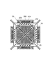
第2の熱電変換スタック2も、上述したように同様の構成を有しており、本段落の以下の説明においては、図2における各参照番号1xを2xと読み替えるものとする。つまり、第2の熱電変換スタック2は、第2の熱電素子200を有する第2の熱電変換モジュール20と、排気管内に配置される集熱フィン23と、内部に冷却水を循環させる通路を有する冷却ケース25と、絶縁材21、22と、ガイド板24とを組み合わせた組立体4組を固定部材26によって排気管41に固定したものである。なお、各部材の素材、形状は第1の熱電変換スタック1と同じ構成でもよいが、内部を通過する排ガス温度が第1の熱電変換スタック1の場合より低く、第1の熱電変換スタック1ほどの耐熱性は要求されないことから、異なる素材や形状としてもよい。
The second
なお、第1、第2の熱電変換スタック1、2内では、さらに、こうして形成されるスタックを排気の流れ方向に複数個配置することで、熱電変換モジュール10または20を排気の流れ方向に多段に配置してもよい。
In the first and second thermoelectric conversion stacks 1 and 2, a plurality of stacks formed in this manner are arranged in the exhaust flow direction, so that the
第1、第2の熱電変換スタック1、2内の各冷却ケース15、25の冷却水通路は直列に接続しても、並列に接続してもどちらでもよく、排ガスの流れ方向に直交する同一断面内の冷却ケース15、25間では並列に、流れ方向で異なる位置に位置する冷却ケース15、25間では直列に接続することも可能である。接続の形式は、熱回収の効率のほか、各冷却ケース15、25間を接続する冷却水配管の接続の容易性等を考慮して適宜設定される。
The cooling water passages of the
図3は、第1の熱電変換モジュール10の構成を示す図である。なお、第2の熱電変換モジュール20の構成も同様である。以下、括弧内の参照番号は、第2の熱電変換モジュール20の場合を示すが、図中の表記は省略する。熱電変換モジュール10(20)は、p型とn型の2種類の半導体101(201)と102(202)とを複数個用意し、これらを電極103(203)、104(204)によって電気的には交互に直列に、熱的には並列に配置したものである。一対の半導体101、201が熱電素子100(200)を構成する。
FIG. 3 is a diagram illustrating a configuration of the first
第1の熱電変換モジュール10に用いられる第1の熱電素子100の熱電材料(半導体101、102)としては、高温領域(800K〜)での発電特性が良好なFe−Si系やSi−Ge系の半導体を用いることが好ましい。一方、第2の熱電変換モジュール20に用いられる第2の熱電素子200の熱電材料(半導体201、202)としては、これより低温の領域(〜800K)での発電特性が良好なPbTe系、スクッテルダイト系、層状コバルト酸化物系、シリサイド系(p型としてMnSi系、n型としてMgSi系)、ZnSb系(p型)TAGS(Te−Ag−Ge−Sb)(p型)を用いることが好ましい。
As the thermoelectric material (
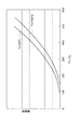
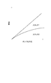
図4、図5は、本実施形態における第1の熱電素子100と、第2の熱電素子200それぞれの温度−発電特性を示す線図である。高温領域で使用される第1の熱電素子100は、高温端側の温度(Th)が高いほど、また、低温端側の温度(Tc)が低いほど発電量が増加する。そして、Thが同一の場合のTcの温度変化による発電量の差はThが高温であるほど大きくなる傾向がある。低温領域で使用される第2の熱電素子200においては、Thが同一の場合には、Tcが低いほど発電量が増加する点は第1の熱電素子100と共通するが、Tcが同一の場合には発電量が最大となるThが存在し、このピークを超えると、Th増大とともに発電量は急激に低下する。そして、このピークとなるThは、Tcが低いほど高温側に移行する。この場合も、Thが同一の場合のTcの温度変化による発電量の差は、Thが高温であるほど大きくなる傾向がある。
4 and 5 are diagrams showing temperature-power generation characteristics of the first
第1の熱電素子100と第2の熱電素子200の特性を配置位置の排ガスの温度特性に応じて適切なものとすることで、全体の発電特性を向上させることができる。なお、それぞれの熱電変換スタック1、2内部で異なる熱電材料を組み合わせてもよい。
By making the characteristics of the first
各熱電変換スタック1、2は電圧変換を行うDC−DCコンバータ50に電気的に接続されており、DC−DCコンバータ50は電力を蓄えるバッテリ51に電気的に接続されている。また、熱電変換スタック1、2には、冷却水を循環させる冷却系が接続されている。本実施形態においては、ラジエーター45から伸びるラインL1上に電動ポンプ70が配置されており、分岐式の流量制御弁72に接続されている。流量制御弁72からは、ラジエーター45へと戻るラインL2と、第2の熱電変換スタック2へと伸びるラインL3とが分岐されており、流量制御弁72によって各方向への流量比が調整される。そして、第2の熱電変換スタック2からの戻りラインL4はラインL2へ合流する。ラインL2の下流には、さらに、分岐式の流量制御弁71が配置されており、第1の熱電変換スタック1へと伸びるラインL5が分岐されている。そして、第1の熱電変換スタック1からの戻りラインL6はラインL2へ合流する。この冷却系は、図示していないエンジン40の冷却系と直列に接続されていてもよいし、並列に設けられていてもよい。
Each
排気管41の第1の熱電変換スタック1の上流側には、排ガスの温度、流量をそれぞれ測定する温度計61と、流量計62が配置されている。また、ラインL1上には、冷却水温度を測定する温度計63が配置されている。温度計61、63と流量計62の出力は制御ECU60に入力されており、制御ECU60は、電動ポンプ70と、各流量制御弁71、72およびDC−DCコンバータ50の作動を制御する。制御ECU60は、CPU、RAM、ROM等によって構成されており、単独で構成されていてもよいし、図示していない他の車両の制御系の一部として構成されていてもよい。
On the upstream side of the first
次に、本発明に係る熱電発電装置の動作を冷却系の制御動作と合わせて説明する。図6は冷却系の制御動作を示すフローチャートである。この制御は制御ECU60によってエンジン40が始動してから停止するまでの間、所定のタイミングで繰り返し実行される。
Next, the operation of the thermoelectric generator according to the present invention will be described together with the control operation of the cooling system. FIG. 6 is a flowchart showing the control operation of the cooling system. This control is repeatedly executed at a predetermined timing from when the
まず、ステップS1では、流量計62と温度計61、63の出力から、排気ガスの流量V、温度T1と、冷却水温度T2を読み込む。
First, read in step S1, the output of the
ここで、電動ポンプ70の消費電力をPp、各熱電変換スタック1、3の発電量をPs1、Ps2、回収電力量をPrとすると、Pr=Ps1+Ps2−Ppである。ここで、電動ポンプの消費電力は、冷却水量Vwの関数として表すことができる。一方、各熱電変換スタック1、3の発電量は、高温端側の温度Thと、低温端側の温度Tcに依存する。Th、Tcは、各熱電変換スタック1、3へ導入される排ガスの温度、流量と冷却水の温度、流量および当該スタック内の熱抵抗値から求めることができる。したがって、排気ガスの流量V、温度T1と、冷却水温度T2が既知であれば、Prを最大とする冷却水流量を求めることができる。本実施形態では、実際に熱計算を行うことは計算負荷を増大させることになるため、予め最上流部における排ガス温度、流量と冷却水温に対応する各流量制御弁71、72のバルブ開度を求めておいて、これをマップ形式で制御ECU60内に格納しておき、読み出されたV、T1、T2に応じて、このマップを参照して適切なバルブ開度を設定する(ステップS3)。
Here, if the power consumption of the
ステップS5では、設定したバルブ開度が実現されるよう、流量制御弁71、72に指示する。これにより、各熱電変換スタック1、3の冷却水流量を調整する。このとき、電動ポンプ70によってラジエーター45を循環させる流量そのものも調整すると好ましい。
In step S5, the
ここで、各熱電変換スタック1、3内部では、排気ガスが、ガイド板14(24)によって、集熱フィン13(23)のフィンの間へと導かれ、フィンに熱を伝える。この熱は、各フィンからその基部、絶縁材11(21)を通じて熱電変換モジュール10(20)の高温側端面へと伝えられる。これにより、高温側端面の温度は高くなる。
Here, in each
一方、熱電変換モジュール10(20)の低温側端面からは、絶縁材12(22)、冷却ケース15(25)を通じて冷却ケース15(25)の通路内を流れる冷却水へと熱が奪われている。このため、低温側端面の温度は低くなる。こうして、高温側端面と低温側端面との間に温度差が発生し、この温度差に応じてゼーベック効果により熱電変換モジュール10(20)内の熱電素子100(200)に電力が発生し、これをDC−DCコンバータ50により所定の電圧へ変換してバッテリ51へと蓄える。
On the other hand, heat is taken from the low temperature side end face of the thermoelectric conversion module 10 (20) to the cooling water flowing in the passage of the cooling case 15 (25) through the insulating material 12 (22) and the cooling case 15 (25). Yes. For this reason, the temperature of the low-temperature side end surface is lowered. Thus, a temperature difference is generated between the high temperature side end surface and the low temperature side end surface, and electric power is generated in the thermoelectric element 100 (200) in the thermoelectric conversion module 10 (20) by the Seebeck effect according to this temperature difference. Is converted into a predetermined voltage by the DC-
このとき、回収される電力が最大となるよう供給される冷却水の比率を変更しているため、過剰に冷却水を供給することがなく、効率よく排ガスからエネルギーを回収することができる。ここでは、排ガス、冷却水の状態量からマップ形式でバルブ開度を設定する例を説明したが、マップ形式のほかに、関数形式としてもよく、制御ECU60の計算能力に余裕がある場合には、計算により求めてもよい。
At this time, since the ratio of the cooling water supplied is changed so that the recovered electric power is maximized, the cooling water is not supplied excessively, and energy can be efficiently recovered from the exhaust gas. Here, an example in which the valve opening is set in a map format from the state quantities of exhaust gas and cooling water has been described. However, in addition to the map format, a function format may be used, and when the calculation capacity of the
また、ここでは、流量計62によって排気ガスの流量を測定したが、流速計を配置して、流量を推定してもよい。あるいは、エンジン40の運転条件(機関回転数、燃料噴射量等)を基にして流量を推定することもできる。
Although the flow rate of the exhaust gas is measured by the
図7は、本発明に係る熱電発電装置の第2の実施形態を示す概略構成図である。この実施形態の熱電発電装置は第1の実施形態の熱電発電装置(図1参照)と異なり、流量制御弁73をラインL1上に1つだけ設けて、この流量制御弁73により、第1の熱電変換スタック1へ供給される冷却水の流量と第2の熱電変換スタック2へ供給される冷却水の流量の比率を調整可能としている。
FIG. 7 is a schematic configuration diagram showing a second embodiment of the thermoelectric generator according to the present invention. Unlike the thermoelectric generator of the first embodiment (see FIG. 1), the thermoelectric generator of this embodiment is provided with only one flow
この実施形態では、流量比率を調整するために用いるバルブが流量制御弁73のみに限られる点を除いては、第1の実施形態とその動作は同一である。したがって、動作・制御の説明は省略する。
In this embodiment, the operation is the same as that of the first embodiment, except that the valve used for adjusting the flow rate ratio is limited to the
図8は、本発明に係る熱電発電装置の第3の実施形態を示す概略構成図である。この実施形態の熱電発電装置の冷却系は、第2の実施形態と基本的に同一である。ただし、本実施形態では、第1、第2の実施形態と異なり、各熱電変換スタック1、2の高温端側温度と低温端側温度を直接、温度計64a、64b、65a、65bにより測定している点が相違する。各温度計64a〜65bの出力は制御ECU60に入力されている。
FIG. 8 is a schematic configuration diagram showing a third embodiment of the thermoelectric generator according to the present invention. The cooling system of the thermoelectric generator of this embodiment is basically the same as that of the second embodiment. However, in this embodiment, unlike the first and second embodiments, the high temperature end side temperature and the low temperature end side temperature of each
この実施形態では、温度計64a、64b、65a、65bにより測定した各熱電変換スタック1、2の高温端側温度と低温端側温度から、その特性に基づいて得られる電力を直接求めることができる。この電力量を基にして冷却水流量を適切に制御することで、回収電力が最大となるよう制御を行う。この場合には、電動ポンプ70と流量制御弁73により冷却水量を変更した場合の回収電力量を予測して回収電力量が多くなるように電動ポンプ70と流量制御弁73を制御するフィードフォワード制御を行ってもよいし、電動ポンプ70と流量制御弁73をフィードバック調整してもよい。
In this embodiment, the electric power obtained based on the characteristics can be directly obtained from the high temperature end side temperature and the low temperature end side temperature of each
図9は、本発明に係る熱電発電装置の第4の実施形態を示す概略構成図である。この実施形態の熱電発電装置の冷却系は、第2の実施形態と基本的に同一である。ただし、本実施形態では、第1〜第3の実施形態と異なり、各熱電変換スタック1、2から取り出される電流値と起電圧とをそれぞれ電流計66a、66bと、電圧計67a、67bによって測定している点が相違する。各電流計66a、66bと、電圧計67a、67bの出力は制御ECU60に入力されている。
FIG. 9 is a schematic configuration diagram showing a fourth embodiment of a thermoelectric generator according to the present invention. The cooling system of the thermoelectric generator of this embodiment is basically the same as that of the second embodiment. However, in this embodiment, unlike the first to third embodiments, the current values and electromotive voltages taken from the
図10は、この場合の冷却制御動作の制御例を示すフローチャートである。ここでは、説明を簡単にするため、電動ポンプ70による循環水量が一定の場合を例に説明する。実際の制御においては、電動ポンプ70の循環水量を含めて制御してもよい。
FIG. 10 is a flowchart showing a control example of the cooling control operation in this case. Here, in order to simplify the description, a case where the amount of circulating water by the
まず、電流計66a、66bと、電圧計67a、67bの出力である各電流値、電圧値を読み込む(ステップS11)。次に、読み込んだ電流、電圧値と電動ポンプ70の作動電力から回収電力量Prを計算する(ステップS12)。
First, the current values and voltage values output from the
次に、算出した回収電力量Prと前回のタイムステップにおける回収電力量Proldとの差の絶対値がしきい値Pth未満であるか否かを判定する(ステップS13)。差の絶対値がしきい値Pth以上の場合には、ステップS14へと移行して、PrとProldとを比較する。 Next, it is determined whether or not the absolute value of the difference between the calculated recovered power amount Pr and the recovered power amount Prold at the previous time step is less than the threshold value Pth (step S13). If the absolute value of the difference is equal to or greater than the threshold value Pth, the process proceeds to step S14, and Pr and Prold are compared.
PrがProldより大きい場合には、流量制御弁の開度Aをi×Dだけ変更する(ステップS17)。ここで、Dは開度変更の変更ステップ量であり、iは1または−1の値をとり、前回の変更方向と同一に設定されている。つまり、前回のタイムステップで流量制御弁73の開度を増した結果、回収電力量が増大したと判定された場合には、流量制御弁73の開度をさらに増し、前回のタイムステップで流量制御弁73の開度を減らした結果、回収電力量が増大したと判定された場合には、流量制御弁73の開度をさらに減らす制御を行う。調整が終了したらステップS17へと移行して、変数Proldに現在の回収電力量Prの値を格納して処理を終了する。
If Pr is greater than Prold, the opening A of the flow control valve is changed by i × D (step S17). Here, D is a change step amount for changing the opening, i takes a value of 1 or -1, and is set to be the same as the previous change direction. That is, as a result of increasing the opening degree of the
ステップS14で、PrがProldより小さい場合には、iの符号を逆に変更し、流量制御弁の開度Aをi×Dだけ変更する(ステップS16)。つまり、前回のタイムステップで流量制御弁73の開度を増した結果、回収電力量が減少したと判定された場合には、流量制御弁73の開度を減らし、前回のタイムステップで流量制御弁73の開度を減らした結果、回収電力量が減少したと判定された場合には、流量制御弁73の開度を増やす制御を行う。なお、このフローでは、処理が収束しない場合がありうるため、ステップS16では、開度Aをi×D/2だけ変更してもよい。調整が終了したらステップS17へと移行して、変数Proldに現在の回収電力量Prの値を格納して処理を終了する。
If Pr is smaller than Prold in step S14, the sign of i is changed in reverse, and the opening degree A of the flow control valve is changed by i × D (step S16). That is, as a result of increasing the opening degree of the
ステップS13で差の絶対値がしきい値Pth未満の場合には、直接ステップS17へと移行して、変数Proldに現在の回収電力量Prの値を格納して処理を終了する。 If the absolute value of the difference is less than the threshold value Pth in step S13, the process proceeds directly to step S17, where the current value of the recovered power Pr is stored in the variable Prold, and the process ends.
このように、回収電力量が最大となるように流量制御弁73の作動を制御することで、排気ガスの有する熱エネルギーを効率よく電力として回収することができる。
In this way, by controlling the operation of the flow
図11は、本発明に係る熱電発電装置の第5の実施形態を示す概略構成図である。この実施形態では、冷却水配管上に流量制御弁は設けられていない。その代わりとして、第2の熱電変換スタック2の冷却ケース25の通水抵抗を利用している。
FIG. 11: is a schematic block diagram which shows 5th Embodiment of the thermoelectric power generating apparatus which concerns on this invention. In this embodiment, no flow control valve is provided on the cooling water pipe. Instead, the water flow resistance of the cooling
図12は、本実施形態の第2の熱電変換スタック2の断面構成を示す図(図11におけるXII−XII線断面図)であり、図13、図14は、ポンプ吐出圧の変化に伴う冷却ケース25内の通路255の断面形状変化を表す図である。
FIG. 12 is a diagram (cross-sectional view taken along line XII-XII in FIG. 11) of the second
冷却ケース25は、ともに断面が櫛歯状の上ケース251と下ケース250とをそれぞれの櫛歯が所定の隙間を有して噛み合わさるように組み合わせて構成されており、両者は抵抗調整バネ252によって結合されている。この隙間が冷却水が流れる通路255となる。なお、バネ252に代えて、ゴム、樹脂等の弾性体や空気バネ、液体バネ等を用いてもよい。
The cooling
電動ポンプ70の吐出圧が低い状態では、抵抗調整バネ252が上ケース251と下ケース250を接近させようと作用する力が、通路255内を流れる冷却水が通路255の断面積を拡げようとする力に勝るため、通路255の断面は図13に示されるように狭い状態に維持される。この結果、第2の熱電変換スタック2へと供給される冷却水の比率は低くなる。
In a state where the discharge pressure of the
電動ポンプ70の吐出圧を高くすると、通路255内を流れる冷却水が通路255の断面積を拡げようとする力が抵抗調整バネ252が上ケース251と下ケース250を接近させようと作用する力を上回り、両者が釣り合うまで通路255の断面積は拡大される(図14参照)。この結果、第2の熱電変換スタック2へと供給される冷却水の比率は高くなる。
When the discharge pressure of the
つまり、電動ポンプ70の吐出圧を変更することで、第1、第2の熱電変換スタック1、2へと供給される冷却水の比率を変更することができる。この実施形態では、流量制御弁が不要となるため、冷却水配管の構造を簡素化することができる。
That is, the ratio of the cooling water supplied to the first and second
抵抗調整バネ252のバネ定数を高くすると、電動ポンプ70の吐出圧を上げても通路255の断面積が変化しにくくなる。第1の熱電変換スタック1と第2の熱電変換スタック2へ供給する冷却水の流量配分に応じてバネ定数を適宜設定するとよい。また、バネ定数が非線形的に変化する弾性体を用いることも可能である。
When the spring constant of the
また、第1の熱電変換スタック1にも同様の冷却ケースを採用してもよい。例えば、熱電変換スタック2側の抵抗調整バネ252のバネ定数を熱電変換スタック1側の抵抗調整バネのバネ定数より小さくしておくと、ポンプ吐出圧に応じた各熱電変換スタック1、2への供給冷却水量を図15に示されるように調整することができる。これは、熱電変換スタック2側は、熱電変換スタック1より低い吐出圧で冷却水の通路255が全開状態となり、その後は吐出圧を増大させても通路255の断面積が増大しなくなるためである。
A similar cooling case may be employed for the first
図16は、本発明に係る熱電発電装置の第6の実施形態を示す概略構成図である。この実施形態は、第2の熱電変換スタック2からラジエーター45へ戻る冷却水配管のラインL2上に、切替弁74を配置して、第1の熱電変換スタック1へと冷却水を導入するラインL5を設け、第1の熱電変換スタック1からの冷却水返送ラインL6をラインL2と合流させている。また、排気浄化触媒3の触媒温度を検出する温度計68を設け、各熱電変換スタック1、2の熱電変換モジュール10、20の温度を測定する温度計64a、65aの出力とともに制御ECU60へと入力している。
FIG. 16: is a schematic block diagram which shows 6th Embodiment of the thermoelectric power generator which concerns on this invention. In this embodiment, a switching valve 74 is arranged on a line L2 of the cooling water pipe that returns from the second
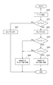
図17は、本実施形態の冷却制御を示すフローチャートである。この制御も制御ECU60によって、エンジン40が始動してから停止するまでの間、所定のタイミングで繰り返し実行される。
FIG. 17 is a flowchart showing the cooling control of this embodiment. This control is also repeatedly executed by the
まず、温度計64a、65a、68の出力を読み込むことで、各熱電変換スタック1、2のモジュール温度T1、T3と、排気浄化触媒3の触媒温度T2を読み込む(ステップS20)。
First, by reading the output of the
次に、第2の熱電変換スタック2のモジュール温度T3が、単独運転時に電動ポンプ70の作動電力を上回る発電量を確保しうるしきい値温度Te−2を超えているか否かを判定する(ステップS21)。T3がTe−2以下の場合には、第2の熱電変換スタック2への冷却水供給を行っても、第2の熱電変換スタック2で得られる電力が電動ポンプ70の作動電力を下回り、実際には電力を回収できない可能性があると判定して、ステップS27へと移行し、電動ポンプ70の作動を停止させて処理を終了する。
Next, it is determined second module temperature T 3 of the
ステップS21で、T3がTe−2を上回っている場合には、ステップS22へと移行して電動ポンプ70を作動させ、第1の熱電変換スタック1のモジュール温度T1が、第1の熱電変換スタック1および第2の熱電変換スタック2双方の運転時に電動ポンプ70の作動電力を上回る発電量を確保しうるしきい値温度Te−1を超えているか否かを判定する(ステップS23)。T1がTe−1を超えている場合には、さらに、触媒温度T2が活性温度TCATを超えているか否かを判定する(ステップS24)。
In step S21, if the T 3 is higher than the T e-2 activates the
T2がTCATを超えている場合には、排気浄化触媒3が活性化されており、第1の熱電変換スタック1を作動させても、排気浄化触媒3は良好に作動すると判定して、ステップS25へと移行し、切替弁74を第1の熱電変換スタック1側へと切り替えて、第1の熱電変換スタック1へと冷却水を供給する。
When T 2 exceeds T CAT , it is determined that the
一方、ステップS23で、T1がTe−1以下と判定された場合には、排ガス温度が低く、第1の熱電変換スタック1を作動させると、下流側へと流れる排ガス温度が低下して、第2の熱電変換スタック2で発生する電力量も低下して、第2の熱電変換スタック2のみを作動させた場合に比較して、発生電力量が減り、電動ポンプ70の作動電力を確保できないと判定して、ステップS26へと移行して、切替弁74をラジエーター45側へと切り替えて、第1の熱電変換スタック1の作動を停止する。
また、ステップS24で、T2がTCAT以下と判定された場合には、第1の熱電変換スタック1を作動させると、排気浄化触媒3へと流れ込む排ガス温度が低下するため、その暖機に時間を要し、その間エミッションが悪化するおそれがあると判定し、同じくステップS26へと移行して、切替弁74をラジエーター45側へと切り替えて、第1の熱電変換スタック1の作動を停止する。
On the other hand, in step S23, when T 1 is is determined that T e-1 or less, low exhaust gas temperature, when actuated first
Further, in step S24, if the T 2 is determined to be less T CAT, when actuating the first
例えば、冷間始動時の初期の時点では、第1の熱電変換スタック1を作動させると、排気浄化触媒3へ流入する排気ガス温度が低下してしまい、排気浄化触媒3の暖機を妨げる結果になる。また、第2の熱電変換スタック2を作動させても、得られる電力が電動ポンプ70の作動電力を下回ってしまい、実際の回収電力がマイナスになってしまう。本実施形態では、このように、第2の熱電変換スタック2のモジュール温度が低い条件下では、、電動ポンプ70を停止させて排気ガスからの熱回収を行わない。このため、排気浄化触媒3を速やかに昇温させて暖機を行うことができる。
For example, when the first
始動後時間が経過して、第2の熱電変換スタック2が昇温されると、その作動によって得られる電力が電動ポンプ70の作動電力を上回るため、電動ポンプ70の作動を開始する。一方、排気浄化触媒3の暖機が完了しておらず、触媒温度が低い場合には、第1の熱電変換スタック1を作動させることは排気浄化触媒3の暖機を妨げる結果になるため、切替弁74をラジエーター45側へと切り替えることで、第1の熱電変換スタック1は作動させず、排気浄化触媒3の昇温を優先する。
When time elapses after the start and the temperature of the second
排気浄化触媒3の暖機後、低速または低負荷領域では、エンジン40からの排ガス流量が少なく、第1の熱電変換スタック1の温度は低くなる。この状態で、第1の熱電変換スタック1を作動させても、発電効率が低く、通水抵抗が増大して電動ポンプ70の負荷が増大し、システム全体としての発電効率が低下してしまう。また、排気浄化触媒3へ流入する排ガス温度が低下することで、排気浄化触媒3が冷却され、その浄化性能が低下するおそれがある。そこで、このような場合は、切替弁74をラジエーター45側へと切り替えることで、第1の熱電変換スタック1を作動させず、第2の熱電変換スタック2のみによる発電を行う。
After the
中高速または中高負荷領域では、エンジン40からの排ガス流量も増大し、第1の熱電変換スタック1の温度は高く、十分な発電効率が得られるとともに、排気浄化触媒3へ流入する排ガス温度も浄化性能を発揮できる温度に維持できる。そこで、切替弁74を第1の熱電変換スタック1側へと切り替えることで、第1、第2の熱電変換スタック1、2双方を作動させて、熱回収を行う。
In the middle / high speed or middle / high load region, the exhaust gas flow rate from the
このような制御を行うことで、排気浄化触媒の暖機および確実な作動と効率のよい熱回収とを両立させ、エミッションの悪化を抑制し、環境負荷を軽減することができる。 By performing such control, it is possible to achieve both warm-up and reliable operation of the exhaust purification catalyst and efficient heat recovery, suppress emission deterioration, and reduce the environmental load.
以上説明した各実施形態は、組み合わせて使用することが可能である。例えば、第1〜第5の実施形態において、触媒温度を参照して、第1の熱電変換スタック1への冷却水量を調整してもよい。この場合を含めて、冷却水流量または比率の調整には、一方のスタックへの冷却水の供給を完全に停止することも含まれている。また、第6の実施形態では、モジュール温度を参照して各モジュールの動作状態に応じた制御を行ったが、第1の実施形態のように排気ガスの状態量を参照して制御を行ったり、第3の実施形態に示されるように各スタックの発電量を参照して制御を行ってもよい。
Each embodiment described above can be used in combination. For example, in the first to fifth embodiments, the amount of cooling water to the first
以上の説明では、第1および第2の熱電変換スタック1、2間の冷却水供給比率を調整する実施形態について説明したが、3つ以上の熱電変換スタック間で冷却水供給比率を調整する場合も本発明の範囲に含まれる。例えば、第3の熱電変換スタックを有する場合、この熱電変換スタックは、第1、第2の熱電変換スタックの中間に配置されてもいいし、第1または第2の熱電変換スタックと並列に配置されていてもよい。
In the above description, the embodiment for adjusting the cooling water supply ratio between the first and second
また、以上の説明では、車両のエンジン40の排気系に搭載される形態を説明してきたが、本発明はこれに限られるものではなく、エンジン、ボイラー等の各種燃焼機器の排気系に接続される熱電発電装置のほか、温排水等から熱回収を行う熱電発電装置にも好適に適用できる。
In the above description, the form mounted on the exhaust system of the
さらに、以上の説明では、冷媒として、冷却水を用いる場合を例示したが、空冷式、油冷式の場合や、フロンガス等の相変化媒体を用いてもよい。 Furthermore, in the above description, the case where cooling water is used as the refrigerant is illustrated, but an air cooling type, an oil cooling type, or a phase change medium such as Freon gas may be used.
1…第1の熱電変換スタック、2…第2の熱電変換スタック、3…排気浄化触媒、10…第1の熱電変換モジュール、11、12、21、22…絶縁材、13、23…集熱フィン、14、24…ガイド板、15、25…冷却ケース、16、26…固定部材、20…第2の熱電変換モジュール、40…エンジン、41…排気管、45…ラジエーター、50…DC−DCコンバータ、51…バッテリ、60…制御ECU、61、63、64a、64b、65a、65b、68…温度計、62…流量計、66a、66b…電流計、67a、67b…電圧計、70…電動ポンプ、71〜73…流量制御弁、74…切替弁、100、200…熱電素子、101、102、201、202…半導体、103、104、203、204…電極、250…下ケース、251…上ケース、252…抵抗調整バネ、255…通路。
DESCRIPTION OF
Claims (5)
前記第1の熱電変換モジュールと前記第2の熱電変換モジュールに供給する冷媒の比率を変更する比率変更手段を備えていることを特徴とする熱電発電装置。 A first thermoelectric conversion module having a thermoelectric element disposed upstream of the heat medium flow path and generating an electromotive force due to a temperature difference between the heat medium flowing through the heat medium flow path and the supplied refrigerant; and the heat medium flow A thermoelectric generator comprising a second thermoelectric conversion module that is disposed on the downstream side of a path and has a thermoelectric element that generates an electromotive force due to a temperature difference between a heat medium flowing through the heat medium flow path and a supplied refrigerant. ,
A thermoelectric generator comprising a ratio changing means for changing a ratio of refrigerant supplied to the first thermoelectric conversion module and the second thermoelectric conversion module.
Priority Applications (1)
| Application Number | Priority Date | Filing Date | Title |
|---|---|---|---|
| JP2004109294A JP2005295725A (en) | 2004-04-01 | 2004-04-01 | Thermoelectric generator |
Applications Claiming Priority (1)
| Application Number | Priority Date | Filing Date | Title |
|---|---|---|---|
| JP2004109294A JP2005295725A (en) | 2004-04-01 | 2004-04-01 | Thermoelectric generator |
Publications (1)
| Publication Number | Publication Date |
|---|---|
| JP2005295725A true JP2005295725A (en) | 2005-10-20 |
Family
ID=35328045
Family Applications (1)
| Application Number | Title | Priority Date | Filing Date |
|---|---|---|---|
| JP2004109294A Pending JP2005295725A (en) | 2004-04-01 | 2004-04-01 | Thermoelectric generator |
Country Status (1)
| Country | Link |
|---|---|
| JP (1) | JP2005295725A (en) |
Cited By (14)
| Publication number | Priority date | Publication date | Assignee | Title |
|---|---|---|---|---|
| JP2008167626A (en) * | 2007-01-04 | 2008-07-17 | Toyota Motor Corp | Thermoelectric generator |
| WO2010112961A1 (en) * | 2009-03-31 | 2010-10-07 | Renault Trucks | Energy recovery system for an internal combustion engine arrangement, comprising thermoelectric devices |
| JP2011165976A (en) * | 2010-02-10 | 2011-08-25 | Toshiba Corp | Thermoelectric converter and thermoelectric conversion method |
| JP2011211764A (en) * | 2010-03-29 | 2011-10-20 | Panasonic Corp | Thermoelectric converter |
| JP2012197073A (en) * | 2011-03-18 | 2012-10-18 | Agustawestland Spa | Aircraft capable of hovering |
| JP2014051891A (en) * | 2012-09-05 | 2014-03-20 | Toyota Motor Corp | Thermoelectric generator |
| JP2014109256A (en) * | 2012-12-04 | 2014-06-12 | Toyota Motor Corp | Thermoelectric generator |
| JP2014216486A (en) * | 2013-04-25 | 2014-11-17 | 株式会社東芝 | Thermoelectric power generation system and thermoelectric power generation method |
| JP2015520836A (en) * | 2012-04-13 | 2015-07-23 | エーバーシュペッヒャー・エグゾースト・テクノロジー・ゲーエムベーハー・ウント・コンパニー・カーゲー | Heat exchanger with thermoelectric generator |
| JP2016158424A (en) * | 2015-02-25 | 2016-09-01 | 千代田化工建設株式会社 | Power generation system |
| JP2017107925A (en) * | 2015-12-08 | 2017-06-15 | 日立化成株式会社 | Thermoelectric conversion module and manufacturing method thereof |
| WO2018173853A1 (en) * | 2017-03-21 | 2018-09-27 | 日本電気株式会社 | Heat exchange device, heat exchange system, and heat exchange method |
| KR20200077823A (en) * | 2018-12-21 | 2020-07-01 | 주식회사 아프로스 | Thermoelectric Generator for supplying Power Source of IoT Smart Sensor |
| CN115592911A (en) * | 2021-07-08 | 2023-01-13 | 汉达精密电子(昆山)有限公司(Cn) | Thermoelectric conversion method and equipment for rapid cooling and heating equipment of die |
-
2004
- 2004-04-01 JP JP2004109294A patent/JP2005295725A/en active Pending
Cited By (21)
| Publication number | Priority date | Publication date | Assignee | Title |
|---|---|---|---|---|
| JP2008167626A (en) * | 2007-01-04 | 2008-07-17 | Toyota Motor Corp | Thermoelectric generator |
| WO2010112961A1 (en) * | 2009-03-31 | 2010-10-07 | Renault Trucks | Energy recovery system for an internal combustion engine arrangement, comprising thermoelectric devices |
| CN102365437A (en) * | 2009-03-31 | 2012-02-29 | 雷诺卡车公司 | Energy recovery system for an internal combustion engine arrangement, comprising thermoelectric devices |
| JP2012522176A (en) * | 2009-03-31 | 2012-09-20 | ルノー・トラックス | Energy recovery system for an internal combustion engine device comprising a thermoelectric device |
| JP2011165976A (en) * | 2010-02-10 | 2011-08-25 | Toshiba Corp | Thermoelectric converter and thermoelectric conversion method |
| JP2011211764A (en) * | 2010-03-29 | 2011-10-20 | Panasonic Corp | Thermoelectric converter |
| JP2012197073A (en) * | 2011-03-18 | 2012-10-18 | Agustawestland Spa | Aircraft capable of hovering |
| JP2015520836A (en) * | 2012-04-13 | 2015-07-23 | エーバーシュペッヒャー・エグゾースト・テクノロジー・ゲーエムベーハー・ウント・コンパニー・カーゲー | Heat exchanger with thermoelectric generator |
| JP2014051891A (en) * | 2012-09-05 | 2014-03-20 | Toyota Motor Corp | Thermoelectric generator |
| JP2014109256A (en) * | 2012-12-04 | 2014-06-12 | Toyota Motor Corp | Thermoelectric generator |
| JP2014216486A (en) * | 2013-04-25 | 2014-11-17 | 株式会社東芝 | Thermoelectric power generation system and thermoelectric power generation method |
| JP2016158424A (en) * | 2015-02-25 | 2016-09-01 | 千代田化工建設株式会社 | Power generation system |
| WO2016136246A1 (en) * | 2015-02-25 | 2016-09-01 | 千代田化工建設株式会社 | Power generation system |
| JP2017107925A (en) * | 2015-12-08 | 2017-06-15 | 日立化成株式会社 | Thermoelectric conversion module and manufacturing method thereof |
| WO2018173853A1 (en) * | 2017-03-21 | 2018-09-27 | 日本電気株式会社 | Heat exchange device, heat exchange system, and heat exchange method |
| JPWO2018173853A1 (en) * | 2017-03-21 | 2020-05-14 | 日本電気株式会社 | Heat exchange device, heat exchange system, and heat exchange method |
| JP7010283B2 (en) | 2017-03-21 | 2022-01-26 | 日本電気株式会社 | Heat exchanger, heat exchange system and heat exchange method |
| US11411156B2 (en) | 2017-03-21 | 2022-08-09 | Nec Corporation | Heat exchange device, heat exchange system, and heat exchange method |
| KR20200077823A (en) * | 2018-12-21 | 2020-07-01 | 주식회사 아프로스 | Thermoelectric Generator for supplying Power Source of IoT Smart Sensor |
| KR102180178B1 (en) * | 2018-12-21 | 2020-11-18 | 주식회사 아프로스 | Thermoelectric Generator for supplying Power Source of IoT Smart Sensor |
| CN115592911A (en) * | 2021-07-08 | 2023-01-13 | 汉达精密电子(昆山)有限公司(Cn) | Thermoelectric conversion method and equipment for rapid cooling and heating equipment of die |
Similar Documents
| Publication | Publication Date | Title |
|---|---|---|
| JP2005295725A (en) | Thermoelectric generator | |
| JP2006214350A (en) | Thermoelectric generator | |
| EP2811142B1 (en) | Thermoelectric generator | |
| CN101213679B (en) | Thermoelectric Generators for Variable Thermal Power Sources | |
| KR100869322B1 (en) | Thermoelectric Generation System Using Exhaust Heat | |
| EP1564822B1 (en) | Electric power generating apparatus and its control method | |
| JP2008274790A (en) | Waste heat recovery device | |
| JP2005137188A (en) | Exhaust gas purification device | |
| US10454011B2 (en) | Malfunction detection device for power generator | |
| KR20100120339A (en) | Thermoelectric generation system for withdrawing heat of exhaust gas | |
| KR20140125628A (en) | Automotive generator module using the waste heat and sub charging system for Automotive battery with the same | |
| KR101207815B1 (en) | Thermoelectric generating system and control methode thereof | |
| JP2000352313A (en) | Automotive waste heat power generator | |
| KR101309554B1 (en) | Thermoelectric generation for independent power supply device use industrial waste heat | |
| JP2004140202A (en) | Thermoelectric conversion system | |
| JP4328803B2 (en) | Electricity cogeneration using the Seebeck effect inside a fuel cell | |
| JP2005269713A (en) | Thermoelectric generator | |
| KR102142384B1 (en) | An Thermoelectric Generation Apparatus and Control method thereof | |
| JP2005051934A (en) | Thermoelectric power generation system | |
| JP2008045409A (en) | Exhaust gas purification system | |
| KR102062630B1 (en) | Thermoelectric Generation Module Adaptive to Temperature Condition | |
| JP4935361B2 (en) | Thermoelectric generator | |
| JP5318667B2 (en) | Engine exhaust heat recovery device | |
| JP2005051952A (en) | Power generator | |
| JP4244833B2 (en) | Waste heat recovery device |