JP2005295626A - Generator drive control device - Google Patents
Generator drive control device Download PDFInfo
- Publication number
- JP2005295626A JP2005295626A JP2004104161A JP2004104161A JP2005295626A JP 2005295626 A JP2005295626 A JP 2005295626A JP 2004104161 A JP2004104161 A JP 2004104161A JP 2004104161 A JP2004104161 A JP 2004104161A JP 2005295626 A JP2005295626 A JP 2005295626A
- Authority
- JP
- Japan
- Prior art keywords
- generator
- current
- voltage
- mode
- drive control
- Prior art date
- Legal status (The legal status is an assumption and is not a legal conclusion. Google has not performed a legal analysis and makes no representation as to the accuracy of the status listed.)
- Pending
Links
Images
Landscapes
- Control Of Eletrric Generators (AREA)
Abstract
【課題】 小型化、高信頼性を実現しつつ、発電出力についての種々の制御を可能とする、発電機の駆動制御装置を提供する。
【解決手段】 駆動制御装置20は永久磁石回転子(11)と固定子(13)を含む発電機(10)を位置センサレスで駆動し、複数の整流ダイオードと複数のスイッチング素子を含み、発電機で発電された交流電圧を直流電圧に変換するインバータ(21)と、インバータのスイッチング素子のオン・オフを制御して発電出力を制御する制御部(25、27)とを備える。制御部(25、27)は固定子巻線の誘起電圧に基づいて回転子位置を検出し、検出した回転子位置に応じて固定子巻線電流の電流進角及び電流振幅を制御することにより発電出力を制御する。
【選択図】図1
PROBLEM TO BE SOLVED: To provide a drive control device for a generator capable of various control of power generation output while realizing miniaturization and high reliability.
A drive control device 20 drives a generator (10) including a permanent magnet rotor (11) and a stator (13) without a position sensor, includes a plurality of rectifier diodes and a plurality of switching elements, and includes a generator. And an inverter (21) that converts the AC voltage generated in step 1 into a DC voltage, and a controller (25, 27) that controls on / off of the switching elements of the inverter to control the power generation output. The control units (25, 27) detect the rotor position based on the induced voltage of the stator winding, and control the current advance angle and current amplitude of the stator winding current according to the detected rotor position. Control power generation output.
[Selection] Figure 1
Description
本発明は、永久磁石が埋込まれた回転子を用いた発電機の位置センサレス駆動を行う、発電機の駆動制御装置に関する。 The present invention relates to a generator drive control device that performs position sensorless driving of a generator using a rotor in which a permanent magnet is embedded.
従来より、発電機に対する制御システムが種々考案されている(例えば特許文献1、特許文献2参照)。
Conventionally, various control systems for generators have been devised (see, for example,
特許文献1に記載の発電制御システムは、回転駆動源に連結した発電機と、発電機で発電された交流電圧を直流電圧に整流する整流回路と、整流回路からの直流電圧を所望の電圧に変圧するDC−DCコンバータと、DC−DCコンバータからの出力を所望の駆動電力に変換するインバータとを備えている。また、特許文献1の発電制御システムでは、発電機の回転子の位置は発電機内部に組み込まれた位置センサを用いて検出されている。
A power generation control system described in
特許文献2は、インバータを用いて位置センサレスで同期発電機を駆動する発電機制御システムを開示している。
特許文献1に記載の発電制御システムでは、電圧変動を吸収するためのDC−DCコンバータを備えているが、DC−DCコンバータは回転変化による装置の大型化、効率の低下を招くという問題がある。また、位置センサを発電機内部に組み込んでいるため、発電機が大型化し、位置センサ分だけ、信頼性の低下、製造コストの増加を招くという問題もある。
The power generation control system described in
また、特許文献2は、高回転領域において対応可能なセンサレス同期発電機制御システムを提供することを目的としたものであるため、主として高速動作時における回転子の磁極位置情報の取得方法について開示しているのみであり、発電出力に対する電圧、電流等の制御について具体的な開示はない。
Further, since
本発明は上記課題に鑑みてなされたものであり、小型化、高信頼性を実現しつつ、発電出力についての種々の制御を可能とする、発電機の駆動制御装置を提供することを目的とする。 The present invention has been made in view of the above problems, and an object of the present invention is to provide a drive control device for a generator that enables various controls on power generation output while realizing miniaturization and high reliability. To do.
本発明に係る駆動制御装置は、永久磁石が埋込まれた回転子と固定子を含む発電機を位置センサレス方式で駆動する装置である。駆動制御装置は、複数の整流ダイオードと複数のスイッチング素子を含み、発電機で発電された交流電力を直流電力に変換する発電用インバータと、発電用インバータのスイッチング素子のオン・オフを制御して発電出力を制御する制御手段とを備える。制御手段は固定子巻線の誘起電圧に基づいて回転子位置を検出し、その検出した回転子位置に応じて固定子巻線電流の電流進角及び電流振幅の少なくともいずれかを制御することにより、出力電圧及び出力電流の少なくともいずれかを制御する。 The drive control device according to the present invention is a device that drives a generator including a rotor and a stator embedded with permanent magnets in a position sensorless manner. The drive control device includes a plurality of rectifier diodes and a plurality of switching elements, and controls on / off of a power generation inverter that converts AC power generated by the generator into DC power, and a switching element of the power generation inverter. Control means for controlling the power generation output. The control means detects the rotor position based on the induced voltage of the stator winding, and controls at least one of the current advance angle and current amplitude of the stator winding current according to the detected rotor position. , Controlling at least one of the output voltage and the output current.
制御手段は、発電機の始動時に用いる動作モードである始動モードと、定常運転状態において発電機の固定子巻線の誘起電圧に基づいて回転子位置を検出しながら発電機を運転する通常動作モードとを有してもよい。 The control means includes a start mode which is an operation mode used when starting the generator, and a normal operation mode in which the generator is operated while detecting the rotor position based on the induced voltage of the stator winding of the generator in a steady operation state. You may have.
制御手段は、始動モードにおいて無負荷時の誘起電圧を検出し、その検出した誘起電圧に基づいて初期位置を検出し、初期位置検出後に通常動作モードに移行するようにしてもよい。 The control means may detect an induced voltage at no load in the start mode, detect an initial position based on the detected induced voltage, and shift to the normal operation mode after detecting the initial position.
制御手段は、始動モードにおいて無負荷時の誘起電圧を検出し、検出した誘起電圧に基づいて回転数を検出し、回転数検出後に通常動作モードに移行するようにしてもよい。 The control means may detect the induced voltage when there is no load in the start mode, detect the rotational speed based on the detected induced voltage, and shift to the normal operation mode after detecting the rotational speed.
制御手段は、始動モードから通常モードに移行する間、電流振幅を略ゼロに制御して、発電を抑制してもよい。または、電流進角を制御して発電を抑制してもよい。 The control means may suppress power generation by controlling the current amplitude to be substantially zero during the transition from the start mode to the normal mode. Alternatively, power generation may be suppressed by controlling the current advance angle.
また、制御手段は、インバータに流れる電流またはインバータの出力電圧を検出し、過電流または過電圧が検出されたときに、インバータを発電機または負荷から切り離してもよい。 The control means may detect the current flowing through the inverter or the output voltage of the inverter, and disconnect the inverter from the generator or the load when an overcurrent or overvoltage is detected.
また、制御手段は発電機の故障を検出し、故障が検出されたときに発電を停止させるようにしてもよい。発電機の故障は、発電機の回転速度ムラ及び電流波形のうちの少なくともいずれかで検出できる。 Further, the control means may detect a failure of the generator and stop the power generation when the failure is detected. The failure of the generator can be detected by at least one of the rotational speed unevenness of the generator and the current waveform.
発電機は風力を動力源として発電してもよい。 The generator may generate power using wind power as a power source.
また、制御手段は、発電機の始動時において発電機を力行動作させ、発電機の始動時の回転を補助するようにしてもよい。 Further, the control means may power-operate the generator at the start of the generator to assist the rotation at the start of the generator.
また、制御手段は、発電機の運転中において、発電機の回転数を検出し、回転数が所定値以下になったときは、発電機を力行動作させて発電機の回転数を所定値以上に維持するようにしてもよい。 In addition, the control means detects the number of revolutions of the generator during operation of the generator, and when the number of revolutions becomes a predetermined value or less, the control unit operates the power generator so that the number of revolutions of the generator exceeds the predetermined value. You may make it maintain to.
また、制御手段は以下のモードの中の少なくとも1つを有するようにしてもよい。
−固定子巻線電流の電流進角及び電流振幅を制御し、出力電圧を略一定に制御する定電圧制御モード
−固定子巻線電流の電流進角及び電流振幅を制御し、出力電流を略一定に制御する定電流制御モード
−固定子巻線電流の電流進角及び電流振幅を制御し、出力電力を略一定に制御する定電力制御モード
−固定子巻線電流の電流進角及び電流振幅を制御し、前記発電機の回転数を略一定に制御する回転数制御モード。
Further, the control means may have at least one of the following modes.
-Constant voltage control mode that controls the current advance angle and current amplitude of the stator winding current and controls the output voltage to be substantially constant-Controls the current advance angle and current amplitude of the stator winding current, and substantially reduces the output current. Constant current control mode for constant control-Constant power control mode for controlling the current advance angle and current amplitude of the stator winding current to control the output power substantially constant-Current advance angle and current amplitude of the stator winding current And a rotational speed control mode for controlling the rotational speed of the generator to be substantially constant.
本発明によれば、小型化、高信頼性を実現しつつ、発電出力についての種々の制御を可能とする、発電機の駆動制御装置を実現できる。 ADVANTAGE OF THE INVENTION According to this invention, the drive control apparatus of a generator which enables various control about electric power generation output, implement | achieving size reduction and high reliability is realizable.
以下、添付の図面を参照し、本発明に係る発電機の駆動制御装置の実施形態について説明する。 DESCRIPTION OF EMBODIMENTS Hereinafter, an embodiment of a generator drive control device according to the present invention will be described with reference to the accompanying drawings.
1.発電機の駆動制御装置の構成
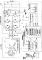
図1は本発明に係る発電機の駆動制御装置を用いた発電システムの構成を示した図である。発電システムは、発電機10と、駆動制御装置20と、バッテリ30とを含む。発電機10は永久磁石が埋込まれた回転子11と固定子巻線13を含む。駆動制御装置20は発電機10を制御する装置であって、遮断機41を介して発電機10と接続される。駆動制御装置20はバッテリ30に接続される。バッテリ30には負荷50が接続される。
1. 1. Configuration of Generator Drive Control Device FIG. 1 is a diagram showing the configuration of a power generation system using the generator drive control device according to the present invention. The power generation system includes a
駆動制御装置20はインバータ21と、PWM電圧制御部23と、モータ制御部25と、発電制御部27と、回転子位置検出部29と、回転数検出部31と、電圧検出部33と、電力検出部35と、遮断機42と、各種センサ43、44、45と、平滑コンデンサ46とを備える。
The
インバータ21はダイオードが直列に接続されてなるハーフブリッジ回路を3相分有し、各ダイオードには並列にトランジスタやIGBT、MOSからなるスイッチング素子が接続されている。インバータ21は、主として発電機10を発動動作させるよう駆動する発電用のインバータであるが、必要に応じて発電機10を電動機動作させるよう駆動することもできる。インバータ21のダイオードブリッジは整流機能を有し、発電された交流電圧を直流電圧に変換する。このダイオードの機能だけでは、発電電圧の大きさの制御は不可能であるが、本実施形態では、インバータ21における各スイッチング素子のオン・オフを適宜制御することにより、発電機10に適宜電流を回生させ、発電機10の固定子巻線のインダクタンスを利用し、発電システムの出力電圧の制御、出力電流等の制御を可能としている。
The
回転子位置検出部29は、電流センサ43、44の出力、及びモータパラメータに基づいて回転子位置θを検出する。回転数検出部31は回転子位置検出部29からの出力に基づいて回転数nを検出する。
The
モータ制御部25は発電機10をモータとして利用する際すなわち力行動作させる際の制御を行う。発電制御部27は発電機10の発電動作を制御する手段であり、電流振幅制御、電流進角(位相)制御、回転数制御、始動制御、保護制御の各制御を実行する。モータ制御部25及び発電制御部27は、インバータ21から出力される電流Idc、インバータ21の直流出力電圧Vdc、インバータ21の出力電力Wdcと、位相θ、回転数n、発電機10の誘起電圧v、発電機10の巻線電流iとに基づいて、PWM電圧制御部23に制御信号Vpwmを出力する。
The
PWM電圧制御部23はモータ制御部25または発電制御部27からの制御信号Vpwmを受けて、インバータ21の各スイッチング素子の動作を制御するためのパルス幅変調されたゲート信号を生成する。電圧検出部33は平滑コンデンサ46の電圧すなわちインバータ21の直流出力電圧Vdcを検出する。電力検出部35は、電流センサ45により検出されたインバータ21電流Idcと、電圧検出部33による検出電圧Vdcとにより、インバータ21の直流出力電力Wdcを検出する。
The PWM
以上のように構成される駆動制御装置20は、発電機10を発電動作させる時は、外部より、出力電圧、出力電力、出力電流、回転数及び効率に関する指令を入力し、それらの指令に応じてインバータ21の制御を行う。また、駆動制御装置20は、発電機10をモータ動作(力行動作)させる時は、回転数、電力、電流に関する指令を外部より入力し、インバータ21の制御を行う。
The
2.発電機の駆動制御装置の応用例
ここで、図1に示す駆動制御装置20を用いた種々の発電装置の応用例を示す。
2. Application Examples of Generator Drive Control Device Here, application examples of various power generation devices using the
(応用例1)
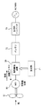
図2は、図1に示す駆動制御装置20を利用した風力発電装置の構成例を示した図である。風力発電装置は、プロペラ61に連結された発電機60と、発電機60の発電動作、モータ動作を制御する駆動制御装置20と、発電機で発電された電力を蓄積するバッテリ72と、バッテリ72に蓄積された電力を所定の交流電圧に変換する出力用インバータ73を備える。発電時においては、プロペラ61で受けた風力を発電機60にて電気エネルギに変換し、その電気エネルギをバッテリ72に蓄積する。出力用インバータ73は、バッテリ72に蓄積された直流電圧を所望の交流電圧に変換して供給する。駆動制御装置20に対しては設定器71から指令が入力される。駆動制御装置20は、内部に含むインバータにより発電機60の電流、電圧、進角(位相)等を適宜制御し、発電機60の発電動作またはモータ動作を制御することにより、出力電圧、出力電流の制御を行う。また、風力による発電機60の始動を補助するために定期的に、発電機60をモータとして起動し、プロペラ61の回転動作を補助する。
(Application 1)
FIG. 2 is a diagram illustrating a configuration example of a wind turbine generator that uses the
(応用例2)
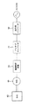
図3は、図1に示す駆動制御装置20を利用した車両用発電装置の構成例を示した図である。車両用発電装置は、エンジン63に連結した発電機60と、発電機60を駆動制御する駆動制御装置20と、発電した電力を蓄積するキャパシタ(またはバッテリ)81と、蓄積した電力を所望の電力に変換する出力用インバータ82とを備える。発電時においては、エンジン63の回転力を用いて発電された電気エネルギをキャパシタ(またはバッテリ)81に直流電圧として蓄積する。出力用インバータ82は、バッテリまたはキャパシタ81に蓄積された直流電圧を所定の交流電圧に変化して供給する。
(Application example 2)
FIG. 3 is a diagram illustrating a configuration example of the vehicular power generation device using the
(応用例3)
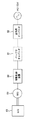
図4は、図1に示す駆動制御装置20を利用した発動発電装置の構成例を示した図である。発動発電装置の構成、動作は基本的に図3に示す車両用発電装置の構成と同じであるので、説明は省略する。
(Application 3)
FIG. 4 is a diagram illustrating a configuration example of the power generation device using the
3.発電機の駆動制御装置の動作
以下、図1に示す駆動制御装置20を図2に示すような風力発電へ適用した場合を例として、駆動制御装置20の動作について説明する。
3. Operation of the Drive Control Device of the Generator The operation of the
最初に基本的な動作を説明する。発電機10の回転子11の回転軸にはプロペラ61が連結されている。このプロペラが受けた風力により発電機10において交流電圧が生成される。この交流電圧はインバータ21により直流電圧に変換され、平滑コンデンサ46により平滑され、バッテリ30に充電される。バッテリ30に充電された電圧は、電源として負荷50に供給される。
First, the basic operation will be described. A
駆動制御装置20は、発電機10を発電機として動作させる場合のモード(発電モード)と、発電機10をモータとして動作(力行動作)させる場合のモード(モータモード)とを有する。発電モードには、出力電圧、出力電力等を制御するための種々の動作モードがある。発電モードは発電制御部27により制御される。また、モータモードは、始動時の起動アシストや、余剰電力を放電させる際に利用される。モータモードはモータ制御部25により制御される。これらの動作モードの詳細は後述する。
The
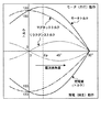
本実施形態の発電システムにおいて、発電機10は、固定子に永久磁石が埋込まれた永久磁石埋込型モータ(IPM)を用いている。IPMは一般的に図5に示すような、電流進角(位相)の絶対値に対するトルク特性を示す。同図において、実線はモータトルク、破線はリラクタンストルク、一点鎖線はマグネットトルクをそれぞれ示す。モータ動作の場合には正の電流進角を示し、発電動作の場合には負の電流進角を示す。同図に示すように、モータ動作時において発生するモータトルクと、発電動作時において発生する発電量は、電流進角の変化に伴い変化する。例えば、発電動作において、電流進角量を0°から増加させていくと、実線で示すモータトルク(すなわち発電量)は増加していき、電流進角βpにおいてピークとなり、その後、減少していく。このように、IPMでは電流進角量を制御することにより発電量を制御することができる。なお、以下の説明では、電流進角量をβpに制御し、最大の発電量が得られるときの状態を「最大発電」といい、電流進角量を90°に制御し、発電量が最小となるときの状態を「最小発電」という。
In the power generation system of the present embodiment, the
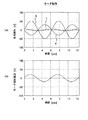
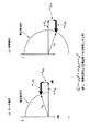
図6(a)は、電流進角量を約90°に制御してIPMをモータ動作(力行動作)させたときの、モータ誘起電圧(E)、モータ電流(I)、d軸電流によるモータ内部の電圧降下(V)の関係を示した図である。同図において、モータ電流(I)は誘起電圧に対し約90°位相が進んでいる。図6(b)は、電流進角量を約90°に制御した場合のモータへの印加電圧を示す。図6に示すようにモータ動作時、電流進角量を正(+)方向に制御した場合、電圧ベクトル図は図8(a)のようになる。巻線抵抗による電圧降下を無視した場合、同図において、ωφaは誘起電圧であり、ωLd・Idはd軸電流による内部電圧降下であり、ωLq・Iqはq軸方向の内部電圧降下であり、Vaはモータ印加電圧であり、Ld、Lqは、固定子巻線のインダクタンスのd軸、q軸方向の成分である。同図に示すように、d軸電流を適宜制御することにより、内部電圧降下分(ωLd・Id)が寄与し、誘起電圧ωφaより小さいモータ印加電圧Vaでの駆動を可能としている。 FIG. 6A shows a motor with motor induced voltage (E), motor current (I), and d-axis current when the IPM is operated to a motor (powering operation) by controlling the current advance amount to about 90 °. It is the figure which showed the relationship of the internal voltage drop (V). In the figure, the motor current (I) is advanced by about 90 ° in phase with respect to the induced voltage. FIG. 6B shows the voltage applied to the motor when the current advance amount is controlled to about 90 °. As shown in FIG. 6, when the current advance amount is controlled in the positive (+) direction during motor operation, the voltage vector diagram is as shown in FIG. If the voltage drop due to the winding resistance is ignored, ωφa is the induced voltage, ωLd · Id is the internal voltage drop due to the d-axis current, and ωLq · Iq is the internal voltage drop in the q-axis direction, Va is a motor applied voltage, and Ld and Lq are d-axis and q-axis components of the inductance of the stator winding. As shown in the figure, by appropriately controlling the d-axis current, the internal voltage drop (ωLd · Id) contributes to enable driving with a motor applied voltage Va smaller than the induced voltage ωφa.
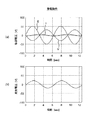
図7(a)は、電流進角量を約−90°に制御してIPMを発電機として動作させたときの、モータ誘起電圧(E)、モータ電流(I)、d軸電流によるモータ内部の電圧降下(V)の関係を示した図である。同図において、モータ電流(I)は誘起電圧に対し約90°位相が遅れている。図7(b)は、電流進角量を約−90°に制御した場合の発電電圧を示す。図7に示すように発電動作時、電流進角量を負(−)方向に制御した場合、電圧ベクトル図は図8(b)のようになる。巻線抵抗による電圧降下を無視した場合、同図において、Vaは発電電圧である。同図に示すように、d軸電流を適宜制御して内部電圧降下成分(ωLd・Id)が寄与し、発電電圧Vaの大きさを一定値に制限することを可能としている。本実施形態では、このようなIPMの弱め界磁制御を利用し、以下に説明する種々の制御を行う。 FIG. 7A shows the interior of the motor by the motor induced voltage (E), the motor current (I), and the d-axis current when the current advance amount is controlled to about −90 ° and the IPM is operated as a generator. It is the figure which showed the relationship of voltage drop (V). In the figure, the motor current (I) is delayed by about 90 ° from the induced voltage. FIG. 7B shows the generated voltage when the current advance amount is controlled to about −90 °. As shown in FIG. 7, when the current advance amount is controlled in the negative (−) direction during the power generation operation, the voltage vector diagram is as shown in FIG. When the voltage drop due to the winding resistance is ignored, Va is the generated voltage in the figure. As shown in the figure, the d-axis current is appropriately controlled and the internal voltage drop component (ωLd · Id) contributes, and the magnitude of the generated voltage Va can be limited to a constant value. In the present embodiment, various types of control described below are performed using such field weakening control of the IPM.
以下に、発電動作時における種々の動作モードについて詳細に説明する。 Hereinafter, various operation modes during the power generation operation will be described in detail.
(出力電圧制御モード)
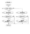
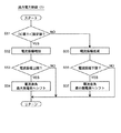
図9のフローチャートを用いて、駆動制御装置20による、発電時の出力電圧を略一定に制御する出力電圧制御を説明する。
(Output voltage control mode)
The output voltage control for controlling the output voltage during power generation to be substantially constant by the
電圧検出部33により検出したインバータ直流出力電圧(以下「DC電圧」という。)Vdcを、その設定値と比較する(S11)。DC電圧Vdcが設定値より小さい場合、インバータ出力電圧が所望値より低いと判断され、電流振幅を所定値だけ増加させる(S12)。このとき、増加させた電流振幅がその上限を超えているか否かを判断する(S13)。増加させた電流振幅が上限を超えていれば、電流振幅を変化させることによる出力電圧の増加は期待できないので、電流進角による出力電圧の上昇を試みる。このため、電流進角を最大発電側へシフトする(S14)。つまり、電流進角を図5におけるβpに近づけるようにシフトする。
The inverter DC output voltage (hereinafter referred to as “DC voltage”) Vdc detected by the
一方、DC電圧Vdcが設定値以上の場合、インバータ出力電圧が所望値より高いと判断され、電流振幅を所定値分低減する(S15)。このとき、低減した電流振幅が電流振幅の下限を下回るか否かを判断する(S16)。低減した電流振幅が下限を下回ったときは、電流振幅を変化させることによる出力電圧の低下は期待できないため、電流進角による出力電圧の低減を試みる。このため、電流進角を最小発電側へシフトする(S17)。つまり、電流進角を図5における90°に近づけるようにシフトする。 On the other hand, if the DC voltage Vdc is equal to or higher than the set value, it is determined that the inverter output voltage is higher than the desired value, and the current amplitude is reduced by a predetermined value (S15). At this time, it is determined whether or not the reduced current amplitude is below the lower limit of the current amplitude (S16). When the reduced current amplitude falls below the lower limit, it is not possible to expect a decrease in the output voltage by changing the current amplitude, so an attempt is made to reduce the output voltage by the current advance angle. Therefore, the current advance angle is shifted to the minimum power generation side (S17). That is, the current advance angle is shifted so as to approach 90 ° in FIG.
なお、ステップS12、S13、S15、S16においては、電流振幅を変化させるかわりにPWM変調率(デューティ)を変化させてもよい。 In steps S12, S13, S15, and S16, the PWM modulation rate (duty) may be changed instead of changing the current amplitude.
出力電圧制御の別の例を図10のフローチャートを用いて説明する。 Another example of output voltage control will be described with reference to the flowchart of FIG.
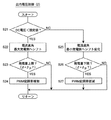
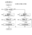
電圧検出部33により検出したインバータの直流出力電圧(DC電圧)Vdcを、その設定値と比較する(S21)。DC電圧Vdcが設定値より小さい場合、インバータ21の出力電圧が所望値より低いと判断され、最大発電側へ電流進角をシフトする(S22)。このとき、発電量(トルク)がその上限を超えているか否かを判断し(S23)、超えていれば、PWM変調率を増加させる(S24)。ここで、発電量(トルク)の上限とは、図5において電流進角量がβpのときの発電量である。
The inverter DC output voltage (DC voltage) Vdc detected by the
一方、DC電圧Vdcが設定値以上の場合、インバータ21の出力電圧が所望値より高いと判断され、最小発電側へ電流進角をシフトする(S25)。このとき、発電量(トルク)がその下限を下回るか否かを判断し(S26)、下回れば、PWM変調率を低減する(S27)。ここで、発電量(トルク)の下限とは、図5において電流進角量が90°のときの発電量である。
On the other hand, when the DC voltage Vdc is equal to or higher than the set value, it is determined that the output voltage of the
なお、ステップS24、S27においては、PWM変調率を変化させるかわりに電流振幅を変化させてもよい。 In steps S24 and S27, the current amplitude may be changed instead of changing the PWM modulation rate.
図9に示す出力電圧制御は電流振幅を優先して制御しているので、負荷の電流変動による比較的小さな電圧変化時に有効である。これに対し、図10に示す出力電圧制御は、電流進角(位相)を優先して制御しているので、回転数変化による比較的大きな電圧変化時に有効である。 Since the output voltage control shown in FIG. 9 is controlled with priority on the current amplitude, it is effective when the voltage change is relatively small due to the load current fluctuation. On the other hand, the output voltage control shown in FIG. 10 is effective when the current advance angle (phase) is prioritized and is controlled at a relatively large voltage change due to a change in the rotational speed.
以上のように、2つの制御の使い分けとしては、負荷や回転数によって使い分けたり、それらの変動を検出して使い分けるのが望ましい。駆動制御装置20によって電流振幅(負荷)及び電流進角を調整することにより発電システムの出力電圧を一定値に制御することができる。なお、電流振幅と電流進角の双方を調整する代わりに、いずれか一方のみを調整するようにしてもよい(以下の制御において同じ)。
As described above, it is desirable to properly use the two controls depending on the load and the number of rotations or to detect and use the fluctuations. By adjusting the current amplitude (load) and the current advance angle by the
(出力電流制御モード)
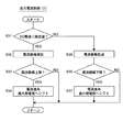
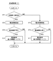
図11のフローチャートを用いて、駆動制御装置20による、発電時の出力電流を略一定に制御する出力電流制御を説明する。
(Output current control mode)
The output current control for controlling the output current during power generation to be substantially constant by the
電流センサ45により検出したインバータ電流(以下「DC電流」という。)Idcを、その設定値と比較する(S31)。DC電流Idcが設定値より小さい場合、インバータ出力電流が所望値より小さいと判断され、電流振幅を所定値分増加させる(S32)。このとき、増加させた電流振幅がその上限を超えているか否かを判断する(S33)。増加させた電流振幅がその上限を超えていれば、電流振幅による出力電流の増加は期待できないため、電流進角による制御を行う。このため、電流進角を最大発電側へシフトする(S34)。
The inverter current (hereinafter referred to as “DC current”) Idc detected by the
一方、DC電流Idcが設定値以上の場合、インバータ出力電流が所望値より大きいと判断され、電流振幅を所定値分低減する(S35)。このとき、低減した電流振幅がその下限を下回るか否かを判断する(S36)。低減した電流振幅がその下限を下回れば、電流振幅による出力電流の増加は期待できないため、電流進角による制御を行う。このため、電流進角を最小発電側へシフトする(S37)。 On the other hand, if the DC current Idc is greater than or equal to the set value, it is determined that the inverter output current is greater than the desired value, and the current amplitude is reduced by a predetermined value (S35). At this time, it is determined whether or not the reduced current amplitude is below the lower limit (S36). If the reduced current amplitude falls below the lower limit, an increase in the output current due to the current amplitude cannot be expected, so control is performed using the current advance angle. Therefore, the current advance angle is shifted to the minimum power generation side (S37).
なお、ステップS32、S33、S35、S36においては、電流振幅を変化させるかわりにPWM変調率(デューティ)を変化させてもよい。 In steps S32, S33, S35, and S36, the PWM modulation rate (duty) may be changed instead of changing the current amplitude.
出力電流制御の別の例を図12のフローチャートを用いて説明する。 Another example of output current control will be described with reference to the flowchart of FIG.
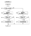
電流センサ45により検出したインバータの直流出力電流(DC電流)Idcを、その設定値と比較する(S41)。DC電流Idcが設定値より小さい場合、インバータ21の出力電圧が所望値より小さいと判断され、電流進角を最大発電側へシフトする(S42)。このとき、発電量がその上限を超えているか否かを判断し(S43)、超えていれば、PWM変調率を増加させる(S44)。
The DC output current (DC current) Idc of the inverter detected by the
一方、DC電流Idcが設定値以上の場合、インバータ21の出力電流が大きいと判断され、電流進角を最小発電側へシフトする(S45)。このとき、発電量がその下限を下回るか否かを判断し(S46)、下回れば、PWM変調率を低減する(S47)。
On the other hand, if the DC current Idc is greater than or equal to the set value, it is determined that the output current of the
なお、ステップS44、S47においては、PWM変調率を変化させるかわりに電流振幅を変化させてもよい。 In steps S44 and S47, the current amplitude may be changed instead of changing the PWM modulation rate.
図11に示す出力電流制御は電流振幅を優先して制御しているので、負荷の電流変動による比較的小さな電流変化時に有効である。これに対し、図12に示す出力電流制御では、電流進角(位相)を優先して制御しているので、回転数変化による比較的大きな電流変化時に有効である。 Since the output current control shown in FIG. 11 is controlled with priority given to the current amplitude, it is effective when a relatively small current change occurs due to a load current fluctuation. On the other hand, in the output current control shown in FIG. 12, the current advance angle (phase) is preferentially controlled, so that it is effective when a relatively large current change occurs due to a change in the rotational speed.
以上のように、駆動制御装置20によって電流振幅(負荷)及び電流進角を調整することにより発電システムの出力電流を一定値に制御することができる。
As described above, the output current of the power generation system can be controlled to a constant value by adjusting the current amplitude (load) and the current advance angle by the
(出力電力制御モード)
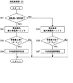
図13のフローチャートを用いて、駆動制御装置20による、発電時の出力電力を略一定に制御する出力電力制御を説明する。
(Output power control mode)
The output power control for controlling the output power during power generation by the
電力検出部35により検出したインバータ21の出力電力(以下「DC電力」という。)Wdcを、その設定値と比較する(S51)。DC電力Wdcが設定値より小さい場合、インバータ21の出力電力が所望値より小さいと判断され、電流振幅を増加させる(S52)。このとき、増加させた電流振幅がその上限を超えているか否かを判断し(S53)、超えていれば、最大発電側へ電流進角をシフトする(S54)。
The output power (hereinafter referred to as “DC power”) Wdc of the
一方、DC電力Wdcが設定値以上の場合、インバータ出力電力が所望値より大きいと判断され、電流振幅を低減する(S55)。このとき、低減した電流振幅がその下限を下回るか否かを判断し(S56)、下回れば、最小発電側へ電流進角(位相)をシフトする(S57)。 On the other hand, if the DC power Wdc is greater than or equal to the set value, it is determined that the inverter output power is greater than the desired value, and the current amplitude is reduced (S55). At this time, it is determined whether or not the reduced current amplitude is below the lower limit (S56). If the current amplitude is lower, the current advance angle (phase) is shifted to the minimum power generation side (S57).
なお、ステップS52、S53、S55、S56においては、電流振幅を変化させるかわりにPWM変調率を変化させてもよい。 In steps S52, S53, S55, and S56, the PWM modulation rate may be changed instead of changing the current amplitude.
出力電力制御の別の例を図14のフローチャートを用いて説明する。 Another example of output power control will be described with reference to the flowchart of FIG.
電力検出部35により検出したインバータの直流出力電力(DC電力)Wdcを、その設定値と比較する(S61)。DC電力Wdcが設定値より小さい場合、インバータ21の出力電力が所望値より小さいと判断され、最大発電側へ電流進角をシフトする(S62)。このとき、発電量がその上限を超えているか否かを判断し(S63)、超えていれば、PWM変調率を増加させる(S64)。
The DC output power (DC power) Wdc of the inverter detected by the
一方、DC電力Wdcが設定値以上の場合、インバータ21の出力電力が所望値より大きいと判断され、最小発電側へ電流進角をシフトする(S65)。このとき、発電量がその下限を下回るか否かを判断し(S66)、下回れば、PWM変調率を低減する(S67)。
On the other hand, if the DC power Wdc is greater than or equal to the set value, it is determined that the output power of the
なお、ステップS64、S67においては、PWM変調率を変化させるかわりに電流振幅を変化させてもよい。 In steps S64 and S67, the current amplitude may be changed instead of changing the PWM modulation rate.
図13に示す出力電力制御は電流振幅を優先して制御しており、負荷変動による小さな電力変化時に有効である。これに対し、図14に示す出力電力制御では、電流進角(位相)を優先して制御しており、回転数変化による大きな電力変化時に有効である。 The output power control shown in FIG. 13 is controlled with priority given to the current amplitude, and is effective when there is a small power change due to load fluctuations. On the other hand, in the output power control shown in FIG. 14, the current advance angle (phase) is preferentially controlled, and is effective at the time of a large power change due to the rotational speed change.
以上のように、2つの制御の使い分けとしては、負荷や回転数によって使い分けたり、それらの変動を検出して使い分けるのが望ましい。駆動制御装置20によって電流振幅(負荷)及び電流進角を調整することにより発電システムの出力電力を一定値に制御することができる。
As described above, it is desirable to properly use the two controls depending on the load and the number of rotations or to detect and use the fluctuations. The output power of the power generation system can be controlled to a constant value by adjusting the current amplitude (load) and the current advance angle by the
(回転数制御モード)
図15のフローチャートを用いて駆動制御装置20による発電時の回転数制御を説明する。
(Rotation speed control mode)
The rotational speed control during power generation by the
回転数検出部31により検出した発電機10の回転数nを、その設定値と比較する(S71)。回転数nが設定値より小さい場合、回転数が所望値より小さいと判断され、電流振幅を低減する(S72)。このとき、低減した電流振幅がその下限を下回るか否かを判断し(S73)、下回れば、最小発電側へ電流進角をシフトする(S74)。
The rotation speed n of the
一方、回転数が設定値以上の場合、回転数が所望値より大きいと判断され、電流振幅を増加する(S75)。このとき、増加した電流振幅がその上限を超えるか否かを判断し(S76)、超えれば、最大発電側へ電流進角をシフトする(S77)。 On the other hand, if the rotational speed is equal to or greater than the set value, it is determined that the rotational speed is greater than the desired value, and the current amplitude is increased (S75). At this time, it is determined whether or not the increased current amplitude exceeds the upper limit (S76), and if it exceeds, the current advance angle is shifted to the maximum power generation side (S77).
なお、ステップS72、S73、S75、S76においては、電流振幅を変化させるかわりにPWM変調率を変化させてもよい。 In steps S72, S73, S75, and S76, the PWM modulation rate may be changed instead of changing the current amplitude.
回転数制御の別の例を図16のフローチャートを用いて説明する。
回転数検出部31により検出した発電機10の回転数nを、その設定値と比較する(S81)。回転数nが設定値より小さい場合、回転数が所望値より小さいと判断され、最小発電側へ電流進角をシフトする(S82)。このとき、発電量がその上限を超えているか否かを判断し(S83)、超えていれば、PWM変調率を低減する(S84)。
Another example of the rotation speed control will be described with reference to the flowchart of FIG.
The rotation speed n of the
一方、回転数nが設定値以上の場合、回転数が所望値より大きいと判断され、最大発電側へ電流進角をシフトする(S85)。このとき、発電量がその下限を下回るか否かを判断し(S86)、下回れば、PWM変調率を増加する(S87)。 On the other hand, if the rotational speed n is equal to or greater than the set value, it is determined that the rotational speed is greater than the desired value, and the current advance angle is shifted to the maximum power generation side (S85). At this time, it is determined whether the power generation amount is below the lower limit (S86), and if it is below, the PWM modulation rate is increased (S87).
なお、ステップS84、S87においては、PWM変調率を変化させるかわりに電流進角を変化させてもよい。 In steps S84 and S87, the current advance angle may be changed instead of changing the PWM modulation rate.
図15に示す回転数制御は電流振幅を優先して制御しており、負荷の電流変動による比較的小さな回転数変化時に有効である。これに対し、図16に示す回転数制御では、電流進角(位相)を優先して制御しており、比較的大きな回転数変化時に有効である。 The rotation speed control shown in FIG. 15 is controlled with priority given to the current amplitude, and is effective when the rotation speed changes relatively small due to the load current fluctuation. On the other hand, in the rotational speed control shown in FIG. 16, the current advance angle (phase) is controlled with priority, and is effective when the rotational speed changes relatively large.
以上のように、駆動制御装置20によって電流振幅(負荷)及び電流進角を調整することにより発電機10の回転数を一定値に制御することができる。
As described above, the rotational speed of the
(始動モード)
発電制御部は、発電機10の始動時の動作モードである始動モードと、発電機10の定常運転状態において発電機を運転する通常動作モードとを有する。通常動作モードでは、発電機10の固定子巻線の誘起電圧v及び巻線電流iに基づいて回転子位置θの検出が行われ、インバータ21のスイッチング素子のオン・オフが制御される。
(Start mode)
The power generation control unit has a start mode that is an operation mode when the
始動モード時の動作について説明する。
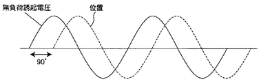
一般に、無負荷誘起電圧と発電機10の回転子位置とは位相が所定値だけずれている(図17参照)。よって、無負荷誘起電圧をモニタすることにより回転子位置を検出することができる。そこで、本実施形態の駆動制御装置20は、発電機10の始動時において、無負荷時の誘起電圧又は無負荷とみなされる程小さい軽負荷時の誘起電圧を検出し、回転子の初期位置を特定する。回転子の初期位置が検出された後、通常動作モードに移行する。なお、この場合、初期位置の代わりに回転数を検出してもよい。また、無負荷とみなされる程小さい軽負荷は、所定の値を基準として判断してもよいし、遮断機41、42をオフにすることで、無負荷と判断してもよい。
The operation in the start mode will be described.
Generally, the no-load induced voltage and the rotor position of the
また、始動時において、発電機10の固定子13を回動しないように固定した状態で固定子13の所定相に通電して位置決めし、その後に、固定を解除し、回転を始動させるようにしてもよい。このようにしても回転子の初期位置を認識できる。
Further, at the time of starting, in a state where the
そして、前記の始動時と、始動モードから通常動作モード移行後、しばらくの間において、発電制御部27は、電流振幅をゼロまたは実質的にゼロに等しい値になるようインバータ21のスイッチング素子のオン・オフを制御する。これにより、始動後、位置検出が安定するまでの間、発電を抑制する。発電を抑制した運転中において、回転子の位置検出が安定した時点で、通常の発電制御を行う。また、始動モード時と、通常運転モードへの移行後しばらくの間において、電流進角を大きくし、発行効率を低下させ、発電を抑制した状態にしてもよい。これは始動モード時では、位置検出が正確に行われないことから、発電機として十分に機能させることができなかったり、位置のアンマッチングにより、発電機に過電流が流れるのを防止するためである。
The power
また、駆動制御装置20は始動時において風力が小さく、風力のみでは、発電機10の回転子が回転しないときは、発電機10をモータとして動作させて発電機10の回転動作を補助するようにしてもよい。
Further, the
(保護機能動作)
駆動制御装置20は保護機能を有している。すなわち、発電制御部27は、電圧検出部33や発電機電圧vに基づき、風速が大きく過電圧が発生していると判断したときは、遮断機41、42を作動させ、一時的に発電機10からの電力供給を遮断する。これにより、発電システムを過電圧による破壊から保護する。
(Protection function operation)
The
また、駆動制御装置20は、電圧検出部33や電流センサ45からの検出値Vdc、Idcにより、負荷からの回生や負荷の増大によって、過電圧、過電流が発生していると判断したときは、遮断機42を作動させる。これにより、過電圧、過電流からインバータ21の破壊を防止する。
Further, when the
また、発電制御部27は、発電機10の故障を検出し、故障が検出されたときに、インバータ21の各スイッチング素子や、短絡用のスイッチを用いて発電機の出力を短絡することで発電機10に制動をかけ、強制的に発電機10の回転を停止させるようにしてもよい。故障については、回転速度ムラが検出されたときや、想定した電圧が得られないとき等に検出できる。なお、回転速度ムラは、発電される電圧や、電流センサ43、44により検出された電流の周波数、波形、リップルを検出することにより判断できる。故障検出時に発電機10を停止させることで、さらなる故障の発生を防止できる。
Further, the power
(その他の制御)
駆動制御装置20は、発電機10の回転数を監視し、回転数が所定値を超えたことが検出された場合(すなわち過剰に発電してしまう場合)は、回転数を抑制するよう制御する。この場合、インバータ21の各スイッチング素子や、短絡用のスイッチを用いて発電機の出力を短絡することでも、モータ回転数を低減することは可能である。このような制御により、風力が非常に強い場合でも、回転数を抑制できる。
(Other control)
The
また、逆に、発電機10の駆動中に風力が弱まり、停止のおそれが生じたときは、バッテリ30から電力を供給して発電機10を力行動作させ、一定の回転数を維持するよう、回転動作を補助するようにするのが好ましい。これは、風力発電システムにおいて一旦回転を停止させると、再度起動する際には多大な負荷がかかるため、回転を維持させることが重要であるからである。
On the other hand, when the wind power is weakened during driving of the
以上のように、本実施形態の発電システムはインバータ21を備え、これを用いて負荷量(モータ電流振幅)及び電流進角量を調整する。これにより、きめ細やかな出力電圧、出力電流、出力電力等の制御が可能となる。
As described above, the power generation system of the present embodiment includes the
(バッテリ充電)
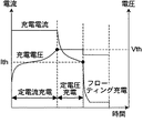
図18はバッテリ30の充電方法を説明した図である。図18に示すような充電方法で充電するため、駆動制御装置20は次のような制御を行う。
(Battery charging)
FIG. 18 is a diagram illustrating a method for charging the
駆動制御装置20は、充電開始後しばらくは、図11、12のフローチャートで示した出力電流制御を行って、バッテリ30に対して一定電流での充電を行う。そして、バッテリ30の電圧が所定値Vthに達すると、図9、10のフローチャートで示した出力電圧制御に切替え、バッテリ30に対して一定電圧での充電を行う。これによりバッテリの充電電流は低下していき、やがて、バッテリの充電電流が所定値Ithに達すると、駆動制御装置20は、出力電圧の設定値をより低い値に変更して出力電圧制御を継続する。その後、充電電流が定常状態になった時点で充電を終了する。
For a while after the start of charging, the
(キャパシタ充電)
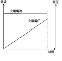
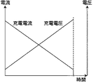
図1においてバッテリ30の代わりにキャパシタを使用することもできる。キャパシタの充電方法は図19または図20に示す方法がある。
(Capacitor charging)
In FIG. 1, a capacitor can be used instead of the
図19に示す方法により充電する場合、駆動制御装置20は、図11、12のフローチャートで示した出力電流制御を行うことにより、終始、出力電流を一定に保持しながらキャパシタを充電する。また、図20に示す方法により充電する場合、駆動制御装置20は、図13、14のフローチャートで示した出力電力制御を行うことにより、出力電力を一定に保持しながらキャパシタを充電する。
In the case of charging by the method shown in FIG. 19, the
なお、上記の動作説明では、風力を動力源として発電システムについて説明したが、動力源は風力に限らず、他の動力源であっても本発明の技術思想は同様に適用できることは言うまでもない。 In the above description of the operation, the power generation system has been described using wind power as a power source. However, it goes without saying that the technical idea of the present invention can be similarly applied to other power sources as well as the power source.
本発明は、発電機の位置センサレス駆動を行う駆動制御装置に適用であって、小型化、高い信頼性が要求される駆動制御装置に有用である。例えば、風力を動力源とした風力発電システムに好適である。 The present invention is applicable to a drive control apparatus that performs position sensorless drive of a generator, and is useful for a drive control apparatus that requires downsizing and high reliability. For example, it is suitable for a wind power generation system using wind power as a power source.
10 発電機
11 発電機の回転子
13 発電機の固定子
20 発電機の駆動制御装置
23 PWM電圧制御部
25 モータ制御部
27 発電制御部
29 回転子位置検出部
30 バッテリ(キャパシタ)
31 回転数検出部
33 電圧検出部
35 電力検出部
43、44 電流センサ
41、42 遮断機
46 平滑コンデンサ
50 負荷
β 電流進角量
ω 発電機回転角速度(電気角)
iq q軸電流成分
id d軸電流成分
φa 磁束
DESCRIPTION OF
31 Rotational
iq q-axis current component id d-axis current component φa magnetic flux
Claims (18)
複数の整流ダイオードと複数のスイッチング素子を含み、前記発電機で発電された交流電力を直流電力に変換する発電用インバータと、
前記インバータのスイッチング素子のオン・オフを制御して発電出力を制御する制御手段とを備え、
前記制御手段は前記固定子巻線の誘起電圧に基づいて前記回転子位置を検出し、該検出した回転子位置に応じて固定子巻線電流の電流進角及び電流振幅の少なくともいずれかを制御することにより、出力電圧及び出力電流の少なくともいずれかを制御することを特徴とする発電機の駆動制御装置。 A device for driving a generator including a rotor and a stator embedded with permanent magnets in a position sensorless manner,
A generator inverter that includes a plurality of rectifier diodes and a plurality of switching elements, and converts AC power generated by the generator into DC power;
Control means for controlling the on / off of the switching element of the inverter to control the power generation output,
The control means detects the rotor position based on the induced voltage of the stator winding, and controls at least one of the current advance angle and current amplitude of the stator winding current according to the detected rotor position. By doing so, at least one of the output voltage and the output current is controlled.
固定子巻線電流の電流進角及び電流振幅を制御し、出力電圧を略一定に制御する定電圧制御モード、
固定子巻線電流の電流進角及び電流振幅を制御し、出力電流を略一定に制御する定電流制御モード、
固定子巻線電流の電流進角及び電流振幅を制御し、出力電力を略一定に制御する定電力制御モード、及び
固定子巻線電流の電流進角及び電流振幅を制御し、前記発電機の回転数を略一定に制御する回転数制御モード
のうちの少なくとも1つの動作モードを有することを特徴とする請求項1記載の発電機の駆動制御装置。 The control means includes
Constant voltage control mode for controlling the current advance angle and current amplitude of the stator winding current and controlling the output voltage substantially constant,
Constant current control mode for controlling the current advance angle and current amplitude of the stator winding current and controlling the output current to be substantially constant,
A constant power control mode for controlling the current advance angle and current amplitude of the stator winding current and controlling the output power to be substantially constant; and controlling the current advance angle and current amplitude of the stator winding current; 2. The generator drive control device according to claim 1, further comprising at least one operation mode of a rotation speed control mode for controlling the rotation speed to be substantially constant.
When the electric power converted by the inverter is stored in a capacitor and the electric power is supplied to the load via the capacitor, the control means charges the capacitor while controlling the charging power to be constant in the constant power control mode. The generator drive control device according to claim 13.
Priority Applications (1)
| Application Number | Priority Date | Filing Date | Title |
|---|---|---|---|
| JP2004104161A JP2005295626A (en) | 2004-03-31 | 2004-03-31 | Generator drive control device |
Applications Claiming Priority (1)
| Application Number | Priority Date | Filing Date | Title |
|---|---|---|---|
| JP2004104161A JP2005295626A (en) | 2004-03-31 | 2004-03-31 | Generator drive control device |
Publications (1)
| Publication Number | Publication Date |
|---|---|
| JP2005295626A true JP2005295626A (en) | 2005-10-20 |
Family
ID=35327964
Family Applications (1)
| Application Number | Title | Priority Date | Filing Date |
|---|---|---|---|
| JP2004104161A Pending JP2005295626A (en) | 2004-03-31 | 2004-03-31 | Generator drive control device |
Country Status (1)
| Country | Link |
|---|---|
| JP (1) | JP2005295626A (en) |
Cited By (11)
| Publication number | Priority date | Publication date | Assignee | Title |
|---|---|---|---|---|
| JP2008238856A (en) * | 2007-03-26 | 2008-10-09 | Honda Motor Co Ltd | Control device for motor generator |
| JP2010161889A (en) * | 2009-01-09 | 2010-07-22 | Kochi Univ Of Technology | Power-generating apparatus |
| DE102011087876A1 (en) | 2010-12-07 | 2012-06-14 | Toshiba Kikai K.K. | Inverter generator |
| DE102011087875A1 (en) | 2010-12-07 | 2012-06-14 | Toshiba Kikai K.K. | Inverter generator |
| KR20150013230A (en) * | 2012-05-04 | 2015-02-04 | 지멘스 악티엔게젤샤프트 | Synchronous generator control, generator system and vessel energy system |
| JP2015505235A (en) * | 2011-12-19 | 2015-02-16 | ゼットビービー エナジー コーポレーション | System and method for low speed control of a polyphase alternator |
| JP2015084615A (en) * | 2013-10-25 | 2015-04-30 | 株式会社デンソー | Rotating electric machine for vehicles |
| CN109018378A (en) * | 2018-08-24 | 2018-12-18 | 北京瑞深航空科技有限公司 | Oily electricity mixed power supply system and its power generation control and method, unmanned plane |
| CN112930648A (en) * | 2018-10-16 | 2021-06-08 | 株式会社电装 | Power conversion device |
| WO2022168290A1 (en) * | 2021-02-05 | 2022-08-11 | 本田技研工業株式会社 | Power generator |
| WO2025037451A1 (en) * | 2023-08-14 | 2025-02-20 | 国立研究開発法人宇宙航空研究開発機構 | Protection system and protection device |
-
2004
- 2004-03-31 JP JP2004104161A patent/JP2005295626A/en active Pending
Cited By (17)
| Publication number | Priority date | Publication date | Assignee | Title |
|---|---|---|---|---|
| JP2008238856A (en) * | 2007-03-26 | 2008-10-09 | Honda Motor Co Ltd | Control device for motor generator |
| JP2010161889A (en) * | 2009-01-09 | 2010-07-22 | Kochi Univ Of Technology | Power-generating apparatus |
| DE102011087876A1 (en) | 2010-12-07 | 2012-06-14 | Toshiba Kikai K.K. | Inverter generator |
| DE102011087875A1 (en) | 2010-12-07 | 2012-06-14 | Toshiba Kikai K.K. | Inverter generator |
| US8803345B2 (en) | 2010-12-07 | 2014-08-12 | Toshiba Kikai Kabushiki Kaisha | Inverter generator |
| US8916982B2 (en) | 2010-12-07 | 2014-12-23 | Toshiba Kikai Kabushiki Kaisha | Inverter generator |
| JP2015505235A (en) * | 2011-12-19 | 2015-02-16 | ゼットビービー エナジー コーポレーション | System and method for low speed control of a polyphase alternator |
| US10505479B2 (en) | 2012-05-04 | 2019-12-10 | Siemens Aktiengesellschaft | Synchronous generator control, generator system and vessel energy system |
| KR20150013230A (en) * | 2012-05-04 | 2015-02-04 | 지멘스 악티엔게젤샤프트 | Synchronous generator control, generator system and vessel energy system |
| KR102109310B1 (en) * | 2012-05-04 | 2020-05-29 | 지멘스 악티엔게젤샤프트 | Synchronous generator control, generator system and vessel energy system |
| JP2015084615A (en) * | 2013-10-25 | 2015-04-30 | 株式会社デンソー | Rotating electric machine for vehicles |
| CN109018378A (en) * | 2018-08-24 | 2018-12-18 | 北京瑞深航空科技有限公司 | Oily electricity mixed power supply system and its power generation control and method, unmanned plane |
| CN109018378B (en) * | 2018-08-24 | 2021-01-19 | 北京瑞深航空科技有限公司 | Oil-electricity hybrid power supply system, power generation control device and method thereof, and unmanned aerial vehicle |
| CN112930648A (en) * | 2018-10-16 | 2021-06-08 | 株式会社电装 | Power conversion device |
| CN112930648B (en) * | 2018-10-16 | 2024-03-19 | 株式会社电装 | power conversion device |
| WO2022168290A1 (en) * | 2021-02-05 | 2022-08-11 | 本田技研工業株式会社 | Power generator |
| WO2025037451A1 (en) * | 2023-08-14 | 2025-02-20 | 国立研究開発法人宇宙航空研究開発機構 | Protection system and protection device |
Similar Documents
| Publication | Publication Date | Title |
|---|---|---|
| JP4021431B2 (en) | Converter device, inverter device, and DC link voltage control method | |
| JP3517405B2 (en) | Control device and control method for rotating electric machine for vehicle | |
| EP2345146B1 (en) | Motor driver and method of controlling the same | |
| US6528967B2 (en) | Permanent magnet brushless electric motor system and method of using same | |
| JP4236870B2 (en) | Control device and control method for rotating electrical machine for vehicle | |
| EP2157688A1 (en) | Motor driving device, motor device, and integrated circuit device | |
| JP2010035259A (en) | Inverter generator | |
| US8339074B2 (en) | Power converter control apparatus | |
| EP1236269A1 (en) | Switched reluctance generator and a method of controlling such a generator | |
| US7545122B2 (en) | Control method of generator | |
| JP4082338B2 (en) | Control device and control method for motor-driven 4WD vehicle | |
| JP2005295626A (en) | Generator drive control device | |
| JP2007215277A (en) | Vehicle power generation control device | |
| US8975843B2 (en) | Motor control device | |
| JP4950162B2 (en) | Vehicle power supply | |
| JP4478185B2 (en) | Engine starter for vehicle | |
| JP2014180172A (en) | Dynamoelectric machine for vehicle | |
| JP4756251B2 (en) | Control method of DC brushless motor for electric vehicle | |
| US11491879B2 (en) | Sequential electrical braking with pulsed DC injection rotor lock mechanism | |
| JP6119531B2 (en) | Rotating electric machine for vehicles | |
| JP4560710B2 (en) | Power generation system | |
| JP2007159354A (en) | Control device for rotating electrical machine for vehicle | |
| JP2014087195A (en) | Rotary electric machine for vehicle | |
| JP2013255389A (en) | Electric motor | |
| JP4049698B2 (en) | Motor control device |
Legal Events
| Date | Code | Title | Description |
|---|---|---|---|
| RD03 | Notification of appointment of power of attorney |
Free format text: JAPANESE INTERMEDIATE CODE: A7423 Effective date: 20061206 |