JP2005295618A - Power generation control device for hybrid vehicle - Google Patents
Power generation control device for hybrid vehicle Download PDFInfo
- Publication number
- JP2005295618A JP2005295618A JP2004103630A JP2004103630A JP2005295618A JP 2005295618 A JP2005295618 A JP 2005295618A JP 2004103630 A JP2004103630 A JP 2004103630A JP 2004103630 A JP2004103630 A JP 2004103630A JP 2005295618 A JP2005295618 A JP 2005295618A
- Authority
- JP
- Japan
- Prior art keywords
- power generation
- power
- generation amount
- drive
- generator
- Prior art date
- Legal status (The legal status is an assumption and is not a legal conclusion. Google has not performed a legal analysis and makes no representation as to the accuracy of the status listed.)
- Pending
Links
- 238000010248 power generation Methods 0.000 title claims abstract description 158
- 230000008859 change Effects 0.000 claims abstract description 46
- 230000004043 responsiveness Effects 0.000 abstract description 6
- 238000010586 diagram Methods 0.000 description 14
- 238000000034 method Methods 0.000 description 8
- 230000008878 coupling Effects 0.000 description 7
- 238000010168 coupling process Methods 0.000 description 7
- 238000005859 coupling reaction Methods 0.000 description 7
- 238000004891 communication Methods 0.000 description 5
- 230000007246 mechanism Effects 0.000 description 4
- 230000008569 process Effects 0.000 description 4
- 230000009467 reduction Effects 0.000 description 4
- 238000002360 preparation method Methods 0.000 description 3
- 230000004044 response Effects 0.000 description 3
- 239000007858 starting material Substances 0.000 description 3
- 230000001133 acceleration Effects 0.000 description 2
- 230000005540 biological transmission Effects 0.000 description 2
- 230000007423 decrease Effects 0.000 description 2
- 230000001172 regenerating effect Effects 0.000 description 2
- 230000001360 synchronised effect Effects 0.000 description 2
- 239000003990 capacitor Substances 0.000 description 1
- 230000009194 climbing Effects 0.000 description 1
- 238000002485 combustion reaction Methods 0.000 description 1
- 230000000994 depressogenic effect Effects 0.000 description 1
- 238000001514 detection method Methods 0.000 description 1
- 238000007599 discharging Methods 0.000 description 1
- 230000000694 effects Effects 0.000 description 1
- 239000000446 fuel Substances 0.000 description 1
- 238000012986 modification Methods 0.000 description 1
- 230000004048 modification Effects 0.000 description 1
- 238000004904 shortening Methods 0.000 description 1
Images

Classifications
-
- Y—GENERAL TAGGING OF NEW TECHNOLOGICAL DEVELOPMENTS; GENERAL TAGGING OF CROSS-SECTIONAL TECHNOLOGIES SPANNING OVER SEVERAL SECTIONS OF THE IPC; TECHNICAL SUBJECTS COVERED BY FORMER USPC CROSS-REFERENCE ART COLLECTIONS [XRACs] AND DIGESTS
- Y02—TECHNOLOGIES OR APPLICATIONS FOR MITIGATION OR ADAPTATION AGAINST CLIMATE CHANGE
- Y02T—CLIMATE CHANGE MITIGATION TECHNOLOGIES RELATED TO TRANSPORTATION
- Y02T10/00—Road transport of goods or passengers
- Y02T10/60—Other road transportation technologies with climate change mitigation effect
- Y02T10/7072—Electromobility specific charging systems or methods for batteries, ultracapacitors, supercapacitors or double-layer capacitors
Landscapes
- Hybrid Electric Vehicles (AREA)
- Electric Propulsion And Braking For Vehicles (AREA)
Abstract
【課題】 発電時のエンジン効率を向上させるとともに、応答性を向上させて運転者に良好なフィーリングを与える。
【解決手段】 ハイブリッド車両は、ジェネレータを駆動するエンジンと駆動輪を駆動する駆動モータとを備えており、ジェネレータからの電力を蓄えるとともに、駆動モータに電力を供給する駆動用バッテリを備えている。駆動系制御ユニットは、電流Ibatと電圧Vbatとに基づいて駆動用バッテリの充放電電力Wbatを算出し、この充放電電力Wbatを積算した電力積算値Ebatを算出する。次いで、算出周期Tpre毎に電力積算値Ebatの変化率である積算値変化率DEbatを算出した後に、この積算値変化率DEbatに基づいて目標発電量Wgenを設定する。非発電時には停止時周期Tevが算出周期Tpreとして設定され、発電時には停止時周期Tevより短い発電時周期Tgenが算出周期Tpreとして設定される。
【選択図】 図4
PROBLEM TO BE SOLVED: To improve engine efficiency during power generation and improve responsiveness to give a driver a good feeling.
A hybrid vehicle includes an engine that drives a generator and a drive motor that drives drive wheels, and includes a drive battery that stores power from the generator and supplies power to the drive motor. The drive system control unit calculates the charge / discharge power Wbat of the drive battery based on the current Ibat and the voltage Vbat, and calculates a power integrated value Ebat obtained by integrating the charge / discharge power Wbat. Next, after calculating the integrated value change rate DEbat, which is the change rate of the power integrated value Ebat, every calculation cycle Tpre, the target power generation amount Wgen is set based on the integrated value change rate DEbat. The stop period Tev is set as the calculation period Tpre during non-power generation, and the generation period Tgen shorter than the stop period Tev is set as the calculation period Tpre during power generation.
[Selection] Figure 4
Description
本発明は、発電機を駆動するエンジンと駆動輪を駆動する電動モータとを有するハイブリッド車両の発電制御装置に関する。 The present invention relates to a power generation control device for a hybrid vehicle having an engine for driving a generator and an electric motor for driving driving wheels.
近年、エンジンおよび電動モータを動力源として搭載するようにしたハイブリッド車両が開発されている。このようなハイブリッド車両は、発進時や低速時の動力源として低回転から高トルクを発生する電動モータを用いることにより、エンジンの使用領域を効率の良い領域に絞ることができるため、エンジン効率を向上させて低燃費を達成することができる。 In recent years, hybrid vehicles in which an engine and an electric motor are mounted as power sources have been developed. Such a hybrid vehicle uses an electric motor that generates a high torque from a low rotation as a power source at the time of starting or at a low speed, so that the use area of the engine can be narrowed down to an efficient area. It can improve and achieve low fuel consumption.
このハイブリッド車両の駆動方式としては、電動モータのみを用いて駆動輪を駆動するようにしたシリーズ方式、電動モータとエンジンとを用いて駆動輪を駆動するようにしたパラレル方式、そしてシリーズ方式とパラレル方式とを組み合わせるようにしたシリーズ・パラレル方式が開発されている。 As a drive system of this hybrid vehicle, a series system in which driving wheels are driven using only an electric motor, a parallel system in which driving wheels are driven using an electric motor and an engine, and a series system and parallel A series / parallel system has been developed that combines this with other systems.
シリーズ方式やシリーズ・パラレル方式の車両にあっては、エンジンに駆動される発電機つまりジェネレータが搭載されており、ジェネレータから発電された電力は、駆動輪を駆動するために電動モータに供給されるとともに、発進時や加速時等に備えて蓄電手段であるバッテリに充電される。このジェネレータの目標発電量はバッテリの充電状態に基づいて設定されることが多く、たとえば、バッテリの充放電電流量に基づいて目標発電量を設定するようにした発電制御装置が開発されている(たとえば、特許文献1参照)。
特許文献1に記載の発電制御装置にあっては、固定された算出周期毎に充放電電流量を算出するようになっている。しかしながら、一定の算出周期に従って充放電電流量を算出することは、ジェネレータを駆動するエンジンの効率を低下させたり、アクセル操作量と発電量との相違から運転者に違和感を与えたりする要因となっていた。 In the power generation control device described in Patent Document 1, the charge / discharge current amount is calculated for each fixed calculation cycle. However, calculating the amount of charge / discharge current according to a certain calculation cycle is a factor that decreases the efficiency of the engine that drives the generator and makes the driver feel uncomfortable due to the difference between the accelerator operation amount and the power generation amount. It was.
つまり、算出周期を短く設定した場合には、ジェネレータの発電量が振動的に変更されることから、エンジンの駆動状態を頻繁に変更する必要があり、エンジン効率を低下させることになる。一方、算出周期を長く設定した場合には、発電量を設定する際に生じる応答遅れによって、運転者が要求する駆動力とこれを具現化する発電量との差が広がることになり、運転者に違和感を与えることになる。このように、固定された算出周期に従って発電量を設定した場合には、発電時のエンジン効率を向上させるとともに、応答性を向上させて運転者に良好なフィーリングを与えることが困難であった。 That is, when the calculation cycle is set to be short, the power generation amount of the generator is changed oscillatingly, so it is necessary to frequently change the driving state of the engine, resulting in a reduction in engine efficiency. On the other hand, when the calculation cycle is set to be long, the difference between the driving force required by the driver and the amount of power generation that embodies it increases due to the response delay that occurs when setting the power generation amount. Will give a sense of incongruity. Thus, when the power generation amount is set according to the fixed calculation cycle, it is difficult to improve engine efficiency during power generation and improve responsiveness to give the driver a good feeling. .
本発明の目的は、発電時のエンジン効率を向上させるとともに、応答性を向上させて運転者に良好なフィーリングを与えることにある。 An object of the present invention is to improve engine efficiency during power generation and improve responsiveness to give the driver a good feeling.
本発明のハイブリッド車両の発電制御装置は、発電機を駆動するエンジンと駆動輪を駆動する電動モータとを有するハイブリッド車両の発電制御装置であって、前記発電機からの電力を蓄え、前記電動モータに電力を供給する蓄電手段と、前記蓄電手段の電力量変化率を所定周期毎に算出する変化率算出手段と、前記電力量変化率に基づいて目標発電量を設定する発電量設定手段と、前記目標発電量に基づいて前記発電機を制御する発電制御手段とを有し、前記所定周期を車両状態に基づいて変化させることを特徴とする。 A power generation control device for a hybrid vehicle according to the present invention is a power generation control device for a hybrid vehicle having an engine that drives a generator and an electric motor that drives a drive wheel, and stores electric power from the generator, and the electric motor Power storage means for supplying power to the battery, change rate calculation means for calculating a power amount change rate of the power storage means for each predetermined period, power generation amount setting means for setting a target power generation amount based on the power amount change rate, Power generation control means for controlling the generator based on the target power generation amount, and changing the predetermined cycle based on a vehicle state.
本発明のハイブリッド車両の発電制御装置は、前記発電機が発電状態であるか否かに基づいて前記所定周期を変化させることを特徴とする。 The power generation control device for a hybrid vehicle according to the present invention is characterized in that the predetermined period is changed based on whether or not the power generator is in a power generation state.
本発明のハイブリッド車両の発電制御装置は、前記所定周期を前記電力量変化率に基づいて変化させることを特徴とする。 The power generation control device for a hybrid vehicle according to the present invention is characterized in that the predetermined period is changed based on the power amount change rate.
本発明のハイブリッド車両の発電制御装置は、前記発電量設定手段は、前記電力量変化率に基づいて発電量補正値を設定し、前記発電量補正値を用いて目標発電量を設定することを特徴とする。 In the power generation control device for a hybrid vehicle according to the present invention, the power generation amount setting means sets a power generation amount correction value based on the power amount change rate, and sets a target power generation amount using the power generation amount correction value. Features.
本発明によれば、所定周期を車両状態に基づいて変化させるようにしたので、
目標発電量の変更が必要とされない車両状態にあっては、所定周期を長く設定することによって目標発電量の変動を抑制することができ、発電時のエンジン効率を向上させることができる。一方、目標発電量の変更が必要な車両状態にあっては、所定周期を短く設定することによって応答良く目標発電量を更新することができ、運転者に良好なフィーリングを与えることができる。
According to the present invention, the predetermined period is changed based on the vehicle state.
In a vehicle state where the change of the target power generation amount is not required, the target power generation amount can be prevented from changing by setting the predetermined period longer, and the engine efficiency during power generation can be improved. On the other hand, in a vehicle state where the target power generation amount needs to be changed, the target power generation amount can be updated with good response by setting the predetermined cycle short, and the driver can have a good feeling.
また、発電機が発電状態であるか否かに基づいて所定周期を変化させるようにようにしたので、非発電状態にあっては所定周期を長く設定することにより、発電開始直後に設定される目標発電量を安定させることができる。そして、発電状態にあっては所定周期を短く設定することにより、車両状態に応じた目標発電量を応答良く設定することができる。 In addition, since the predetermined period is changed based on whether or not the generator is in the power generation state, it is set immediately after the start of power generation by setting the predetermined period longer in the non-power generation state. The target power generation amount can be stabilized. In the power generation state, the target power generation amount corresponding to the vehicle state can be set with good response by setting the predetermined cycle short.
さらに、電力量変化率に基づいて所定周期を変化させるようにしたので、車両状態が急激に変動した場合であっても所定周期を短く設定することができ、車両状態の急激な変動に対する目標発電量の応答性を向上させることができる。 In addition, since the predetermined cycle is changed based on the rate of change in the electric energy, the predetermined cycle can be set short even when the vehicle state fluctuates abruptly, and the target power generation for a sudden change in the vehicle state The amount of responsiveness can be improved.
さらに、発電量補正値を用いて目標発電量を設定することにより、目標発電量の急激な変動を抑制することができ、エンジン効率を高めることができるとともに、運転者に良好なフィーリングを与えることができる。 Furthermore, by setting the target power generation amount using the power generation amount correction value, rapid fluctuations in the target power generation amount can be suppressed, the engine efficiency can be increased, and a good feeling can be given to the driver. be able to.
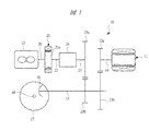
以下、本発明の実施の形態を図面に基づいて詳細に説明する。図1はハイブリッド車両の駆動装置10を示す概略図である。図1に示す駆動装置10は、前輪駆動用のハイブリッド車両に適用される駆動装置10であり、動力源として電動モータである駆動モータ11と内燃機関であるエンジン12とを有している。駆動モータ11はモータ側駆動歯車13aが固定されたモータ出力軸14を有しており、これに平行となる前輪駆動軸15にはモータ側駆動歯車13aに噛み合うモータ側従動歯車13bが固定されている。また、前輪駆動軸15の先端には終減速小歯車16が固定されており、この終減速小歯車16に噛み合う終減速大歯車17には図示しないディファレンシャル機構が組み付けられる。ディファレンシャル機構から車幅方向に伸びる車軸18は、駆動輪としての前輪に連結されており、駆動モータ11から前輪駆動軸15を介して伝達されるモータ動力は、ディファレンシャル機構を介して左右の前輪に伝達されることになる。
Hereinafter, embodiments of the present invention will be described in detail with reference to the drawings. FIG. 1 is a schematic diagram showing a
また、エンジン12のクランク軸20には発電機つまりジェネレータ21が取り付けられており、ジェネレータ21のロータ21aにはロータ出力軸22が固定されている。ロータ出力軸22とこれの同軸上に配置されるエンジン出力軸23との間には、エンジン動力を伝達する締結状態と遮断する解放状態とに作動するカップリング24が設けられている。さらに、エンジン出力軸23にはエンジン側駆動歯車25aが固定され、前輪駆動軸15にはエンジン側駆動歯車25aに噛み合うエンジン側従動歯車25bが固定されており、カップリング24を締結状態に切り換えることによって、エンジン動力が前輪駆動軸15を介して前輪に伝達されるようになっている。エンジン動力を伝達するカップリング24としては、図示しない電磁コイルに対する通電制御によって作動する噛み合い式の2ウェイクラッチが使用されているが、通電制御によって作動する摩擦クラッチを設けるようにしても良い。
A generator or
なお、エンジン12のクランク軸20に連結されるジェネレータ21は、エンジン動力によって発電する機能だけでなく、スタータモータとしての機能を有している。このため、ジェネレータ21をスタータモータとして駆動することにより、エンジン12を始動することができるようになっている。また、駆動モータ11は発電機としての機能を有しており、車両制動時に駆動モータ11を発電機として作動させることで、運動エネルギーを電気エネルギーに変換して回収することができるようになっている。
The
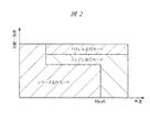
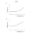
このような駆動モータ11とエンジン12を備えるハイブリッド車両は、モータ動力のみを駆動輪に伝達するシリーズ走行モード、エンジン動力のみを駆動輪に伝達するエンジン走行モード、モータ動力とエンジン動力との双方を駆動輪に伝達するパラレル走行モードを備えており、これらの走行モードは走行状況に応じて切り換えられる。ここで、図2は走行モード切換特性の一例を示す特性線図である。図2に示すように、車速、勾配、負荷などに応じて走行モードが設定されるようになっており、大きな駆動トルクが要求される低中速時にはシリーズ走行モードが設定され、エンジン12を高回転域で効率良く駆動することができる高速時(たとえば、80Km/h以上)にはエンジン走行モードが設定され、加速時や登坂時などの高負荷時にはパラレル走行モードが設定されるようになっている。
Such a hybrid vehicle including the
これら走行モードの切り換えは、エンジン12と前輪駆動軸15との間に設けられるカップリング24を切換制御することによって実行される。つまり、エンジン走行モードやパラレル走行モードを実行する際には、エンジン動力を前輪駆動軸15に伝達するため、カップリング24が締結状態に切り換えられる一方、前輪駆動軸15に対してエンジン動力を遮断するシリーズ走行モードにあっては、カップリング24は解放状態に切り換えられ、前輪駆動軸15に対してエンジン12が切り離された状態となる。そして、シリーズ走行モードにおいて、ジェネレータ21による発電が必要な走行状況になると、ジェネレータ21を用いてエンジン12が始動された後に、エンジン12が効率の良い回転数領域でジェネレータ21を駆動することになる。なお、エンジン走行モードやパラレル走行モードであっても、エンジン12にかかる負荷が少ない場合には、車両状態に応じて余剰動力を用いた発電制御が実行されることになる。
Switching between these travel modes is performed by switching control of a
図3はハイブリッド車両の電気系および制御系を示すブロック図である。図3に示すように、ハイブリッド車両は各種制御ユニット30〜32を備えており、これらの制御ユニット30〜32によって、各駆動部の駆動状態が検出されるとともに各駆動部に制御信号が出力されている。これらの制御ユニット30〜32は通信ケーブルを介して相互に接続されており、ハイブリッド車両には制御ユニット間で検出信号や制御信号を相互に通信するための通信ネットワーク33が構築されている。なお、各制御ユニット30〜32には、制御信号を演算するCPUが設けられるとともに、制御プログラム、演算式およびマップデータ等を格納するROMや、一時的にデータを格納するRAMが設けられている。
FIG. 3 is a block diagram showing an electric system and a control system of the hybrid vehicle. As shown in FIG. 3, the hybrid vehicle includes
図3に示すように、ハイブリッド車両には、ジェネレータ21によって発電された電力を蓄えるとともに、駆動モータ11に電力を供給する蓄電手段としての駆動用バッテリ34が搭載されている。この駆動用バッテリ34にはバッテリ制御ユニット30が設けられており、バッテリ制御ユニット30によって、駆動用バッテリ34の電圧Vbat、電流Ibat、セル温度等が検出される。そして、電圧Vbat、電流Ibat、セル温度に基づいて、バッテリ制御ユニット30は駆動用バッテリ34の充電状態SOC(state of charge)を算出するようになっている。なお、蓄電手段として駆動用バッテリ34が搭載されているが、これに代えてキャパシタを搭載するようにしても良い。
As shown in FIG. 3, the hybrid vehicle is equipped with a driving
また、駆動用バッテリ34とジェネレータ21との間には、ジェネレータ用のインバータ35が設けられており、交流同期型モータのジェネレータ21によって発電された交流電流は、インバータ35を介して直流電流に変換された後に、駆動用バッテリ34に充電されるようになっている。そして、ジェネレータ21をスタータモータとして駆動する際には、駆動用バッテリ34からの直流電流が、インバータ35を介して交流電流に変換された後に、ジェネレータ21に供給されることになる。
A
同様に、駆動用バッテリ34と駆動モータ11との間には、駆動モータ用のインバータ36が設けられており、駆動用バッテリ34からの直流電流が、インバータ36を介して交流電流に変換された後に、交流同期型モータの駆動モータ11に供給されるようになっている。そして、回生ブレーキによって発電された交流電流、つまり車両の制動時に駆動モータ11によって発電された交流電流は、インバータ36を介して直流電流に変換された後に、駆動用バッテリ34に充電されることになる。
Similarly, a
また、ハイブリッド車両にはエンジン12を駆動制御するエンジン制御ユニット31が設けられており、エンジン制御ユニット31には各種センサからエンジン12の駆動状態が入力されている。さらに、エンジン制御ユニット31には、アクセル開度、車速、シフトレンジ等の信号が、後述する駆動系制御ユニット32から通信ネットワーク33を介して入力されている。これらの各種信号に基づいて、エンジン制御ユニット31は、スロットルバルブ、インジェクタ、イグナイタ等に対して制御信号を出力することにより、エンジン12の駆動状態を制御するようになっている。
Further, the hybrid vehicle is provided with an
さらに、ハイブリッド車両には駆動装置10を駆動制御する駆動系制御ユニット32が設けられている。この駆動系制御ユニット32には、アクセル開度を検出するアクセルペダルセンサ37や、シフトレンジを検出するシフトポジションセンサ38が接続されるとともに、ロータ出力軸22、エンジン出力軸23、前輪駆動軸15等の回転数を検出する図示しない回転数センサが接続されている。さらには、通信ネットワーク33を介して、エンジン12、駆動モータ11およびジェネレータ21の各駆動状態や、駆動用バッテリ34の充電状態SOC、電流Ibat、および電圧Vbat等が入力されている。そして、駆動系制御ユニット32は、アクセルペダルセンサ37から入力されるアクセル開度と前輪駆動軸15の回転数から演算される車速とに基づいて走行モードを設定するとともに、入力された各種信号に基づいて、カップリング24、エンジン制御ユニット31、インバータ35,36に対して制御信号を出力するようになっている。
Further, the hybrid vehicle is provided with a drive
このような各制御ユニット30〜32によって制御されるハイブリッド車両の走行状況は、車室内に設けられる計器板つまりインストルメントパネル39に表示され、運転者が走行状況を認識できるようになっている。前述した通信ネットワーク33には、ボディ統合制御ユニット40が接続されており、エンジン12、駆動モータ11、およびジェネレータ21の駆動状態、そして駆動用バッテリ34の充電状態SOC等が、ボディ統合制御ユニット40を介してインストルメントパネル39に出力されている。
The traveling state of the hybrid vehicle controlled by each of the
なお、ハイブリッド車両には、補機類などの電装品に電流を供給するため、駆動用バッテリ34よりも低電圧の補機用バッテリ41(たとえば、12V)が搭載されている。この補機用バッテリ41を充電するため、補機用バッテリ41と駆動用バッテリ34との間には、DC/DCコンバータ42が設けられており、駆動用バッテリ34用に発電された高電圧電流が、補機用バッテリ41用の低電圧電流に変換されている。
The hybrid vehicle is equipped with an auxiliary battery 41 (for example, 12V) having a lower voltage than the driving
次いで、駆動系制御ユニット32によって実行される発電制御について説明する。駆動モータ11を走行用の動力源とするシリーズ走行モードが選択されると、駆動系制御ユニット32は充電状態SOCに基づきジェネレータ21による発電を開始するか否かを判定する。たとえば、駆動用バッテリ34からの電力が駆動モータ11に供給されることで、駆動用バッテリ34の充電状態SOCが所定の下限レベルを下回るときには、駆動系制御ユニット32は発電フラグを設定して発電開始を判定する一方、ジェネレータ21からの電力が駆動用バッテリ34に蓄えられることで、駆動用バッテリ34の充電状態SOCが所定の上限レベルを上回ると、駆動系制御ユニット32は発電フラグを解除して発電停止を判定するようになっている。また、ジェネレータ21による発電に備えて、駆動系制御ユニット32は所定周期である算出周期Tpre毎にジェネレータ21の目標発電量Wgenを設定するようになっている。
Next, power generation control executed by the drive
続いて、駆動系制御ユニット32により実行される発電量設定制御について説明する。図4は発電量設定制御における各種データの変動状態を示す線図であり、図5は発電量設定制御の手順を示すフローチャートである。
Next, power generation amount setting control executed by the drive
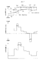
図4に示すように、駆動系制御ユニット32は、バッテリ制御ユニット30から入力される電流Ibatと電圧Vbatとに基づいて駆動用バッテリ34の充放電電力Wbatを算出し、この充放電電力Wbatを積算した電力積算値Ebatを算出する。次いで、算出周期Tpre毎に電力積算値Ebatから電力量変化率である積算値変化率DEbatを算出した後に、この積算値変化率DEbatに基づいて所定の発電量テーブルを参照することにより目標発電量Wgenを設定する。そして、充電状態SOCが下限レベルを下回ることで発電が開始されると、駆動系制御ユニット32は目標発電量Wgenを目標としてエンジン12とジェネレータ21とを制御するようになっている。このように、駆動系制御ユニット32は変化率算出手段、発電量設定手段および発電制御手段として機能することになる。なお、非発電時の算出周期Tpreとしては停止時周期Tev(たとえば10sec)が設定され、発電時の算出周期Tpreとしては停止時周期Tevよりも短い発電時周期Tgen(たとえば2sec)が設定されている。なお、図4はデータの状態を判りやすく説明するため、放電電力が大きい状態での線図であるが、通常の運転時のように、充電電力が大きい状態でも、同様に作用する。以下、駆動系制御ユニット32による発電量設定制御を図5のフローチャートに従って詳細に説明する。
As shown in FIG. 4, the drive
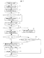
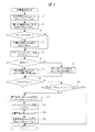
図5に示すように、まずステップS1では、電流Ibatと電圧Vbatとを乗算することによって駆動用バッテリ34の充放電電力Wbatが算出され、ステップS2では充放電電力Wbatをルーチン毎に加算することによって電力積算値Ebatが算出される。そしてステップS3では、カウンタCntが0であるか否かが判定され、カウンタCntが0であると判定された場合には、ステップS4において積算初期値Eintが設定された後に、ステップS5においてカウンタCntがカウント処理される。一方、ステップS3において、カウンタCntが0以外であると判定された場合には、そのままステップS5に進みカウンタCntがカウント処理される。
As shown in FIG. 5, first, in step S1, the charge / discharge power Wbat of the
ステップS6では、ジェネレータ21が発電中であるか否かが判定される。発電状態であると判定された場合には、ステップS7に進み、発電時周期Tgenが算出周期Tpreとして設定される一方、非発電状態つまり停止状態であると判定された場合には、ステップS8に進み、発電時周期Tgenよりも短い停止時周期Tevが算出周期Tpreとして設定される。そして、続くステップS9において、カウンタCntがステップS7またはS8で設定された算出周期Tpreに到達していると判定された場合、つまりルーチンが開始されてから算出周期Tpreを経過した場合には、ステップS10に進み、積算値変化率DEbatが以下の式(1)に基づいて算出される。式(1)に示すように、積算値変化率DEbatは算出周期Tpre内における充放電電力Wbatの電力平均値となっている。
In step S6, it is determined whether or not the
DEbat=(Ebat−Eint)/Cnt・・・・・(1) DEbat = (Ebat−Eint) / Cnt (1)
ステップS10において積算値変化率DEbatが算出されると、ステップS11ではカウンタCntがリセット処理され、続くステップS12では積算値変化率DEbatに基づいて発電量テーブルを参照することにより目標発電量Wgenが設定される。ここで、図6(A)は発電量テーブルの一例を示す特性線図であり、図6(A)に示すように、積算値変化率DEbatが増大する程、つまり駆動用バッテリ34からの放電量が多くなる程、目標発電量Wgenが高く設定されるようになっている。そして、駆動系制御ユニット32は、ジェネレータ21からの発電量が目標発電量Wgenに達するように、エンジン12とジェネレータ21とを制御することになる。なお、ジェネレータ21が停止状態であっても、発電開始判定がなされたときに備えて、積算値変化率DEbatは算出されるようになっている。
When the integrated value change rate DEbat is calculated in step S10, the counter Cnt is reset in step S11, and in the subsequent step S12, the target power generation amount Wgen is set by referring to the power generation amount table based on the integrated value change rate DEbat. Is done. Here, FIG. 6A is a characteristic diagram showing an example of the power generation amount table. As shown in FIG. 6A, as the integrated value change rate DEbat increases, that is, discharge from the
また、前述したステップS9において、カウンタCntが算出周期Tpreを下回ると判定された場合には、ステップS13に進み、駆動用バッテリ34の充放電量(Ebat−Eint)が、所定の下限値Eminと上限値Emaxとの間に収束しているか否かが判定される。ステップS13において、充放電量(Ebat−Eint)が上限値Emaxを上回ると判定された場合や、充放電量(Ebat−Eint)が下限値Eminを下回ると判定された場合には、駆動用バッテリ34の充放電量が急激に変動する状況であるため、ステップS10に進み、算出周期Tpreの経過を待つことなく積算値変化率DEbatが算出され、ステップS12では新たな目標発電量Wgenが設定されることになる。
If it is determined in step S9 that the counter Cnt is less than the calculation cycle Tpre, the process proceeds to step S13, where the charge / discharge amount (Ebat-Eint) of the
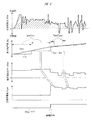
ここで、図7は発電量設定制御における各種データの変動状態を示す線図であり、シリーズ走行モードにおいて運転者がアクセルペダルを踏み込んだ後にアクセルペダルを解放した状況を示している。図7に符号aで示すように、アクセルペダルが踏み込まれ、駆動用バッテリ34からの放電量が増大することにより、充放電量(Ebat−Eint)が上限値Emaxを上回る場合には、予め設定された算出周期Tpreを経過する前であっても、目標発電量Wgenが高く再設定されるとともに、この目標発電量Wgenに基づいて発電制御が実行されることになる。また、符号bで示すように、アクセルペダルが解放されて回生ブレーキが作動することで、駆動用バッテリ34に対する充電量が増大することにより、充放電量(Ebat−Eint)が下限値Eminを下回る場合には、目標発電量Wgenが低く再設定されるとともに、この目標発電量Wgenに基づいて発電制御が実行されることになる。つまり、上限値Emaxや下限値Eminに基づき設定される上限変化率や下限変化率を超えて積算値変化率DEbatが変化した場合には、直ちに算出周期Tpreが短縮されて目標発電量Wgenが再設定されるようになっている。
Here, FIG. 7 is a diagram showing a variation state of various data in the power generation amount setting control, and shows a situation in which the accelerator pedal is released after the driver depresses the accelerator pedal in the series travel mode. As shown by the symbol a in FIG. 7, when the accelerator pedal is depressed and the amount of discharge from the
これまで説明したように、積算値変化率DEbatを算出する際の算出周期Tpreを、ジェネレータ21が発電状態であるか否かによって変化させるようにしたので、発電の開始判定直後に安定した目標発電量Wgenを設定することができ、発電中にあっては走行状況に応じた目標発電量Wgenを的確に設定することができる。つまり、非発電状態にあっては算出周期Tpreを長く設定することにより、長い算出周期Tpreに基づく安定した目標発電量Wgenを発電の開始判定直後に設定することができる一方、発電状態にあっては算出周期Tpreを短く設定することにより、目標発電量Wgenの応答性を向上させることができる。
As described above, the calculation cycle Tpre for calculating the integrated value change rate DEbat is changed depending on whether or not the
また、駆動用バッテリ34の充放電量が急激に変動する場合には、設定された算出周期Tpreの経過を待つことなく、算出周期Tpreを短縮して目標発電量Wgenを更新するようにしたので、走行状況が変化してから目標発電量Wgenを変更するまでの応答性を更に向上させることが可能となる。このように、走行状況に応じて算出周期Tpreを適宜短縮するようにしたので、目標発電量Wgenを大きく変更する必要がない走行状況にあっては、通常の算出周期Tpreに基づいて目標発電量Wgenを設定することにより、目標発電量Wgenの不要な変動を抑制してエンジン効率を向上させることができる。そして、目標発電量Wgenを大きく変更する必要がある走行状況にあっては、算出周期Tpreを短縮させて車両状態の急激な変動に対応させることができ、運転者に良好なフィーリングを与えることが可能となる。
In addition, when the charge / discharge amount of the
また、前述の説明では、積算値変化率DEbatに基づき図6(A)の発電量テーブルを参照することで目標発電量Wgenを設定しているが、これに限られることはなく、積算値変化率DEbatに基づき補正値テーブルを参照することで発電量補正値Cgenを設定するとともに、この発電量補正値Cgenに基づいて目標発電量Wgenを算出するようにしても良い。ここで、図6(B)は補正値テーブルの一例を示す特性線図であり、図6(B)に示すように、積算値変化率DEbatが0を上回って増大する程、つまり駆動用バッテリ34からの放電量が多くなる程に、発電量補正値Cgenが正側に大きく設定される一方、積算値変化率DEbatが0を下回って減少する程、つまり駆動用バッテリ34の充電量が多くなる程に、発電量補正値Cgenが負側に大きく設定されている。
In the above description, the target power generation amount Wgen is set by referring to the power generation amount table in FIG. 6A based on the integrated value change rate DEbat. The power generation amount correction value Cgen may be set by referring to the correction value table based on the rate DEbat, and the target power generation amount Wgen may be calculated based on the power generation amount correction value Cgen. Here, FIG. 6B is a characteristic diagram showing an example of the correction value table. As shown in FIG. 6B, as the integrated value change rate DEbat increases beyond 0, that is, the driving battery. As the amount of discharge from 34 increases, the power generation amount correction value Cgen increases to the positive side, while the integrated value change rate DEbat decreases below 0, that is, the amount of charge of the
図8は発電量設定制御の手順を示すフローチャートである。なお、図5に示すフローチャートと同一のステップについては、同一の符号を付してその説明を省略する。前述したように発電量補正値Cgenを用いて目標発電量Wgenを設定する場合には、図8に示すように、ステップS10で積算値変化率DEbatを算出し、ステップS11でカウンタCntをリセット処理した後に、続くステップS21で積算値変化率DEbatに基づき図6(B)の補正値テーブルを参照して発電量補正値Cgenを設定する。そして、ステップS22において、前回の目標発電量Wgenに発電量補正値Cgenを加算することにより、新たな目標発電量Wgenを設定するようになっている。 FIG. 8 is a flowchart showing a procedure of power generation amount setting control. In addition, about the step same as the flowchart shown in FIG. 5, the same code | symbol is attached | subjected and the description is abbreviate | omitted. As described above, when the target power generation amount Wgen is set using the power generation amount correction value Cgen, as shown in FIG. 8, the integrated value change rate DEbat is calculated in step S10, and the counter Cnt is reset in step S11. Thereafter, in step S21, the power generation amount correction value Cgen is set with reference to the correction value table of FIG. 6B based on the integrated value change rate DEbat. In step S22, a new target power generation amount Wgen is set by adding the power generation amount correction value Cgen to the previous target power generation amount Wgen.
つまり、積算値変化率DEbatが正側に算出され駆動用バッテリ34が放電状態となる場合には、目標発電量Wgenが前回よりも大きな値に補正される一方、積算値変化率DEbatが負側に算出され駆動用バッテリ34が充電状態となる場合には、目標発電量Wgenが前回よりも小さな値に補正されることになる。また、ステップS22では、前回の目標発電量Wgenを補正して新たな目標発電量Wgenを算出するようにしているが、これに限られることはなく、補正の基準となる基本発電量を予め設定しておき、この基本発電量を発電量補正値Cgenによって補正することで新たな目標発電量Wgenを算出しても良い。
That is, when the integrated value change rate DEbat is calculated on the positive side and the
このように、発電量補正値Cgenを用いて目標発電量Wgenを設定することにより、目標発電量Wgenの急激な変動することを抑制できるため、エンジン12の駆動状態を安定させてエンジン効率を高めることができるとともに、運転者に良好なフィーリングを与えることができる。
In this way, by setting the target power generation amount Wgen using the power generation amount correction value Cgen, it is possible to suppress a rapid fluctuation of the target power generation amount Wgen, so that the driving state of the
本発明は前記実施の形態に限定されるものではなく、その要旨を逸脱しない範囲で種々変更可能である。たとえば、本発明の発電制御装置は、前輪駆動のハイブリッド車両に適用されているが、これに限られることはなく、後輪駆動や4輪駆動のハイブリッド車両に適用しても良い。また、シリーズ・パラレル方式のハイブリッド車両に限られることはなく、シリーズ方式のハイブリッド車両に本発明を適用しても良い。さらに、エンジン動力の伝達経路に変速機構を設けるようにしたハイブリッド車両に本発明を適用しても良い。 The present invention is not limited to the above-described embodiment, and various modifications can be made without departing from the scope of the invention. For example, the power generation control device of the present invention is applied to a front-wheel drive hybrid vehicle, but is not limited thereto, and may be applied to a rear-wheel drive or four-wheel drive hybrid vehicle. Further, the present invention is not limited to a series / parallel type hybrid vehicle, and the present invention may be applied to a series type hybrid vehicle. Further, the present invention may be applied to a hybrid vehicle in which a transmission mechanism is provided in the engine power transmission path.
また、前述の説明では、充放電電力Wbatを電力積算値Ebatに置き換え、電力積算値Ebatの積算値変化率DEbatから目標発電量Wgenを設定しているが、これに限られることはなく、充放電電力Wbatから直接的に算出周期Tpre内での電力量変化率を算出して、この電力量変化率に基づき目標発電量Wgenを設定しても良い。 In the above description, the charge / discharge power Wbat is replaced with the integrated power value Ebat, and the target power generation amount Wgen is set from the integrated value change rate DEbat of the integrated power value Ebat. However, the present invention is not limited to this. The power amount change rate within the calculation cycle Tpre may be calculated directly from the discharge power Wbat, and the target power generation amount Wgen may be set based on this power amount change rate.
なお、変化率算出手段、発電量設定手段、発電制御手段として駆動系制御ユニット32を機能させているが、駆動系制御ユニット32に限られることはなく、他の制御ユニットを変化率算出手段、発電量設定手段、発電制御手段として機能させても良い。
The drive
11 駆動モータ(電動モータ)
12 エンジン
21 ジェネレータ(発電機)
32 駆動系制御ユニット(変化率算出手段,発電量設定手段,発電制御手段)
34 駆動用バッテリ(蓄電手段)
DEbat 積算値変化率(電力量変化率)
Tpre 算出周期(所定周期)
Wgen 目標発電量
Cgen 発電量補正値
11 Drive motor (electric motor)
12
32 Drive system control unit (change rate calculation means, power generation amount setting means, power generation control means)
34 Drive battery (power storage means)
DEbat integrated value change rate (electric energy change rate)
Tpre calculation cycle (predetermined cycle)
Wgen Target power generation
Cgen Power generation correction value
Claims (4)
前記発電機からの電力を蓄え、前記電動モータに電力を供給する蓄電手段と、
前記蓄電手段の電力量変化率を所定周期毎に算出する変化率算出手段と、
前記電力量変化率に基づいて目標発電量を設定する発電量設定手段と、
前記目標発電量に基づいて前記発電機を制御する発電制御手段とを有し、
前記所定周期を車両状態に基づいて変化させることを特徴とするハイブリッド車両の発電制御装置。 A power generation control device for a hybrid vehicle having an engine for driving a generator and an electric motor for driving drive wheels,
Power storage means for storing power from the generator and supplying power to the electric motor;
A rate-of-change calculating means for calculating a rate of change in the amount of electric power of the power storage means for each predetermined period;
A power generation amount setting means for setting a target power generation amount based on the power amount change rate;
Power generation control means for controlling the generator based on the target power generation amount,
A power generation control device for a hybrid vehicle, wherein the predetermined cycle is changed based on a vehicle state.
The power generation control device for a hybrid vehicle according to any one of claims 1 to 3, wherein the power generation amount setting means sets a power generation amount correction value based on the power amount change rate, and sets the power generation amount correction value. A power generation control device for a hybrid vehicle, wherein a target power generation amount is set using the power generation control device.
Priority Applications (1)
| Application Number | Priority Date | Filing Date | Title |
|---|---|---|---|
| JP2004103630A JP2005295618A (en) | 2004-03-31 | 2004-03-31 | Power generation control device for hybrid vehicle |
Applications Claiming Priority (1)
| Application Number | Priority Date | Filing Date | Title |
|---|---|---|---|
| JP2004103630A JP2005295618A (en) | 2004-03-31 | 2004-03-31 | Power generation control device for hybrid vehicle |
Publications (1)
| Publication Number | Publication Date |
|---|---|
| JP2005295618A true JP2005295618A (en) | 2005-10-20 |
Family
ID=35327956
Family Applications (1)
| Application Number | Title | Priority Date | Filing Date |
|---|---|---|---|
| JP2004103630A Pending JP2005295618A (en) | 2004-03-31 | 2004-03-31 | Power generation control device for hybrid vehicle |
Country Status (1)
| Country | Link |
|---|---|
| JP (1) | JP2005295618A (en) |
-
2004
- 2004-03-31 JP JP2004103630A patent/JP2005295618A/en active Pending
Similar Documents
| Publication | Publication Date | Title |
|---|---|---|
| JP3613216B2 (en) | Control device for hybrid vehicle | |
| EP1129889B1 (en) | Regeneration control device of hybrid electric vehicle | |
| US7108088B2 (en) | Hybrid vehicle and control method of hybrid vehicle | |
| JP6168031B2 (en) | vehicle | |
| JP5949731B2 (en) | Hybrid vehicle | |
| JP5304350B2 (en) | Vehicle control device | |
| US9923490B2 (en) | Vehicle | |
| JP4217192B2 (en) | Control device for hybrid vehicle | |
| WO2007141984A1 (en) | Controller of hybrid vehicle and hybrid vehicle | |
| JP2019069733A (en) | Hybrid vehicle control device | |
| CN110871785B (en) | Hybrid Vehicle Controls | |
| JP5598555B2 (en) | Vehicle and vehicle control method | |
| JP2007239511A (en) | Vehicle drive control device | |
| US20090163317A1 (en) | Power Output Apparatus, Vehicle Provided With the Same, and Method of Controlling the Same | |
| JP6414111B2 (en) | Display device | |
| JP6414112B2 (en) | Display device | |
| JP2009126303A (en) | Vehicle control unit | |
| US20150291161A1 (en) | Cruise control apparatus | |
| JP2013220682A (en) | Hybrid vehicle | |
| WO2012101798A1 (en) | Vehicle, and vehicle control method | |
| JP2011097666A (en) | Vehicle and control method therefor | |
| JP2006312352A (en) | Control device for drive system | |
| JP2017103980A (en) | Vehicular regeneration control apparatus | |
| JP2012016972A (en) | Hybrid automobile | |
| JP2005295617A (en) | Power generation control device for hybrid vehicle |