JP2005295594A - Millimeter-wave band wireless communication system - Google Patents
Millimeter-wave band wireless communication system Download PDFInfo
- Publication number
- JP2005295594A JP2005295594A JP2005157406A JP2005157406A JP2005295594A JP 2005295594 A JP2005295594 A JP 2005295594A JP 2005157406 A JP2005157406 A JP 2005157406A JP 2005157406 A JP2005157406 A JP 2005157406A JP 2005295594 A JP2005295594 A JP 2005295594A
- Authority
- JP
- Japan
- Prior art keywords
- wave
- frequency
- local oscillation
- signal
- millimeter
- Prior art date
- Legal status (The legal status is an assumption and is not a legal conclusion. Google has not performed a legal analysis and makes no representation as to the accuracy of the status listed.)
- Withdrawn
Links
Images
Abstract
Description
本発明はマイクロ波帯・ミリ波帯の無線通信装置に関する。 The present invention relates to a wireless communication device of microwave band / millimeter wave band.
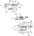
まず、第1の従来例として、非特許文献1に開示されているミリ波送受信機の構成を図5に示す。 First, as a first conventional example, the configuration of a millimeter wave transceiver disclosed in Non-Patent Document 1 is shown in FIG.
図5(a)に示す送信側においては、IF変調信号源100によって変調された中間周波数信号108aと、局部発振器105により発振された局部発振波106が、周波数ミキサ101に入力されて周波数上昇変換され、周波数上昇変換された無線信号波107のみがバンドパスフィルタ102により取り出され、送信用増幅器103により、適当なレベルまで増幅されてアンテナ104にて放射される。
On the transmission side shown in FIG. 5 (a), the
図5(b)は、局部発振波106と無線信号波107の周波数の位置関係を示す図である。
FIG. 5B is a diagram showing the positional relationship between the frequency of the
図5(c)に示す受信側においては、アンテナ112により受信した信号波が低雑音アンプ111で適当なレベルまで増幅され、バンドパスフィルタ102で、所望波である無線信号波107のみが取り出されて周波数ミキサ110に入力される。同時に受信側で生成した局部発振器114で発生させた局部発振波105も周波数ミキサ110に入力される。周波数ミキサでは、周波数ダウンコンバートされ中間周波数信号108bが生成される。
On the receiving side shown in FIG. 5C, the signal wave received by the
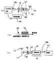
次に、第2の従来のミリ波帯通信装置として、非特許文献2,3に開示されているミリ波自己ヘテロダイン通信システムについて、図6(a)〜(c)に示す。第1の従来例と同様な動作・機能するものは同じ番号で示している。 Next, as a second conventional millimeter wave band communication device, a millimeter wave self-heterodyne communication system disclosed in Non-Patent Documents 2 and 3 is shown in FIGS. Components that operate and function in the same manner as in the first conventional example are indicated by the same numbers.
図6(a)に示す送信側においては、IF変調信号源100によって、変調された中間周波数信号108aが生成され、局部発振器105により局部発振波106が生成され、当該局部発振波106が周波数ミキサ101に入力されて周波数上昇変換され、周波数上昇変換された無線信号波107と局部発振波106がバンドパスフィルタ102により取り出され、送信用増幅器103により、適当なレベルまで増幅されてアンテナ104にて放射される。
6A, the IF modulated
受信側においては、アンテナ112により受信した信号が低雑音アンプ111で適当なレベルまで増幅され、バンドパスフィルタ102で、所望波である無線信号波107と局部発振波106が取り出されて周波数ミキサ110に入力される。周波数ミキサのもつ2乗効果によって、前記無線信号波107と局部発信波106は2乗検波され、受信側で中間周波数信号108bが生成されて復調器113へ入力される。
図5の第1の従来例においては、30GHz以上のミリ波帯では、送信側の局部発振器105、受信機側の局部発振器114に高い周波数安定度を持たせるのが困難であり、かつ、発振器の位相雑音が大きく、変調信号が4相以上の多値位相変調方式やマルチキャリ方式(OFDM)伝送方式でのディジタル無線通信が困難であるという課題があった。
In the first conventional example of FIG. 5, in the millimeter wave band of 30 GHz or more, it is difficult to give high frequency stability to the
一方、第2の従来例のように、変調信号波と局部発振波を同時に伝送し、受信側の周波数ミキサ110において2乗検波するような方式では、ミリ波局部発振器105の安定度と位相雑音は周波数ミキサ110でキャンセルされるため、上記発振器に対する課題は解決される。
On the other hand, as in the second conventional example, in a system in which a modulated signal wave and a local oscillation wave are transmitted simultaneously and square detection is performed at the
しかしながら、以下に述べる理由により、第2の従来例では、第1の従来例に比較して、無線伝送距離が短くなってしまうという新たな問題が発生する。 However, for the reason described below, the second conventional example has a new problem that the wireless transmission distance becomes shorter than that of the first conventional example.
図5に示す第1の従来例においては、受信側周波数ミキサでは、周波数ダウンコンバートされ中間周波数信号108bが生成される。ここで、受信側の局部発振器114の出力パワーは一定であり、入力された無線信号波107と、変換された中間周波信号108bの関係は、線形関係にあり、無線信号波が6dB減衰すれば、出力される中間周波数信号も6dB減衰する関係にある。
In the first conventional example shown in FIG. 5, the reception-side frequency mixer performs frequency down-conversion to generate an
これに対して図6に示すような第2の従来例においては、局部発振波106と無線信号波107が無線区間を伝送するため、無線伝送区間距離が長くなる距離の2乗に反比例して、局部発振波106と無線信号波107電力は減衰する。つまり局部発振波106と無線信号波107の電力は夫々無線伝送距離が2倍になると、6dBずつ劣化する。従って、受信器中の周波数ミキサ110は、2乗検波特性を使用するために、距離が2倍になると12dBずつ減衰する。この減衰は第1の従来例に比較して2倍である。
On the other hand, in the second conventional example as shown in FIG. 6, since the
以上述べたように、第2の従来例では第1の従来例に比較して、減衰が2倍になり、その結果、無線伝送距離が少なくとも1/2となってしまうという問題があった。 As described above, the second conventional example has a problem that the attenuation is doubled as compared with the first conventional example, and as a result, the wireless transmission distance is at least ½.
加えて、第2の従来例では、略同一パワーの無線信号波107と局部発振波106である必要があり、無線信号波は通常数MHz〜100MHzの広帯域信号であり、局部発振信号波は正弦波であり、帯域幅は1kHz以下である。従って、無線信号波107と局部発振波106の信号波を同一のパワーで無線伝送しようとすると、局部発振波の方が、単位帯域当たりの平均パワーが著しく大きくなり送信用増幅器103が歪やすくなる。従って、線形性の高い送信アンプが必要になる、あるいは、アンプの線形動作領域まで全体の送信パワーを下げて伝送しなければならず、さらに伝送距離が短くなるという問題があった。
In addition, in the second conventional example, it is necessary that the
本発明の目的は、こうした無線伝送距離と、発振器の安定性・位相雑音特性の課題を解決し、無線伝送距離を確保しつつ安定で位相雑音特性にすぐれたミリ波帯無線通信装置を提供することにある。 SUMMARY OF THE INVENTION An object of the present invention is to provide a millimeter-wave band wireless communication apparatus that solves such problems of wireless transmission distance and stability / phase noise characteristics of an oscillator, and that is stable and has excellent phase noise characteristics while ensuring the wireless transmission distance. There is.
本発明のミリ波帯無線通信装置は、送信側で、変調信号波と低周波局部発振信号波の多重波である信号波を、送信側局部発振波を用いてミリ波帯へ周波数上昇変換し、前記周波数上昇変換された信号波を送信し、受信側で、送信されてきた、前記周波数上昇変換された信号波に含まれる低周波局部発振信号波に同期して受信側局部発振波を再生し、再生された前記受信側局部発振波を用いて前記周波数上昇変換された信号波を周波数下降変換して信号波を生成することを特徴とする。 The millimeter-wave band wireless communication apparatus of the present invention converts a signal wave, which is a multiplexed wave of a modulated signal wave and a low-frequency local oscillation signal wave, into a millimeter-wave band using the transmission-side local oscillation wave on the transmission side. The signal wave having been subjected to the frequency rise conversion is transmitted, and the reception side local oscillation wave is reproduced in synchronization with the low frequency local oscillation signal wave included in the signal wave having undergone the frequency rise conversion transmitted on the reception side. Then, the signal wave that has been frequency-up-converted using the reproduced reception-side local oscillation wave is frequency-down-converted to generate a signal wave.
前記受信側局部発振波を再生する再生回路に注入同期発振器を具備することが好ましい。 It is preferable to provide an injection locked oscillator in the reproduction circuit for reproducing the reception side local oscillation wave.
または、前記受信側局部発振波を再生する再生回路に自励発振ミキサを具備することが好ましい。 Alternatively, it is preferable to provide a self-excited oscillation mixer in a reproduction circuit that reproduces the reception-side local oscillation wave.
あるいは、前記受信側局部発振波を再生する再生回路に位相同期発振器を具備することが好ましい。 Alternatively, it is preferable that the reproduction circuit that reproduces the reception-side local oscillation wave includes a phase-locked oscillator.
さらに、前記受信側局部発振波を再生する再生回路にミリ波増幅器を具備することが好ましい。 Furthermore, it is preferable that the reproduction circuit for reproducing the reception-side local oscillation wave includes a millimeter wave amplifier.
(実施の形態1)
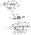
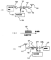
図1に本発明の構成を示す。第1の従来例と同様な動作・機能するものは同一番号で示す。送信側の構成は図1(a)に示すように変調信号源100によって、変調された中間周波数信号108aが生成され、ミリ波帯局部発振器105により局部発振波106が生成され、当該局部発振波106が周波数変換器101に入力されて周波数上昇変換され、周波数上昇変換された無線信号波107と局部発振波106が通過帯域フィルタ1により取り出され、送信用増幅器103により、適当なレベルまで増幅されてアンテナ104にて放射される。図1(b)は局部発振波106と無線信号波107の関係を示す図である。
(Embodiment 1)
FIG. 1 shows the configuration of the present invention. The same operations and functions as those in the first conventional example are indicated by the same numbers. As shown in FIG. 1 (a), the transmission side is configured such that a modulated
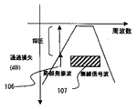
ここで、図2に通過帯域フィルタ1の特性を示す。無線信号波107は、通過帯域となっており、局部発振波は一部の信号が抑圧される。無線信号波107のトータルパワーよりも、局部発振波のトータルパワーは、3dB以上小さくコントロールされている。これによって送信アンプ103が局部発振波106で飽和されることを防いでいる。
Here, the characteristics of the passband filter 1 are shown in FIG. The
一方受信側では、図1(c)に示すように、アンテナ112により受信した信号が低雑音アンプ111で適当なレベルまで増幅される。分配器6で信号は2分配され、無線信号波107はバンドパスフィルタ200で、帯域通過させ、一方局部発振波106の方はバンドパスフィルタ3により、局部発振波のみを帯域通過させる。該帯域通過した局部発振波106は、適当なレベルまで増幅器4により増幅された後、注入同期発振器5に入力される。
On the other hand, on the receiving side, as shown in FIG. 1C, the signal received by the
局部発振波106の信号で当該注入同期発振器5を同期させ、送信側の局部発振波106を再生させる。該同期信号波は、一定の出力を有しており、局部発振波50aとなる。該局部発振波50aは、周波数ミキサ110に入力され、局部発振信号波50aで、無線周波数信号波107は、周波数ダウンコンバートされ、中間周波信号108bを生成する。当該中間周波信号108bは、復調器113へ入力される構成となる。
The injection locking oscillator 5 is synchronized with the signal of the
該注入同期発振器5の同期幅が、通常数10MHz以上であり、局部発振信号106の帯域幅(1kHz以下)に比較して、局部発振同期信号50aは、十分に狭いため、送信側の局部発振器105の周波数と位相に同期し、送信側の局部発振波106が再生される。従って、該ダウンコンバートされた中間周波信号108bは、ミリ波帯局部発振器105の周波数安定性、位相雑音の影響は受けず、受信側周波数ミキサ110内部では、局部発振器の周波数安定性と位相雑音は、ほぼ完全にキャンセルされる。
The synchronization width of the injection locking oscillator 5 is usually several tens of MHz or more, and the local oscillation synchronization signal 50a is sufficiently narrow compared to the bandwidth (1 kHz or less) of the
つまり、送信側の無線信号波107の周波数fRFは、次式(1)で表される。
fRF=(fLO+ΔfLO)+fIFa …(1)
ただし、fLOは送信側の局部発振信号106の周波数であり、ΔfLOは周波数不安定性にもとづく局部発振信号の周波数変動分であり、fIFaは送信側の中間周波信号108aの周波数である。また、無線信号波107の周波数fRFには、局部発振器105の周波数変動ΔfLOが含まれている。
That is, the frequency fRF of the
fRF = (fLO + ΔfLO) + fIFa (1)
However, fLO is the frequency of the
一方、受信側のダウンコンバートされた中間周波信号108bの周波数fIFbは、次式(2)で表される。
On the other hand, the frequency fIFb of the down-converted
fIFb=fRF−(fLO+ΔfLO)=fIFa …(2)
したがって、周波数変動成分は送受間で完全にキャンセルされる。加えて、位相も同期しているため同期した局部発振波は、位相の揺らぎ成分(位相雑音成分)も、送信側と受信側では同期がとれ、同じ位相角となり、受信側でダウンコンバート時には、位相雑音成分もキャンセルされてしまう。
fIFb = fRF− (fLO + ΔfLO) = fIFa (2)
Therefore, the frequency variation component is completely canceled between transmission and reception. In addition, since the phase is also synchronized, the synchronized local oscillation wave, the phase fluctuation component (phase noise component) is also synchronized on the transmission side and the reception side, the same phase angle, and at the time of down-conversion on the reception side, The phase noise component is also canceled.
加えて、受信側の注入同期発振器5の出力パワーは一定であり、入力された無線信号波107と、変換された中間周波信号108bの関係は、線形関係にあり、無線信号波が6dB減衰すれば、出力される中間周波信号も6dB減衰する関係にある。つまり、第2の従来例のような少なくとも12dB減衰する関係になく、伝送距離が短くなることを防ぐことが可能となる。
In addition, the output power of the injection locking oscillator 5 on the receiving side is constant, and the relationship between the input
ここでは中間周波信号源として変調信号波を発生する変調信号源100を用いて説明したが、当該信号波は、TVの無線信号、CATVの伝送信号、衛星放送の中間周波信号であってもよい。同時に、受信側の復調器113は、地上波・CATV・衛星放送用TVチューナであっても構わない。
Here, the
上記の構成で、注入同期発振器5の代わりに増幅器を用いて多重波中の局部発振波106を再生しても構わない。
With the above configuration, the
さらに、上記の構成では、送信側の局部発振器105からの信号を局部発振信号波106としたが、場合によっては、送信側の中間周波数の中間周波数信号108aを、変調信号波と低周波局部発振波の多重波で構成し、当該中間周波数の多重信号波が、ミリ波帯へ周波数上昇変換されたミリ波無線多重波信号波が送信され、受信側で、ミリ波帯へ上昇変換された局部発振波成分に同期した信号波が増幅・再生されてミリ波局部発振信号波50aとなり、周波数ミキサ110で周波数ダウンコンバータされて周波数下降変換されて、中間周波数の中間周波信号108bを生成しても構わない。この場合、送信側のミリ波局部発振波106はバンドパスフィルタ200で抑圧されている。
Furthermore, in the above configuration, the signal from the
(実施の形態2)
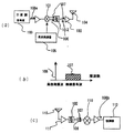
第2の実施形態を図3(a)〜(c)に示す。第1の実施形態とは図3(a)に示す送信側の構成,図3(b)に示す局部発振波106、無線信号波107の関係は同じであり、受信側のみが異なるので、この異なる部分を説明する。
(Embodiment 2)
A second embodiment is shown in FIGS. The configuration of the transmission side shown in FIG. 3A and the relationship between the
第1の実施の形態では、周波数ミキサ110と周波数再生手段2aを注入同期発振器で構成した例で示したが、第2の実施形態では、周波数ミキサを自励発振ミキサ20で構成する。動作は、アンテナより受信した局部発振波106と無線信号波107を低雑音アンプ111で適当なレベルまで増幅し局部発振波106と無線信号波107を通過帯域フィルタ102で取り出し、自励発振ミキサ20に入力される。該自励発振ミキサとして、例えば、IEEE−S Int.Microwave Symp.Dig.,1998,pp.1135−1138に示されているSelf−Oscillating Mixersを利用することができる。
In the first embodiment, the example in which the
当該自励発振ミキサ20は、送信側の局部発振周波数106付近で自由発振しており、当該自励発振ミキサ20を受信機への入力された局部発振信号波106で同期する構成である。該当該自励発振ミキサ20を受信機への入力された局部発振信号波106で注入同期をとると同時に、入力無線信号波107の信号波で周波数混合され、ダウンコンバートされた中間周波信号108bを生成する構成である。
The self-oscillation mixer 20 oscillates freely near the
当該中間周波信号108bは、復調器113へ入力される構成となる。この場合も第1の実施形態と同様に、該ダウンコンバートされた中間周波信号108bは、ミリ波発振器105の周波数安定性、位相雑音の影響は受けず、受信側の自励発振周波数ミキサ20内部では、ほぼ完全にキャンセルされる。
The
加えて、受信側の自励発振器20の出力パワーは一定であり、入力された無線信号波107と、変換された中間周波信号108bの関係は、線形関係にあり、無線信号波107が6dB減衰すれば、出力される中間周波信号108bも6dB減衰する関係にあり、第2の従来例のような少なくとも12dB減衰する関係になく、伝送距離が短くなることも防ぐことが可能となる。
In addition, the output power of the self-excited oscillator 20 on the receiving side is constant, and the relationship between the input
(実施の形態3)
第3の実施形態を図4(a)〜(c)に示す。第1の実施形態とは図4(a)に示す送信側の構成,図4(b)に示す局部発振波106、無線信号波107の関係は同じであり、受信側のみが異なるので、この異なる部分のみ説明する。
(Embodiment 3)
A third embodiment is shown in FIGS. The configuration of the transmission side shown in FIG. 4A and the relationship between the
第1の実施の形態では、周波数ミキサ110と第1の周波数再生手段2aを注入同期発振器5で構成した例で示したが、第3の実施形態では、第2の周波数再生手段2bとして、位相同期発振器2bが構成される。
In the first embodiment, the example in which the
動作は、アンテナにより受信した局部発振波106と無線信号波107を適当なレベルまで増幅し、分配器6で2分配し、無線信号波107のみをバンドパスフィルタ200で、帯域通過し、一方局部発振波106の方は、当該信号波106のみをバンドパスフィルタ3により、帯域通過させ、適当なレベルまで増幅器4により増幅した後、位相比較器10に入力させる。
In operation, the
一方送信側の局部発振周波数106付近で自由発振している電圧制御発振器12の信号の一部が位相比較器10に入力される。この位相比較器10は誤差信号15を生成し、ループフィルタにより帯域制限と位相制御されたあと電圧制御発振器12へ入力することによって位相同期ループを構成する。当該位相同期ループにより、電圧制御発振器12は受信器に入力された局部発振波106に位相同期し、周波数と位相は完全に同期する。当該同期信号波50bは一定の出力を有しており、周波数ミキサ110に入力され、当該局部発振信号波50bで、周波数ダウンコンバートされ、中間周波信号108を生成する。当該中間周波信号108bは、復調器113へ入力される構成となる。
On the other hand, a part of the signal of the voltage controlled
該ダウンコンバートされた中間周波信号108bは、送信側の局部発振器105の周波数安定性、位相雑音の影響は受けず、受信側周波数ミキサ110内部では、ほぼ完全にキャンセルされる。
The down-converted
加えて、受信側の位相同期発振器2bからの出力信号50bの出力パワーは一定であり、入力された無線信号波107と、変換された中間周波信号108bの関係は、線形関係にあり、無線信号波107が6dB減衰すれば、出力される中間周波信号も6dB減衰する関係にあり、第2の従来例のような少なくとも12dB減衰する関係になく、伝送距離が短くなることも防ぐことが可能となる。
In addition, the output power of the
以上のように、この発明によれば、受信装置側で、送信装置の局部発振器に同期した信号を再生して周波数ダウンコンバートするので、受信装置からの出力信号中間周波信号は、送信側の局部発振器の周波数安定性、位相雑音の影響は受けず、受信側周波数ミキサ内部では、ほぼ完全にキャンセルされる。 As described above, according to the present invention, since the signal synchronized with the local oscillator of the transmitting device is reproduced and frequency down-converted on the receiving device side, the output signal intermediate frequency signal from the receiving device is It is not affected by the frequency stability and phase noise of the oscillator, and is almost completely canceled inside the receiving frequency mixer.
また、受信側の位相同期発振器からの出力パワーは一定であり、入力された無線信号波と、変換された中間周波信号の関係は、線形関係にあり、無線信号波が6dB減衰すれば、出力される中間周波信号も6dB減衰する関係にあり、第2の従来例のような少なくとも12dB減衰する関係になく、伝送距離が短くなることも防ぐことが可能となる。 Also, the output power from the phase-locked oscillator on the receiving side is constant, and the relationship between the input radio signal wave and the converted intermediate frequency signal is linear, and if the radio signal wave attenuates by 6 dB, the output The intermediate frequency signal is also attenuated by 6 dB and is not attenuated by at least 12 dB as in the second conventional example, and it is possible to prevent the transmission distance from being shortened.
加えて、送信側の局部発振波の出力を制御しているために、送信アンプの歪を少なくでき、より長距離伝送が可能となる。以上のように、当該ミリ波通信装置は、受信側でミリ波局部発振波再生手段を有しているため、無線伝送に対して周波数安定度と位相雑音特性に関して厳しい性能が要求される地上波ディジタル放送等に使用されているOFDM伝送やCATV等で使用されている64QAM〜256QAMの多値変調波信号に対してもミリ波無線接続することが可能となる。 In addition, since the output of the local oscillation wave on the transmission side is controlled, the distortion of the transmission amplifier can be reduced and transmission over a longer distance is possible. As described above, since the millimeter wave communication apparatus has the millimeter wave local oscillation wave reproducing means on the receiving side, terrestrial waves that require strict performance with respect to frequency stability and phase noise characteristics for wireless transmission. It is possible to make a millimeter wave wireless connection even for multi-level modulation wave signals of 64QAM to 256QAM used in OFDM transmission and CATV used in digital broadcasting and the like.
1 バンドパスフィルタ、2a 第1の周波数再生手段、2b 第2の周波数再生手段、3 バンドパスフィルタ、4 増幅器、5 注入同期発振器、6 分配器、12 電圧制御発振器、13 増幅器、15 誤差信号、20 自励発振ミキサ(セルフオシレーティングミキサ)、50a 局部発振波、50b 同期信号波、100 変調信号源、101 周波数変換器、102 バンドパスフィルタ、103 送信アンプ、104 送信アンテナ、105 局部発振器、106 局部発振波、107 無線信号、108b 中間周波信号、110 周波数ミキサ、112 受信アンテナ、113 復調器、200 バンドパスフィルタ。 DESCRIPTION OF SYMBOLS 1 Band pass filter, 2a 1st frequency reproduction | regeneration means, 2b 2nd frequency reproduction | regeneration means, 3 Band pass filter, 4 Amplifier, 5 Injection-locking oscillator, 6 Divider, 12 Voltage controlled oscillator, 13 Amplifier, 15 Error signal, 20 self-oscillation mixer (self-oscillating mixer), 50a local oscillation wave, 50b synchronization signal wave, 100 modulation signal source, 101 frequency converter, 102 bandpass filter, 103 transmission amplifier, 104 transmission antenna, 105 local oscillator, 106 Local oscillation wave, 107 radio signal, 108b intermediate frequency signal, 110 frequency mixer, 112 receiving antenna, 113 demodulator, 200 band pass filter.
Claims (5)
Priority Applications (1)
| Application Number | Priority Date | Filing Date | Title |
|---|---|---|---|
| JP2005157406A JP2005295594A (en) | 2005-05-30 | 2005-05-30 | Millimeter-wave band wireless communication system |
Applications Claiming Priority (1)
| Application Number | Priority Date | Filing Date | Title |
|---|---|---|---|
| JP2005157406A JP2005295594A (en) | 2005-05-30 | 2005-05-30 | Millimeter-wave band wireless communication system |
Related Parent Applications (1)
| Application Number | Title | Priority Date | Filing Date |
|---|---|---|---|
| JP2000320188A Division JP3745610B2 (en) | 2000-10-20 | 2000-10-20 | Millimeter-wave wireless communication method |
Publications (1)
| Publication Number | Publication Date |
|---|---|
| JP2005295594A true JP2005295594A (en) | 2005-10-20 |
Family
ID=35327935
Family Applications (1)
| Application Number | Title | Priority Date | Filing Date |
|---|---|---|---|
| JP2005157406A Withdrawn JP2005295594A (en) | 2005-05-30 | 2005-05-30 | Millimeter-wave band wireless communication system |
Country Status (1)
| Country | Link |
|---|---|
| JP (1) | JP2005295594A (en) |
Cited By (1)
| Publication number | Priority date | Publication date | Assignee | Title |
|---|---|---|---|---|
| CN101902235A (en) * | 2009-05-29 | 2010-12-01 | 索尼公司 | Demodulator and communicator |
-
2005
- 2005-05-30 JP JP2005157406A patent/JP2005295594A/en not_active Withdrawn
Cited By (3)
| Publication number | Priority date | Publication date | Assignee | Title |
|---|---|---|---|---|
| CN101902235A (en) * | 2009-05-29 | 2010-12-01 | 索尼公司 | Demodulator and communicator |
| JP2010278896A (en) * | 2009-05-29 | 2010-12-09 | Sony Corp | Demodulator and communication apparatus |
| US8310303B2 (en) | 2009-05-29 | 2012-11-13 | Sony Corporation | Demodulator and communication apparatus |
Similar Documents
| Publication | Publication Date | Title |
|---|---|---|
| JP3619387B2 (en) | Measuring receiver | |
| JP3753518B2 (en) | Tuner for cable modem | |
| JP3564480B2 (en) | Wireless communication method and system for performing communication between a plurality of wireless communication terminals | |
| JP2001053640A (en) | Device and method for radio communication | |
| KR20060134916A (en) | Radio receiver and radio transmitter | |
| US20070149143A1 (en) | Local oscillation frequency generation apparatus and wireless transceiver having the same | |
| US9319081B2 (en) | Communication device with improved interference rejection and a method thereof | |
| US6370361B1 (en) | Transceiver with a receive/transmit fast switch function | |
| EP2048775A1 (en) | Anti jamming system | |
| JP2005287065A (en) | Millimeter band communication device | |
| JP2000151553A (en) | Signal transmitteir | |
| US6813326B1 (en) | Data transmission system, data transmission communication station, and data transmission method | |
| US20050249265A1 (en) | Method and system for frequency hopping radio communication | |
| US7076217B1 (en) | Integrated radio transceiver | |
| JP2005295594A (en) | Millimeter-wave band wireless communication system | |
| JP3745610B2 (en) | Millimeter-wave wireless communication method | |
| JP2003318761A (en) | Reception control method, reception control device and receiver | |
| KR101233763B1 (en) | Wideband phase shift device | |
| US20120282866A1 (en) | Radio transceiver architecture | |
| JP2009094958A (en) | Retransmitting device and retransmission method | |
| JP3598378B2 (en) | Wireless communication method and system | |
| KR100947469B1 (en) | Method and system for frequency hopping radio communication | |
| KR0140678B1 (en) | Satellite broadcasting repeator | |
| JP2003273818A (en) | Apparatus and method for converting frequency | |
| KR100344108B1 (en) | Translator for minimizing BER of Ponit to Multi-Point transmission on millimeter wave |
Legal Events
| Date | Code | Title | Description |
|---|---|---|---|
| A300 | Withdrawal of application because of no request for examination |
Free format text: JAPANESE INTERMEDIATE CODE: A300 Effective date: 20080108 |