JP2005295584A - Editing method and editing apparatus - Google Patents
Editing method and editing apparatus Download PDFInfo
- Publication number
- JP2005295584A JP2005295584A JP2005136516A JP2005136516A JP2005295584A JP 2005295584 A JP2005295584 A JP 2005295584A JP 2005136516 A JP2005136516 A JP 2005136516A JP 2005136516 A JP2005136516 A JP 2005136516A JP 2005295584 A JP2005295584 A JP 2005295584A
- Authority
- JP
- Japan
- Prior art keywords
- data
- editing
- video
- edit list
- unit
- Prior art date
- Legal status (The legal status is an assumption and is not a legal conclusion. Google has not performed a legal analysis and makes no representation as to the accuracy of the status listed.)
- Granted
Links
Images
Landscapes
- Management Or Editing Of Information On Record Carriers (AREA)
- Television Signal Processing For Recording (AREA)
- Signal Processing For Digital Recording And Reproducing (AREA)
Abstract
【課題】 編集効率の向上を図ることを課題とする。
【解決手段】 カメラ部100と、テープ状記録媒体160を用いる第1の記録部150と、撮像映像信号を圧縮する信号処理部200と、この出力を非テープ状記録媒体260に記録する第2の記録部250と、制御部120と、情報を付加する情報付加部140とからなるカメラ一体型記録装置300と、上記非テープ状記録媒体260を用いてエディットリストを作成するための第1の編集システム400と、非テープ状記録媒体380から読み込んだエディットリストに基いて、再生装置500を制御し、目的とする素材を再生するための編集機450と、再生装置500とからなる第2の編集システム550とで構成される。
【選択図】 図1
[PROBLEMS] To improve editing efficiency.
A camera unit 100, a first recording unit 150 using a tape-shaped recording medium 160, a signal processing unit 200 for compressing an imaged video signal, and a second for recording this output on a non-tape-shaped recording medium 260. The recording unit 250, the control unit 120, and the information adding unit 140 for adding information, and a first edit list for creating an edit list using the non-tape recording medium 260. Based on the editing system 400, the edit list read from the non-tape-shaped recording medium 380, the playback device 500 is controlled, and the playback device 500 is configured to play back the target material. And an editing system 550.
[Selection] Figure 1
Description
本発明は、例えば編集システム等に適用して好適な映像信号記録装置、編集方法及びそのシステムに関する。 The present invention relates to a video signal recording apparatus, an editing method, and a system suitable for application to, for example, an editing system.
従来、放送局では、番組中で用いる映像及び音声として、カメラ一体型VTRを用いてビデオ・テープ・カセットに収録した映像及び音声を用いることが多い。そして、カメラ一体型VTRでビデオ・テープ・レコーダに収録された映像及び音声情報は、その全てが番組中で用いられることは少なく、大半は、編集処理によって、その一部が抽出されて用いられることが多い。カメラ一体型VTRによる映像及び音声情報のビデオ・テープ・カセットへの収録から、収録映像及び音声情報の編集までの処理手順は、例えば次に説明するようなものである。 Conventionally, broadcasting stations often use video and audio recorded in a video tape cassette using a camera-integrated VTR as video and audio used in a program. The video and audio information recorded on the video tape recorder by the camera-integrated VTR are rarely used in the program, and most of them are extracted and used by editing processing. There are many cases. A processing procedure from recording of video and audio information to a video tape cassette by the camera-integrated VTR to editing of the recorded video and audio information is as described below, for example.
取材中にカメラ一体型VTRを記録状態としておくことで、対象とする被写体の映像及び音声情報を、ビデオ・テープ・カセットに収録する。次に、当該ビデオ・テープ・カセットを、編集処理用のVTRにセットし、編集機の操作キー群を操作することにより、VTRを再生状態にし、その再生映像及び音声情報をモニタし、そのときに、所望のイン点及びアウト点を編集機に対して指定する。これによって、編集機は、当該ビデオ・テープ・レコーダのリールIDデータ、イン点及びアウト点のタイムコードデータ等を、EDL(エディット・リスト)データとして、フロッピー(登録商標)・ディスク等に記録する。以上がいわゆるオフライン編集である。 By recording the camera-integrated VTR during recording, the video and audio information of the subject is recorded in a video tape cassette. Next, the video tape cassette is set in the editing VTR, and the operation keys of the editing machine are operated so that the VTR is in a playback state, and the playback video and audio information are monitored. Then, the desired in point and out point are designated to the editing machine. As a result, the editing machine records the reel ID data of the video tape recorder, the time code data of the IN point and the OUT point, etc. as EDL (edit list) data on a floppy (registered trademark) disk or the like. . This is what is called offline editing.
続いて、実際に放送する素材を、より細かく指定するためのオンライン編集が行われる。このときに必要なものは、オフライン編集時に作成されたエディットリストデータの記録されているフロッピー・ディスクと、素材の収録されているビデオ・テープ・カセットである。上記ビデオ・テープ・カセットをオンライン編集用のVTRにセットし、上記フロッピー・ディスクを、オンライン編集用の編集機に接続されているフロッピー・ディスク・ドライブにセットする。 Subsequently, online editing is performed to specify the material to be actually broadcast in more detail. What is required at this time is a floppy disk on which edit list data created during offline editing is recorded and a video tape cassette on which material is recorded. The video tape cassette is set in the VTR for online editing, and the floppy disk is set in the floppy disk drive connected to the editing machine for online editing.
これによって、上記オンライン編集用の編集機は、セットされたフロッピー・ディスクからエディットリストデータを読み出し、読み出したエディットリストデータに基いて、セットされたビデオ・テープ・カセットに記録されている映像及び音声情報の内、エディットリストデータ上で指定されている範囲の映像及び音声情報を、順次再生する。オンライン編集を行う編集者は、再生映像及び音声情報をモニタしながら、より細かいイン点及びアウト点の設定処理を行う他、エディットリストデータに基いて再生される再生映像及び音声情報を、送出用のVTRにセットされたビデオ・テープ・カセットに収録する処理を行う。勿論、素材の収録されたビデオ・テープ・カセットが、カセットオートチェンジャーにセットされ、エディットリストデータに基いて、予め設定された放送時刻にそのまま再生され、送出されることも有り得る。 As a result, the editing machine for online editing reads the edit list data from the set floppy disk, and the video and audio recorded in the set video tape cassette based on the read edit list data. Of the information, the video and audio information in the range specified on the edit list data is sequentially reproduced. The editor who performs online editing, while monitoring the playback video and audio information, performs finer setting of the in and out points, and also transmits the playback video and audio information that is played back based on the edit list data. The video tape cassette set in the VTR is recorded. Of course, it is also possible that a video tape cassette in which the material is recorded is set in the cassette autochanger, and is reproduced and transmitted as it is at a preset broadcast time based on the edit list data.
ところで、以上説明したような、編集処理において問題となるのは、記録媒体がビデオ・テープ・カセットであるから、オフ若しくはオンライン編集時における、イン点やアウト点を決定する際の早送りや巻き戻し等の処理による、編集効率の低下である。ビデオ・テープ・カセットは、テープ状記録媒体であるから、例えばイン点を決定するために、素材の収録されたビデオ・テープ・カセットの磁気テープ上の位置を、先頭の位置にしたり、或いは、どこから使用するのかを決定するために、先頭の位置から長い時間をかけて再生したりする必要があり、編集処理において最も時間が費やされるのは、編集内容そのものより、むしろ、テープ状記録媒体の位置を所望の位置とするためのテープ状記録媒体の走行時間といっても過言ではない。 By the way, the problem in the editing process as described above is that the recording medium is a video tape cassette, so fast-forwarding or rewinding when determining the in-point and out-point during off-line or online editing. This is a reduction in editing efficiency due to such processing. Since the video tape cassette is a tape-shaped recording medium, for example, in order to determine the in point, the position on the magnetic tape of the video tape cassette in which the material is recorded is set to the head position, or In order to decide where to use, it is necessary to play back from the beginning position over a long time. The most time is spent in the editing process, rather than the editing content itself, rather than the content of the tape itself. It is no exaggeration to say that the travel time of the tape-shaped recording medium for setting the position to a desired position.
本発明はこのような点を考慮してなされたもので、編集効率を大幅に向上させることのできる映像信号記録装置、編集方法及びそのシステムを提案しようとするものである。 The present invention has been made in consideration of such points, and an object of the present invention is to propose a video signal recording apparatus, an editing method, and a system thereof that can greatly improve editing efficiency.
本発明は、カメラ一体型記録装置と、当該カメラ一体型記録装置において被写体の映像が記録された記録媒体上における編集点を指定し、当該指定編集点の時間情報からなる編集リストを生成するための第1の編集装置と、該第1の編集システムにおいて作成された上記編集リストの内容に基いて、上記被写体の映像が記録された記録媒体の再生を制御する第2の編集装置とからなる編集システムであって、上記カメラ一体型記録装置は、被写体の映像を撮像するカメラ部と、上記カメラ部からの映像信号を、テープ状記録媒体に記録する第1の記録部と、上記カメラ部からの映像信号に対し、圧縮処理を施す信号処理部と、上記信号処理部からの出力を、第1の非テープ状記録媒体に記録する第2の記録部と、上記カメラ部、上記第1の記録部、上記信号処理部、上記第2の記録部を制御する制御手段とを備え、上記第1の編集装置は、上記第1の非テープ状記録媒体に記録されている圧縮撮像映像信号を伸長する伸長手段と、上記伸長手段によって伸長された映像信号をモニタするためのモニタ手段と、上記第1の非テープ状記録媒体上における編集点を指定するための操作キー群と、上記第1の非テープ状記録媒体から読み出されたテープ状記録媒体の識別情報と、上記第1の非テープ状記録媒体上における編集点が指定されたときに、当該編集点の時間情報を記憶する記憶手段と、上記記憶手段に記憶された上記識別情報及び上記時間情報からなる編集リストを、ファイルとして第2の非テープ状記録媒体に記録する記録手段とを備え、上記第2の編集装置は、上記テープ状記録媒体を再生する再生手段と、上記第2の非テープ状記録媒体に記録されている編集リストを読み出す読み出し手段と、上記読み出し手段によって読み出された編集リストを記憶する記憶手段と、上記記憶手段に記憶されている編集リストの内容に従って、上記再生手段に対し制御信号を供給し、上記再生手段にセットされているテープ状記録媒体上の目的とする素材を再生する再生制御手段とを備える。上述せる本発明によれば、カメラ一体型記録装置において、テープ状記録媒体に撮像映像信号がそのまま記録されると共に、第1の記録媒体に、圧縮撮像映像信号が記録される。次に、第1の編集装置において、上記テープ状記録媒体の識別情報が、記憶手段に保持されると共に、上記第1の記録媒体上における編集点が指定されると、当該編集点の時間情報が上記記憶手段に保持され、編集処理が終了すると、上記記憶手段に記憶されている編集リストが、ファイルデータとして、上記第2の非テープ状記録媒体に記録される。次に、上記第2の非テープ状記録媒体から読み出された編集リストに基いて、上記テープ状記録媒体から、指定された映像信号が再生される。また、付加データが、上記第1の非テープ状記録媒体に記録され、上記第2の編集装置において当該付加データが、第2の表示手段に表示される。 The present invention specifies a camera-integrated recording apparatus and an edit point on a recording medium on which a subject image is recorded in the camera-integrated recording apparatus, and generates an edit list including time information of the specified edit point. And a second editing device that controls the reproduction of the recording medium on which the video of the subject is recorded based on the contents of the editing list created in the first editing system. In the editing system, the camera-integrated recording apparatus includes a camera unit that captures an image of a subject, a first recording unit that records a video signal from the camera unit on a tape-shaped recording medium, and the camera unit. A signal processing unit that compresses the video signal from the video signal, a second recording unit that records the output from the signal processing unit on a first non-tape recording medium, the camera unit, and the first Notation And a control means for controlling the second recording unit, and the first editing device decompresses the compressed captured video signal recorded on the first non-tape recording medium. Expanding means, monitoring means for monitoring the video signal expanded by the expanding means, operation key group for designating editing points on the first non-tape recording medium, and the first Storage means for storing the identification information of the tape-shaped recording medium read from the non-tape-shaped recording medium and the time information of the editing point when the editing point on the first non-tape-shaped recording medium is designated And a recording means for recording an edit list composed of the identification information and the time information stored in the storage means as a file on a second non-tape recording medium, and the second editing device includes: tape Reproducing means for reproducing the recording medium, reading means for reading the edit list recorded on the second non-tape recording medium, storage means for storing the edit list read by the reading means, and the storage Reproduction control means for supplying a control signal to the reproducing means according to the contents of the edit list stored in the means and reproducing the target material on the tape-shaped recording medium set in the reproducing means. . According to the present invention described above, in the camera-integrated recording apparatus, the captured video signal is recorded as it is on the tape-shaped recording medium, and the compressed captured video signal is recorded on the first recording medium. Next, in the first editing apparatus, when the identification information of the tape-shaped recording medium is held in the storage means, and the editing point on the first recording medium is designated, the time information of the editing point Is stored in the storage means, and the editing process is completed, the edit list stored in the storage means is recorded as file data on the second non-tape recording medium. Next, based on the edit list read from the second non-tape recording medium, the designated video signal is reproduced from the tape recording medium. The additional data is recorded on the first non-tape recording medium, and the additional data is displayed on the second display means in the second editing apparatus.
上述せる本発明によれば、カメラ一体型記録装置において、テープ状記録媒体に撮像映像信号がそのまま記録されると共に、第1の記録媒体に、圧縮撮像映像信号が記録される。次に、第1の編集装置において、上記テープ状記録媒体の識別情報が、記憶手段に保持されると共に、上記第1の記録媒体上における編集点が指定されると、当該編集点の時間情報が上記記憶手段に保持され、編集処理が終了すると、上記記憶手段に記憶されている編集リストが、ファイルデータとして、上記第2の非テープ状記録媒体に記録される。次に、上記第2の非テープ状記録媒体から読み出された編集リストに基いて、上記テープ状記録媒体から、指定された映像信号が再生される。従って、第1の編集装置における編集点の指定の処理を高速に行うことができ、よって、編集処理の効率を大幅に向上させることができるという効果がある。また、付加データが、上記第1の非テープ状記録媒体に記録され、上記第2の編集装置において当該付加データが、第2の表示手段に表示される。従って、第1及び第2の編集装置における編集点とすべき位置のサーチ等を高速に行うことができ、よって、編集処理の効率を大幅に向上させることができるという効果がある。 According to the present invention described above, in the camera-integrated recording apparatus, the captured video signal is recorded as it is on the tape-shaped recording medium, and the compressed captured video signal is recorded on the first recording medium. Next, in the first editing apparatus, when the identification information of the tape-shaped recording medium is held in the storage means, and the editing point on the first recording medium is designated, the time information of the editing point Is stored in the storage means, and the editing process is completed, the edit list stored in the storage means is recorded as file data on the second non-tape recording medium. Next, based on the edit list read from the second non-tape recording medium, the designated video signal is reproduced from the tape recording medium. Therefore, the editing point designation process in the first editing apparatus can be performed at high speed, and the efficiency of the editing process can be greatly improved. The additional data is recorded on the first non-tape recording medium, and the additional data is displayed on the second display means in the second editing apparatus. Therefore, it is possible to search for the position to be an editing point in the first and second editing apparatuses at high speed, and thus to greatly improve the efficiency of the editing process.
以下に、図1〜図11を順次参照して本発明映像信号記録装置、編集方法及びそのシステムの実施の形態について詳細に説明する。
本発明映像信号記録装置、編集方法及びそのシステムの実施の形態の説明は、次に示す項目説明を各項目の先頭に記載し、各項目について次に示す順序で説明する。
Hereinafter, embodiments of the video signal recording apparatus, editing method, and system of the present invention will be described in detail with reference to FIGS.
In the description of the embodiment of the video signal recording apparatus, editing method and system of the present invention, the following item descriptions are described at the head of each item, and the items are described in the following order.
*発明の概要A.本発明の概要説明(図1)
*実施の形態B.カメラ一体型VTRの構成及びその動作説明(図2)
C.カメラ一体型VTRの制御動作の説明(図3)
D.オフライン用の編集システムの構成及びその動作説明(図4)
E.オフライン編集処理における動作の説明(図5〜図8)
F.オンライン用の編集システムの構成及びその動作説明(図9)
G.オンライン編集処理における動作の説明(図10及び図11)
* Summary of Invention Outline of the present invention (FIG. 1)
* Embodiment B. Configuration of camera-integrated VTR and explanation of its operation (FIG. 2)
C. Explanation of control operation of camera-integrated VTR (Fig. 3)
D. Configuration of offline editing system and description of its operation (Fig. 4)
E. Explanation of operations in offline editing processing (FIGS. 5 to 8)
F. Configuration and operation of online editing system (Fig. 9)
G. Explanation of operation in online editing process (FIGS. 10 and 11)
[発明の概要] [Summary of Invention]
A.本発明の概要説明(図1) A. Outline of the present invention (FIG. 1)
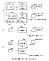
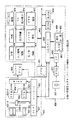
図1は、本発明映像信号記録装置、編集方法及びそのシステムの概要を説明するための説明図であり、図1Aは、カメラ一体型記録装置の構成図、図1Bは、第1の編集システムの構成図、図1Cは、第2の編集システムの構成図である。 FIG. 1 is an explanatory diagram for explaining the outline of the video signal recording apparatus, editing method and system of the present invention, FIG. 1A is a configuration diagram of a camera-integrated recording apparatus, and FIG. 1B is a first editing system. FIG. 1C is a configuration diagram of the second editing system.
図1Aに示すカメラ一体型VTR300は、カメラ部100と、第1の記録部150と、信号処理部200と、第2の記録部250と、付加的なデータを付加するための情報付加部140と、上記各部を制御する制御部120とからなる。第1の記録部150は、カメラ部100からの映像及び音声信号をそのままテープ状記録媒体160に記録するものである。また、第2の記録部250は、カメラ部100からの映像及び音声信号が、信号処理部200で圧縮されたものを、非テープ状記録媒体260に記録するものである。ここで、非テープ状記録媒体260は、テープ状記録媒体よりもアクセス速度を大幅に向上させることのできるものであり、例えばディスク状記録媒体である。
A camera-integrated VTR 300 shown in FIG. 1A includes a
図1Bに示す第1の編集システム400は、いわゆるオフライン用の編集システムであり、編集機350からなる。この編集機350は、図1Aに示したカメラ一体型VTR300で映像及び音声信号の収録された非テープ状記録媒体260を再生し、その再生映像及び音声をモニタしながら、図示しない操作部の操作により、イン点及びアウト点を指定し、編集リストを作成するものである。作成された編集リストデータは、非テープ状記録媒体380に記録される。
A first editing system 400 shown in FIG. 1B is a so-called offline editing system, and includes an
図1Cに示す第2の編集システム550は、いわゆるオンライン編集用の編集システムであり、編集機450及びこの編集機450によって制御される再生装置500からなる。この第2の編集システム550は、非テープ状記録媒体380に記録されている、第1の編集システムで作成された編集の内容に基いて、再生装置500を制御して、図1Aに示したカメラ一体型VTR300で映像及び音声信号の収録されたテープ状記録媒体160を再生するものである。ここでは、破線の矢印で示す「送出」の場合を想定しているので、再生装置500が用いられている場合について示しているが、記録媒体600に、ダビングする場合には、再生装置500は、記録装置となる。
A second editing system 550 shown in FIG. 1C is a so-called editing system for online editing, and includes an
つまり、本発明では、図1に示すように、カメラ一体型VTR300で収録を行う際に、カメラ部100からの映像及び音声信号を、第1の記録部150により、圧縮することなくそのままテープ状記録媒体160に記録すると共に、カメラ部100からの映像及び音声信号を、信号処理部200により圧縮し、第2の記録部250により非テープ状記録媒体260に記録する。そして、オフライン編集の際は、第1の編集システム400により、非テープ状記録媒体380に記録されている圧縮映像及び音声信号をモニタしながらイン点やアウト点等の編集ポイントを決定して編集リストデータを生成し、この編集リストデータを、非テープ状記録媒体380に記録する。そして、オンライン編集の際は、テープ状記録媒体160を再生装置500にセットし、非テープ状記録媒体380を、編集機450にセットし、非テープ状記録媒体380に記録されている編集リストデータに基いて、第2の編集システム550により、再生装置500を制御し、編集リストデータに基いた素材を出力するようにしている。
That is, in the present invention, as shown in FIG. 1, when recording is performed with the camera-integrated VTR 300, the video and audio signals from the
また、本発明においては、更に、カメラ一体型VTR300で、付加情報をも記録できるようにする。この付加情報としては、例えば撮影者の情報、位置情報等である。これらの情報は、第1の記録部150により、テープ状記録媒体160に記録すると共に、第2の記録部250により、非テープ状記録媒体260に記録するようにする。そして、第1の編集システム400において、オフライン編集を行う際や、第2の編集システム550において、オンライン編集を行う場合に、上記付加情報を表示し、編集ポイントを、より見つけ易くするためのインデックスとして用いるようにする。
In the present invention, additional information can also be recorded by the camera-integrated VTR 300. As this additional information, for example, photographer information, position information, and the like are included. These pieces of information are recorded on the tape-shaped
〔概要説明から導き出される効果〕
よって、圧縮された映像及び音声信号の記録されている非テープ状記録媒体260を用いてオフライン編集を行え、その際に生成した編集リストデータに基いて、テープ状記録媒体160に収録されている素材を再生することができるので、編集効率を大幅に向上させることができるといった効果、並びに、より効果のある編集、例えば撮影者の意図した編集を行うことができるという効果がある。以下、より具体的な例を、実施の形態として説明する。
[Effects derived from the explanation]
Therefore, offline editing can be performed using the
[実施の形態] [Embodiment]
B.カメラ一体型VTRの構成及びその動作説明(図2) B. Configuration of camera-integrated VTR and explanation of its operation (FIG. 2)
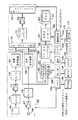
図2は、カメラ一体型VTRの構成例を示す構成図であり、このカメラ一体型VTRは、図1Aに示したカメラ一体型VTR300に対応するものである。 FIG. 2 is a configuration diagram showing a configuration example of a camera-integrated VTR, and this camera-integrated VTR corresponds to the camera-integrated VTR 300 shown in FIG. 1A.
〔接続及び構成〕
この図2に示すカメラ一体型VTRは、カメラ部100と、第1の記録部150と、信号処理部200と、第2の記録部250と、上記カメラ部100、第1の記録部150、信号処理部200及び第2の記録部250を制御するシステムコントローラ120と、操作パネル110と、タイムコード発生回路149と、血圧計148と、GPS(GrobalPositioningSystem:衛星測位方式)147とで構成される。
[Connection and configuration]
The camera-integrated VTR shown in FIG. 2 includes a
ここで、上記血圧計148は、例えばカメラ一体型VTRの使用者の親指や手首に装着されるものであり、この血圧計148によって得られる血圧データや脈拍データは、第2の記録部250によって、後述するICカード252に記録され、後に説明するオフライン編集時に、編集ポイントの探索等のインデックス情報として用いられる。また、上記GPS147は、例えばカメラ一体型VTRに登載、若しくは使用者が携帯するものであり、このGPS148によって得られる位置データは、第2の記録部250によって、後述するICカード252に記録され、後に説明するオフライン編集時に、編集ポイントの探索等のインデックス情報として用いられる。上記血圧計148、GPS147は、図1に示した情報付加部140に対応する。
Here, the
上記カメラ部100は、光学系101と、光学系101からの光を電気信号に変換するCCD(ChargeCoupledDevice)102と、プリアンプ103と、A−Dコンバータ104と、映像信号処理回路105と、マイクロフォン106と、プリアンプ107と、A−Dコンバータ108及び音声信号処理回路109とで構成される。ここで、上記映像信号処理回路105は、同期信号の付加の他、ホワイトバランス、ニー補正、ブラックバランス、ガンマ補正、シェーディング補正等の各種補正処理を行う。尚、これらの各種補正情報は、第2の記録部250によって、後述するICカード252に記録され、後に説明するオフライン編集時に、編集ポイントの探索等のインデックス情報として用いられる。
The
上記第1の記録部150は、映像信号処理回路105からの映像信号と、音声信号処理回路109からの音声信号に対して、夫々外符号エラー訂正コード及び内符号エラー訂正コードを付加し、積符号の形式に変換するエラー訂正コード付加回路151と、このエラー訂正コード付加回路151からの出力に対し、チャンネルコーディングによりディジタル変調処理を施すチャンネルコーディング回路152と、記録増幅回路153と、カセットコンパートメント154とで構成される。ここで、上記カセットコンパートメント154は、映像・テープ・カセットの磁気テープをローディングするためのテープローディング機構や、これらの動作を行わせるための駆動系、ドラムモータ及び磁気ヘッドの登載された回転ドラムとで構成される。
The
上記信号処理部200は、映像信号処理回路105からの映像信号を圧縮する映像圧縮回路201、音声信号処理回路109からの音声信号を圧縮する音声圧縮回路202及び上述と同様のエラー訂正コードを付加するエラー訂正コード付加回路203とで構成される。ここで、上記映像圧縮回路201は、例えば動き検出処理を用いたMPEG(Motion Picture Expert Group)に準拠した動画像圧縮処理、JPEG(Joint Photographic Coding Experts Group)に準拠した静止画像圧縮処理、単純な間引きによる圧縮処理等が採用可能である。また、上記音声圧縮回路202は、例えば16ビットのディジタル音声データの場合においては、下位8ビットを切り捨てる等の単純な間引きによる圧縮処理が採用可能である。
The
また上記第2の記録手段は、ICカードコントローラ251と、ICカードスロット253と、このICカードスロット253にセットされるICカード252とで構成される。ここで、ICカードは、例えばハードディスク若しくはフラッシュメモリで構成される。例えばPCMCIAに準拠したICカードが使用可能である。
The second recording means includes an
また上記システムコントローラ120は、メモリ120aと、メモリ120aに対するデータの書き込み、メモリ120aからのデータの読み出しを行う、読み出し/書き込み手段120bと、上記カメラ部100、第1の記録部150、信号処理部200及び第2の記録部250を制御するための制御手段120c、データの入出力処理を行うための入出力手段120d、タイムコード発生回路149からのタイムコードデータ、血圧計148からの血圧や脈拍データ、GPS147からの位置データ、操作部112を介して入力されるリールIDデータ、カメラ部100のセットアップデータ(ガンマやニー補正等の補正情報)等の付加データを、映像圧縮回路201及び音声圧縮回路202によって夫々圧縮された圧縮映像信号及び圧縮音声信号に付加する情報付加手段120eとで構成される。
The
〔動作〕
この図2に示すカメラ一体型VTRにおける目的は、撮像した映像信号及び集音した音声信号の記録、並びに、付加データの記録である。以上のことを前提として動作を説明する。
[Operation]
The purpose of the camera-integrated VTR shown in FIG. 2 is to record a captured video signal and a collected audio signal, and to record additional data. The operation will be described on the assumption of the above.
カメラ一体型VTRに電源が投入されると、光学系101からCCD102に入射する光は、このCCD102において光電変換され、電気信号としてプリアンプ103に供給され、利得の調整が行われた後にA−Dコンバータ104に供給される。A−Dコンバータ104に供給された電気信号は、ここでディジタル映像データに変換される。A−Dコンバータ104からのディジタル映像データは、映像信号処理回路105に供給され、上述した各種補正処理が施された後、エラー訂正コード付加回路151及び映像圧縮回路201に夫々供給される。
When the camera-integrated VTR is turned on, light incident on the
一方、マイクロフォン106で集音された音声は、このマイクロフォン106によって電気信号に変換された後に、プリアンプ107を介して、A−Dコンバータ108に供給され、このA−Dコンバータ108において、ディジタル音声データに変換される。A−Dコンバータ108からのディジタル音声データは、音声信号処理回路109に供給され、各種音声信号処理が施された後に、エラー訂正コード付加回路151及び音声圧縮回路202に夫々供給される。
On the other hand, the sound collected by the
エラー訂正コード付加回路151に夫々供給されたディジタル映像データ及びディジタル音声データは、後述するシステムコントローラ120からのサブコードデータと共に、このエラー訂正コード付加回路151において、内符号エラー訂正コード及び外符号エラー訂正コードが付加されて、積符号形式のデータに変換された後に、チャンネルコーディング回路152に供給され、このチャンネルコーディング回路152において、ディジタル変調処理が施される。チャンネルコーディング回路152からのディジタル変調信号は、記録増幅回路153を経てカセットコンパートメント154の磁気ヘッドに供給される。
The digital video data and digital audio data supplied to the error correction
一方、映像圧縮回路201においては、映像信号処理回路105からのディジタル映像データが、圧縮される。この圧縮ディジタル映像データVdは、入出力手段120dを介して、システムコントローラ120に供給される。また、音声圧縮回路202においては、音声信号処理回路109からのディジタル音声データが、圧縮される。この圧縮ディジタル音声データAdは、入出力手段120dを介して、システムコントローラ120に供給される。システムコントローラ120に供給された圧縮ディジタル映像データ及び圧縮ディジタル音声データは、読み出し/書き込み手段120bにより、メモリ120aのデータエリアに書き込まれる。
On the other hand, in the
また、タイムコード発生回路149からのタイムコードデータ、後述するリールIDデータ、血圧系148からの血圧データ、脈拍データ及びGPS147からの位置データが、入出力手段120dを介して、システムコントローラ120に供給される。システムコントローラ120に供給されたリールIDデータ、血圧データ、脈拍データ及び位置データは、読み出し/書き込み手段120bにより、メモリ120aのサブコードエリアに書き込まれる。そして更に、上記タイムコードデータは、カセットコンパートメント154のタイムコードデータ記録用の固定ヘッド(図示せず)に供給される。
Further, time code data from the time
メモリ120aに一定量の圧縮ディジタル映像データ及び圧縮ディジタル音声データが記憶されると、制御手段120cの制御の元に、読み出し/書き込み手段120bが、メモリ120aに対する読み出し制御を開始する。メモリ120aから読み出された圧縮ディジタル映像データ、圧縮ディジタル音声データ及びサブコードデータは、夫々エラー訂正コード付加回路203に供給され、このエラー訂正コード付加回路203において、外符号エラー訂正コード及び内符号エラー訂正コードが付加されて、積符号形式のデータに変換される。この積符号形式のデータは、ICカードコントローラ251を介してICカード252に供給される。
When a certain amount of compressed digital video data and compressed digital audio data is stored in the
以上のような動作状態において、使用者により、操作部112が操作されることにより、リールIDが入力されると、情報付加手段120eの制御の元に、読み出し/書き込み回路120bが、入出力手段120dを介して供給されるリールIDデータを、メモリ120aのサブコードエリアに書き込む。このサブコードエリアに書き込まれたサブコードデータは、ICカードコントローラ251に供給されると共に、エラー訂正コード付加回路151にも供給される。続いて、使用者によって、記録キー(図示せず)が押圧されると、システムコントローラ120の制御手段120cは、カセットコンパートメント154に制御信号を供給し、キャプスタンモータ、リールモータ及びドラムモータ(図示せず)の駆動を夫々開始する。これによって、セットされているビデオ・テープ・カセットの磁気テープが走行し、回転ドラムが回転する。
In the operation state as described above, when the user operates the
これによって、記録増幅回路153からのディジタル変調信号が、磁気ヘッドに供給され、ビデオ・テープ・カセットの磁気テープ上に傾斜トラックを形成するように記録されると共に、タイムコードデータが、固定ヘッドにより、ビデオ・テープ・カセットの磁気テープ上に長手トラックを形成するように記録される。また、エラー訂正コード付加回路203からのデータが、ICカードコントローラ251を介してICカードに供給され、ICカードに記録される。
As a result, the digital modulation signal from the
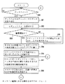
C.カメラ一体型VTRの制御動作の説明(図3) C. Explanation of control operation of camera-integrated VTR (Fig. 3)
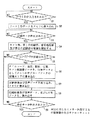
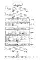
図3は、図2に示したカメラ一体型VTRの制御動作を説明するためのフローチャートであり、以下に説明する制御動作の主体は、図2に示したシステムコントローラ120の各手段である。
FIG. 3 is a flowchart for explaining the control operation of the camera-integrated VTR shown in FIG. 2, and the main body of the control operation described below is each means of the
ステップS1では、図2に示した制御手段120cが、操作部112を介して、リールIDデータが入力されたか否かを判断し、「YES」であればステップS2に移行する。
In step S1, the
ステップS2では、図2に示した読み出し/書き込み手段120bが、入出力手段120dを介して供給されるリールIDデータを、メモリ120aのサブコードデータの記憶エリアに書き込む。
In step S2, the read / write means 120b shown in FIG. 2 writes the reel ID data supplied via the input / output means 120d in the subcode data storage area of the
ステップS3では、図2に示した制御手段120cが、操作部112の記録キーが押圧されたか否かを判断し、「YES」であればステップS3に移行する。
In step S3, the
ステップS4では、図2に示した制御手段120cが、カメラ部100、第1の記録部150、信号処理部200並びに第2の記録部250に対し、夫々制御信号を供給し、上記各部の動作を開始する。
In step S4, the
ステップS5では、図2に示した制御手段120cが、タイムコードデータが供給されたか否かを判断し、「YES」であればステップS6に移行する。 In step S5, the control means 120c shown in FIG. 2 determines whether or not time code data is supplied. If “YES”, the process proceeds to step S6.
ステップS6では、図2に示した制御手段120cの制御の元に、読み出し/書き込み手段120bが、入出力手段120dを介して供給される、タイムコードデータ、血圧データ、脈拍データ、位置データ及びカメラ部調整データからなる付加データを、メモリ120aのサブコードデータの記憶エリアに書き込む。
In step S6, the time code data, blood pressure data, pulse data, position data, and camera are supplied to the read / write means 120b via the input / output means 120d under the control of the control means 120c shown in FIG. The additional data composed of the section adjustment data is written in the storage area of the subcode data in the
ステップS7では、図2に示した制御手段120cの制御の元に、読み出し/書き込み手段120bが、入出力手段120dを介して供給される、圧縮ディジタル映像データ及び圧縮ディジタル音声データを、メモリ120aのデータエリアに書き込む。
In step S7, under the control of the control means 120c shown in FIG. 2, the read / write means 120b supplies the compressed digital video data and compressed digital audio data supplied via the input / output means 120d to the
ステップS8では、図2に示した制御手段120cの制御の元に、読み出し/書き込み手段120bが、メモリ120aに記憶されている圧縮ディジタル映像データ、圧縮ディジタル音声データ並びに付加データを、読み出す。制御手段120cは、メモリ120aから読み出された圧縮ディジタル映像データ、圧縮ディジタル音声データ並びに付加データを、入出力手段120dを介して、エラー訂正コード付加回路203並びにエラー訂正コード付加回路151に夫々供給する。
In step S8, under the control of the control means 120c shown in FIG. 2, the read / write means 120b reads the compressed digital video data, compressed digital audio data, and additional data stored in the
エラー訂正コード付加回路203及び151に夫々供給された付加データは、既に説明したように、夫々サブコードデータとして、外符号エラー訂正コード及び内符号エラー訂正コードが付加される。
As described above, the outer code error correction code and the inner code error correction code are added to the additional data supplied to the error correction
ステップS9では、図2に示した制御手段120cが、操作部112の停止キーが押圧されたか否かを判断し、「YES」であれば終了し、「NO」であれば再びステップS5に移行する。
In step S9, the control means 120c shown in FIG. 2 determines whether or not the stop key of the
以上の処理が済むと、ICカード252には、圧縮ディジタル映像データ、圧縮ディジタル音声データ、サブコードデータが記録され、ビデオ・テープ・カセットの磁気テープ上には、ディジタル映像データ、ディジタル音声データ、サブコードデータが記録される。そして、素材の収録されたビデオ・テープ・カセット及びICカードは、次に説明する、オフライン用の編集システムで用いられる。
When the above processing is completed, compressed digital video data, compressed digital audio data, and subcode data are recorded on the
D.オフライン用の編集システムの構成及びその動作説明(図4) D. Configuration of offline editing system and description of its operation (Fig. 4)
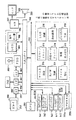
図4は、オフライン用の編集システムの構成例を示す構成図であり、このオフライン用の編集システムは、図1Bに示した第1の編集システム400に対応するものである。 FIG. 4 is a configuration diagram showing a configuration example of an offline editing system, and this offline editing system corresponds to the first editing system 400 shown in FIG. 1B.
〔接続及び構成〕
この図4に示すオフライン用の編集システムは、CPU1にバス352が接続され、このバス352に、プログラムデータDa1及びエディットリストエディタデータDa2の記憶されたROM353、RAM354、テレビジョンモニタ368への圧縮ディジタル映像データの表示用のビデオRAM355a、LCD365への画像データ化されたエディットリストの表示用のビデオRAM355b、入出力ポート356が接続され、この入出力ポート356に、インターフェース回路357を介してICカードスロット358、インターフェース回路359を介して伸長回路360、インターフェース回路361を介してフロッピー・ディスク・ドライブ362、出力回路367を介してテレビジョンモニタ368、出力回路367を介してスピーカ369が夫々接続され、更に、LCD365及び操作キー群366を有する操作パネル364が接続されて構成される。
[Connection and configuration]
The offline editing system shown in FIG. 4 has a
ここで、上記RAM354には、ROM353に記憶されているエディットリストエディタデータ、即ち、エディットリストの各データを入力するためのエディタがロードされる。そして、RAM354にロードされたエディタの記憶エリアに、順次、データが書き込まれることにより、エディットリストDa3が生成される。また、上記RAM354には、ワークエリアAr1及びバッファエリアAr2が夫々設定される。ワークエリアAr1は、CPU351のワーク用であり、バッファエリアAr2は、ICカード252から読み出された圧縮ディジタル映像データ、圧縮ディジタル音声データ及びサブコードデータや、伸長回路360で伸長処理の施された圧縮ディジタル映像データ及び圧縮ディジタル音声データのバッファリング用である。
Here, the
また、図中、一点鎖線で示す領域内に夫々示すブロックは、ROM353に記憶されているプログラムデータDa1により、電源投入後にCPU351が有する多くの機能の内、最も重要な機能を示す。
In the drawing, blocks shown in the region indicated by the alternate long and short dash line indicate the most important functions among many functions of the
キー入力認識手段370操作パネル364の操作キー群の内、どのキーが押圧されたのかを認識する機能である。
*読み出し/書き込み制御手段371ROM353からのデータの読み出し、RAM354に対するデータの書き込み、RAM354からのデータの読み出し、ビデオRAM355a及び355bに対するデータの書き込み、ビデオRAM355a及び355bからのデータの読み出しを行う機能である。
*ファイル管理手段372RAM354に保持されているエディットリストDa3を、エディットリストファイルとして、フロッピー・ディスク・ドライブ362にセットされているフロッピー・ディスク363に記録する機能と、フロッピー・ディスク363に記録されているエディットリストファイルを読み出す機能である。
*ICカードドライバ373ICカード252に対するデータの記録、並びにICカード252からのデータの読み出しを行う機能である。
*伸長ボードドライバ374伸長回路360に供給するデータや供給の形態を、伸長回路360のフォーマットに合致させるための機能である。
*情報読み取り手段375ICカード252から読み出されるデータの内、サブコードデータを抽出する機能である。
*LCD制御手段376エディットリストDa3を、画像データに変換することにより、エディットリストDa3を、LCD365の表示面上に画像として表示する機能である。
*指示認識手段377キー入力認識手段370の認識結果に基いて、使用者からの指示を認識する機能である。
*エディットリスト生成手段378キー入力認識手段370の認識結果に基いて、エディットリストDa3の対応項目のデータとして、RAM354上のエディットリストDa3に登録するための制御を、読み出し/書き込み制御手段371に対して行う機能である。
This is a function for recognizing which key is pressed in the operation key group of the key input recognition means 370
* Read / Write
* File management means 372 A function for recording the edit list Da3 held in the
* IC card driver 373 A function for recording data to the
* Decompression board driver 374 This is a function for making the data supplied to the
* Information reading means 375 A function for extracting subcode data from data read from the
* The LCD control means 376 has a function of displaying the edit list Da3 as an image on the display surface of the
*
* Based on the recognition result of the edit list generation means 378 key input recognition means 370, the control for registering in the
〔動作〕
以下、図4に示すオフライン用の編集システムの動作を説明する。但し、以下の説明では、その制御動作の主体をCPU351として説明する。既に説明した上記各手段を制御動作の主体とした説明は、項目Eにおいてフローチャートを参照して説明する。
[Operation]
The operation of the offline editing system shown in FIG. 4 will be described below. However, in the following description, the subject of the control operation will be described as the
ICカード252に記録されている圧縮ディジタル映像データ、圧縮ディジタル音声データ並びにサブコードデータが、順次、インターフェース回路357、入出力ポート356及びバス352を夫々介して供給される。CPU1は、ICカード252から読み出されるデータを、RAM354のバッファエリアAr2に書き込むと共に、書き込んだデータの内、圧縮ディジタル映像データ及び圧縮ディジタル音声データのみを、バス352、入出力ポート356及びインターフェース回路359を夫々介して、伸長回路360に供給する。そして、CPU1は、伸長回路360において伸長処理されたディジタル映像データを、ビデオRAM355aに、ディジタル音声データを、RAM354に夫々書き込み、続いて、ビデオRAM355aに書きこんだディジタル映像データを、バス352、入出力ポート356及び出力回路367を夫々介して、テレビジョンモニタ368に、RAM354に書き込んだディジタル音声データを、バス354、入出力ポート356及び出力回路367を夫々介して、スピーカ369に供給する。これによって、テレビジョンモニタ36には、ICカード252から読み出された圧縮ディジタル映像データが画像として表示され、スピーカ369からは、ICカード252から読み出された圧縮ディジタル音声データが、音声として出力される。
Compressed digital video data, compressed digital audio data, and subcode data recorded on the
一方、CPU351は、RAM354のバッファエリアAr2に保持されたデータの内、サブコードデータのみを読み出し、読み出したサブコードデータを、画像データに変換し、変換して得られた画像データを、ビデオRAM355bに書き込み、続いて、ビデオRAM355bに書き込んだ画像データを、バス352及び入出力ポート356を介して、LCD365に供給する。これによって、LCD365の表示面上には、タイムコードデータ、血圧データ、脈拍データ、位置データ、カメラ部調整データ、リールIDデータ等のサブコードデータが、画像として表示される。
On the other hand, the
以上のような状態において、使用者が、操作キー群366のイン点指定キー(図示せず)やアウト点指定キー(図示せず)を押圧すると、その押圧時点にRAM354のバッファエリアAr2に保持されているタイムコードデータ、並びにサブコードデータが、イン点若しくはアウト点のタイムコードデータ、並びにサブコードデータとして、エディットリストDa3に登録される。
In the state as described above, when the user presses an in-point specifying key (not shown) or an out-point specifying key (not shown) of the operation
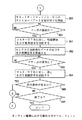
E.オフライン編集処理における動作の説明(図5〜図8) E. Explanation of operations in offline editing processing (FIGS. 5 to 8)
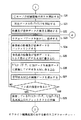
図5〜図8は、夫々図4に示したオフライン用の編集システムにおける制御動作をより詳細に説明するためのフローチャートである。以下の説明においては、制御動作の主体は、図4に示した各手段である。 5 to 8 are flowcharts for explaining the control operation in the offline editing system shown in FIG. 4 in more detail. In the following description, the main body of the control operation is each means shown in FIG.
ステップS11では、図2に示したICカードドライバ373が、ICカード252が、ICカードスロット358にセットされているか否かを判断し、「YES」であればステップS12に移行する。
In step S11, the IC card driver 373 shown in FIG. 2 determines whether or not the
ステップS12では、図2に示したファイル管理手段372が、フロッピー・ディスク363が、フロッピー・ディスク・ドライブ362にセットされているか否かを判断し、「YES」であればステップS13に移行する。
In step S12, the file management means 372 shown in FIG. 2 determines whether or not the
ステップS13では、図2に示した読み出し/書き込み制御手段371が、エディットリスト生成手段378の制御の元に、ROM353から、エディットリストエディタデータDa2を読み出す。
In step S13, the read /
ステップS14では、図2に示した読み出し/書き込み制御手段371が、読み出したエディットリストエディタデータDa2を、RAM354に書き込む。
In step S14, the read / write control means 371 shown in FIG. 2 writes the read edit list editor data Da2 into the
ステップS15では、図2に示したICカードドライバ373が、情報読み取り手段375の制御の元に、ICカード252に記録されているデータの読み取りを行う。ICカード252から読み出されたデータは、インターフェース回路357、入出力ポート356及びバス352を介して、RAM354に供給される。このとき、読み出し/書き込み制御手段371は、RAM354に対し、書き込み制御信号を供給する。これによって、ICカード252から読み出されたデータは、RAM354に書き込まれる。
In step S15, the IC card driver 373 shown in FIG. 2 reads data recorded on the
ステップS16では、図2に示した読み出し/書き込み制御手段371が、情報読み取り手段375の制御の元に、RAM354に記憶されたデータ中から、リールIDデータを読み出し、読み出したリールIDデータを、エディットリスト生成手段378に供給する。エディットリスト生成手段378は、リールIDデータを、RAM354に供給する。続いて、読み出し/書き込み制御手段371が、エディットリスト生成手段378の制御の元に、RAM354に対し、書き込み制御信号を供給する。これによって、リールIDデータは、RAM354のエディットリストDa3に登録される。
In step S16, the read /
ステップS17では、図2に示した読み出し/書き込み制御手段371が、LCD制御手段376の制御の元に、RAM354に記憶されているエディットリストデータDa3を読み出す。RAM354から読み出されたエディットリストデータDa3は、バス352を介して、LCD制御手段376に供給される。LCD制御手段376は、エディットリストデータDa3を、画像データに変換し、変換後の画像データを、ビデオRAM355bに供給する。このとき、読み出し/書き込み制御手段371は、LCD制御手段376の制御の元に、ビデオRAM355bに対し、書き込み制御信号を供給する。これによって、LCD制御手段376からのエディットリストデータDa3の画像データは、ビデオRAM355bに書き込まれる。
In step S17, the read /
ステップS18では、図2に示した読み出し/書き込み制御手段371が、LCD制御手段376の制御の元に、ビデオRAM355bに対し、読み出し制御信号を供給する。これによって、ビデオRAM355bに記憶されているエディットリストデータDa3の画像データは、バス352及び入出力ポート356を介して、LCD365に供給され、このLCD365の表示面上に、エディットリストの画像として表示される。
In step S18, the read /
ステップS19では、図2に示したキー入力認識手段370が、キー入力の認識結果を、指示認識手段377に供給する。指示認識手段377は、キー入力認識手段370からの認識結果に基いて、再生開始が指示されたか否かを判断し、「YES」であれば図6に示すフローチャートのステップS20に移行する。
In step S 19, the key
ステップS20では、図2に示した指示認識手段377の指令により、ICカードドライバ373が、バス352、入出力ポート356及びインターフェース回路357を介してICカード252に対し、読み出しを示す制御信号を供給する。これによって、ICカード252から、記録データが読み出される。読み出された記録データは、インターフェース回路357、入出力ポート356及びバス352を介して、RAM354に供給される。
In step S20, the IC card driver 373 supplies a control signal indicating reading to the
ステップS21では、図2に示した読み出し/書き込み制御手段371が、ICカードドライバ373の制御の元に、RAM354に対し、書き込み制御信号を供給する。これによって、ICカード252から読み出されたデータは、RAM354のバッファエリアAr2に記憶される。
In step S 21, the read /
ステップS22では、図2に示した読み出し/書き込み制御手段371が、情報読み取り手段375の制御の元に、RAM354に記憶されているサブコードデータを読み出し、読み出したサブコードデータを、RAM354のワークエリアAr1に書き込む。
In step S22, the read /
ステップS23では、図2に示した伸長ボードドライバ374の制御の元に、読み出し/書き込み制御手段371が、RAM354のバッファエリアAr2から、バッファリングされている圧縮ディジタル映像データ及び圧縮ディジタル音声データを読み出す。RAM354から読み出された圧縮ディジタル映像データ及び圧縮ディジタル音声データは、バス352、入出力ポート356及びインターフェース回路359を介して、伸長回路360に供給され、この伸長回路360により、元のディジタル映像データ及びディジタル音声データに復元される。伸長回路36で復元されたディジタル映像データ及びディジタル音声データは、インターフェース回路359、入出力ポート356及びバス352を介して、RAM354に供給される。
In step S23, the read /
ステップS24では、図2に示した読み出し/書き込み制御手段371が、伸長ボードドライバ374の制御の元に、RAM354に対し、書き込み制御信号を供給する。これによって、復元されたディジタル映像及び音声データは、RAM354のバッファエリアAr2に記憶される。
In
ステップS25では、図2に示した読み出し/書き込み制御手段371が、RAM354のバッファエリアAr2に記憶されているディジタル映像データを、ビデオRAM355aに書き込む。
In step S25, the read / write control means 371 shown in FIG. 2 writes the digital video data stored in the buffer area Ar2 of the
ステップS26では、図2に示した読み出し/書き込み制御手段371が、LCD制御手段376の制御の元に、RAM354のワークエリアAr1に記憶されているサブコードデータ中のタイムコードデータ及び付加データを、夫々読み出す。RAM354から読み出されたタイムコードデータ及び付加データは、LCD制御手段376に供給される。LCD制御手段376は、タイムコードデータ及び付加データを、画像データに変換し、当該画像データを、ビデオRAM355bに供給する。このとき、読み出し/書き込み制御手段371は、LCD制御手段376の制御の元に、ビデオRAM355bに対し、書き込み制御信号を供給する。これによって、上記画像データは、ビデオRAM355bに記憶される。
In step S26, the read /
ステップS27では、図2に示した読み出し/書き込み制御手段371が、ビデオRAM355aに記憶されているディジタル映像データを読み出すと共に、RAM354のバッファエリアAr2に記憶されているディジタル音声データを読み出す。ディジタル映像データ及びディジタル音声データは、バス352及び入出力ポート356を介して、出力回路367に供給される。そして、ディジタル映像データは、出力回路367により、テレビジョンモニタ368に供給され、テレビジョンモニタ368において画像として表示される。また、ディジタル音声データは、出力回路367により、スピーカ369に供給され、スピーカ369から、音声として出力される。一方、図2に示した読み出し/書き込み制御手段371が、ビデオRAM355bに記憶されている画像データを読み出す。ビデオRAM355bから読み出された画像データは、バス352及び入出力ポート356を介して、LCD365に供給され、タイムコード及び付加データの画像として表示される。
In step S27, the read / write control means 371 shown in FIG. 2 reads the digital video data stored in the
ステップS28では、図2に示したキー入力認識手段370からの認識結果に基いて、指示認識手段377が、イン点が指定されたか否かを判断し、「YES」であればステップS29に移行し、「NO」であれば再びステップS24に移行する。
In step S28, based on the recognition result from the key
ステップS29では、図2に示した読み出し/書き込み制御手段371が、エディットリスト生成手段378の制御の元に、RAM354のワークエリアAr2に記憶されているタイムコードデータ及び付加データを、RAM354に記憶されているエディットリストDa3の対応エリアに書き込む。
In step S29, the read /
図7に示すフローチャートのステップS30では、読み出し/書き込み制御手段371が、LCD制御手段376の制御の元に、RAM354のエディットリストDa3に登録されているタイムコードデータ及び付加データを、読み出す。読み出されたタイムコードデータ及び付加データは、LCD制御手段376に供給される。LCD制御手段376は、タイムコードデータ及び付加データを、画像データに変換し、当該画像データを、ビデオRAM355bに供給する。このとき、読み出し/書き込み制御手段371は、LCD制御手段376の制御の元に、RAM354に対し、書き込み制御信号を供給する。この書き込み制御信号は、RAM354に記憶されているエディットリストの画像データの、各項目の画像データの対応する記憶エリアを示すアドレスを含む。
In step S30 of the flowchart shown in FIG. 7, the read /
ステップS31では、図2に示した読み出し/書き込み制御手段371が、LCD制御手段376の制御の元に、ビデオRAM355bに対し、読み出し制御信号を供給する。これによって、ビデオRAM355bから読み出された画像データは、バス352及び入出力ポート356を介して、LCD365に供給され、このLCD365の表示面上に画像として表示される。このとき、使用者が指定したイン点のタイムコード並びに付加データが、表示されているエディットリスト内に、画像として表示される。
In step S31, the read /
ステップS32では、図2に示した伸長ボードドライバ374の制御の元に、読み出し/書き込み制御手段371が、RAM354のバッファエリアAr2から、バッファリングされている圧縮ディジタル映像データ及び圧縮ディジタル音声データを読み出す。RAM354から読み出された圧縮ディジタル映像データ及び圧縮ディジタル音声データは、バス352、入出力ポート356及びインターフェース回路359を介して、伸長回路360に供給され、この伸長回路360により、元のディジタル映像データ及びディジタル音声データに復元される。伸長回路36で復元されたディジタル映像データ及びディジタル音声データは、インターフェース回路359、入出力ポート356及びバス352を介して、RAM354に供給される。
In step S32, the read / write control means 371 reads the buffered compressed digital video data and compressed digital audio data from the buffer area Ar2 of the
ステップS33では、図2に示した読み出し/書き込み制御手段371が、伸長ボードドライバ374の制御の元に、RAM354に対し、書き込み制御信号を供給する。これによって、復元されたディジタル映像及び音声データは、RAM354のバッファエリアAr2に記憶される。
In
ステップS34では、図2に示した読み出し/書き込み制御手段371が、RAM354のバッファエリアAr2に記憶されているディジタル映像データを、ビデオRAM355aに書き込む。
In step S34, the read / write control means 371 shown in FIG. 2 writes the digital video data stored in the buffer area Ar2 of the
ステップS35では、図2に示した読み出し/書き込み制御手段371が、LCD制御手段376の制御の元に、RAM354のワークエリアAr1に記憶されているサブコードデータ中のタイムコードデータ及び付加データを、夫々読み出す。RAM354から読み出されたタイムコードデータ及び付加データは、LCD制御手段376に供給される。LCD制御手段376は、タイムコードデータ及び付加データを、画像データに変換し、当該画像データを、ビデオRAM355bに供給する。このとき、読み出し/書き込み制御手段371は、LCD制御手段376の制御の元に、ビデオRAM355bに対し、書き込み制御信号を供給する。これによって、上記画像データは、ビデオRAM355bに記憶される。
In step S35, the read / write control means 371 shown in FIG. 2 controls the time code data and additional data in the subcode data stored in the work area Ar1 of the
ステップS36では、図2に示した読み出し/書き込み制御手段371が、ビデオRAM355aに記憶されているディジタル映像データを読み出すと共に、RAM354のバッファエリアAr2に記憶されているディジタル音声データを読み出す。ディジタル映像データ及びディジタル音声データは、バス352及び入出力ポート356を介して、出力回路367に供給される。そして、ディジタル映像データは、出力回路367により、テレビジョンモニタ368に供給され、テレビジョンモニタ368において画像として表示される。また、ディジタル音声データは、出力回路367により、スピーカ369に供給され、スピーカ369から、音声として出力される。一方、図2に示した読み出し/書き込み制御手段371が、ビデオRAM355bに記憶されている画像データを読み出す。ビデオRAM355bから読み出された画像データは、バス352及び入出力ポート356を介して、LCD365に供給され、タイムコード及び付加データの画像として表示される。
In step S36, the read / write control means 371 shown in FIG. 2 reads the digital video data stored in the
ステップS37では、図2に示したキー入力認識手段370からの認識結果に基いて、指示認識手段377が、アウト点が指定されたか否かを判断し、「YES」であればステップS38に移行し、「NO」であれば再びステップS32に移行する。
In step S37, based on the recognition result from the key
ステップS38では、図2に示した読み出し/書き込み制御手段371が、エディットリスト生成手段378の制御の元に、RAM354のワークエリアAr2に記憶されているタイムコードデータ及び付加データを、RAM354に記憶されているエディットリストDa3の対応エリアに書き込む。
In step S38, the read /
ステップS39では、読み出し/書き込み制御手段371が、LCD制御手段376の制御の元に、RAM354のエディットリストDa3に登録されているタイムコードデータ及び付加データを、読み出す。読み出されたタイムコードデータ及び付加データは、LCD制御手段376に供給される。LCD制御手段376は、タイムコードデータ及び付加データを、画像データに変換し、当該画像データを、ビデオRAM355bに供給する。このとき、読み出し/書き込み制御手段371は、LCD制御手段376の制御の元に、RAM354に対し、書き込み制御信号を供給する。この書き込み制御信号は、RAM354に記憶されているエディットリストの画像データの、各項目の画像データの対応する記憶エリアを示すアドレスを含む。
In step S39, the read /
ステップS40では、図2に示した読み出し/書き込み制御手段371が、LCD制御手段376の制御の元に、ビデオRAM355bに対し、読み出し制御信号を供給する。これによって、ビデオRAM355bから読み出された画像データは、バス352及び入出力ポート356を介して、LCD365に供給され、このLCD365の表示面上に画像として表示される。このとき、使用者が指定したイン点のタイムコード並びに付加データが、表示されているエディットリスト内に、画像として表示される。
In step S40, the read / write control means 371 shown in FIG. 2 supplies a read control signal to the
ステップS41では、図2に示したキー入力認識手段370からの認識結果に基いて、指示認識手段377が、処理の終了が指示されたか否かを判断し、「YES」であればステップS42に移行し、「NO」であれば再び図6に示したフローチャートのステップS23に移行する。
In step S41, based on the recognition result from the key input recognizing means 370 shown in FIG. 2, the
ステップS42では、図2に示した読み出し/書き込み制御手段371が、ファイル管理手段372の制御の元に、RAM354に記憶されているエディットリストデータDa3を読み出す。RAM354から読み出されたエディットリストデータDa3は、バス352を介して、ファイル管理手段372に供給される。ファイル管理手段372は、エディットリストデータDa3のファイル名データを生成し、このファイル名データとエディットリストデータDa3を、バス352、入出力ポート356及びインターフェース回路361を介して、フロッピー・ディスク・ドライブ362に供給する。フロッピー・ディスク・ドライブ362は、ファイル名データを、フロッピー・ディスク363のインデックス用の領域に記録すると共に、エディットリストデータDa3を、フロッピー・ディスク363のデータの記録用のエリアに記録する。
In step S42, the read /
以上の処理により、リールIDデータ、イン点及びアウト点のタイムコードデータからなるエディットリストデータDa3が、フロッピー・ディスク363に、1つのファイルとして記録される。このエディットリストデータDa3が記録されたフロッピー・ディスク363は、カメラ一体型VTRで用いられたビデオ・テープ・カセットと共に、次に説明するオンライン用の編集システムで使用される。
Through the above processing, edit list data Da3 consisting of reel ID data and time code data of in and out points is recorded on the
F.オンライン用の編集システムの構成及びその動作説明(図9) F. Configuration and operation of online editing system (Fig. 9)
図9は、オンライン用の編集システムの構成例を示す構成図であり、このオンライン用の編集システムは、図1Cに示した第2の編集システム550に対応するものである。 FIG. 9 is a block diagram showing an example of the configuration of an online editing system. This online editing system corresponds to the second editing system 550 shown in FIG. 1C.
〔接続及び構成〕
この図9に示すオンライン用の編集システムは、図2に示したカメラ一体型VTRで素材を収録したビデオ・テープ・カセットを、エディットリストに基いて再生するための再生装置500と、この再生装置500で再生された映像及び音声データを例えば送出用のビデオ・テープ・カセットに記録するためのマスターVTR505と、上記再生装置500及びマスターVTR505を夫々制御する編集機450とで構成される。ここで、上記再生装置500は、カセット・オート・チェンジャーで構成される。
[Connection and configuration]
The online editing system shown in FIG. 9 includes a
上記再生装置500は、カメラ一体型VTRで素材を収録したビデオ・テープ・カセット501−1〜501−n等を保持するための棚装置501と、この棚装置501に保持されているビデオ・テープ・カセット501−1〜501−nの取り出し、取りだしたビデオ・テープ・カセット501−1〜501−nのVTR503−1〜503−nへのセット、VTR503−1〜503−nから排出されたビデオ・テープ・カセット501−1〜501−nの棚装置501へのセットを、コントローラ506からの制御信号に基いて行う搬送装置502、VTR503−1〜503−nと、VTR503−1〜503−nからの再生映像及び音声信号を、コントローラ506からの制御信号により選択的に出力するセレクタ504と、上記搬送装置502、VTR503−1〜503−n及びセレクタ504を夫々制御するコントローラ506とで構成される。ここで、上記コントローラ506は、内部にメモリ507を有する。このメモリ507は、棚装置502の各棚の棚番号データと、リールIDデータとからなるテーブルである。
The
このテーブルは、例えば次のような処理によって生成される。コントローラ506は、棚装置502にビデオ・テープ・カセット501−1〜501−nがセットされたときに、搬送装置502を制御して、搬送装置502に、棚装置502にセットされているビデオ・テープ・カセット501−1〜501−nを取り出させ、取りださせたビデオ・テープ・カセット501−1〜501−nを、VTR503−1〜503−nにセットさせる。次に、コントローラ506は、VTR503−1〜503−nを制御して、VTR503−〜503−nを再生状態にし、その再生映像及び音声信号中のリールIDデータを読み取る。そして、読み取ったリールIDデータと、棚装置501の棚の棚番号データとを対応させて、メモリ507に記憶する。
This table is generated by the following processing, for example. When the video tape cassettes 501-1 to 501-n are set in the
次に、上記編集機450の内部構成例について説明する。編集機450は、CPU451にバス452が接続され、このバス452に、編集のためのプログラムデータの記憶されたROM453、ワーク用のRAM454、入出力ポート455が接続され、更に、この入出力ポート455にインターフェース回路456を介してフロッピー・ディスク・ドライブ457が接続され、LCD459及び操作キー群460を有する操作パネル458が接続されて構成される。
Next, an internal configuration example of the
また、図中、破線内に示す各ブロックは、上記CPU451が有する機能である。
*入力情報判別手段470操作キー群470の押圧による指示内容の判別を行う機能である。
*読み出し/書き込み制御手段471ROM453に対する読み出し制御信号の供給、RAM454に対する読み出し、書き込み制御信号の供給を行う機能である。
*表示制御手段472テキストデータ等を画像データに変換して、LCD459に表示する機能である。
*ファイル管理手段473フロッピー・ディスク363に対するファイルデータの記録、フロッピー・ディスク363に記録されているファイルデータの読み出しを行う機能である。
*タイムコード読み取り手段474再生装置500からのタイムコードデータを読み取る機能である。
*VTR制御手段475再生装置500の各VTR503−1〜503−nに対し、再生、停止、巻き戻し、早送り等の制御、編集対象のビデオ・テープ・カセットをVTR503−1〜503−nにセットさせるためにリールIDデータの転送、マスターVTR505に対し、再生、停止、巻き戻し、早送り等の制御を行う機能である。
*計算手段476エディットリストに登録されているイン点やアウト点のタイムコードデータと、再生装置500から供給されるタイムコードデータとの差を求める機能である。
*判断手段477特定の指示内容の判別、計算手段466の求めた差に基づく編集ポイントか否かの判別、フロッピー・ディスク363の装填の判別、次の編集素材が有るか否かの判別を行う機能である。
*エディットリスト編集手段478操作キー群460の操作内容に基づいて、RAM454に記憶されているエディットリストデータDa3の対応データの内容を変更するための制御を行う機能である。
In the figure, each block shown within a broken line is a function of the
* Input information discrimination means 470 This function discriminates the content of an instruction by pressing the operation key group 470.
* Read / write control means 471 A function for supplying a read control signal to the
* Display control means 472 This function converts text data or the like into image data and displays it on the
* File management means 473 A function for recording file data on the
* Time code reading means 474 This function reads the time code data from the
* Control of playback, stop, rewind, fast forward, etc. for each VTR 503-1 to 503-n of VTR control means 475
* Calculation means 476 This is a function for obtaining the difference between the time code data of the IN point and OUT point registered in the edit list and the time code data supplied from the
* Judgment means 477 Discrimination of specific instruction contents, judgment of whether or not the editing point is based on the difference obtained by calculation means 466, judgment of loading of
* This is a function for performing control for changing the content of the corresponding data of the edit list data Da3 stored in the
〔動作〕
以下の動作説明では、説明の便宜上、上記機能ブロック470〜477を除いて行う。上記機能ブロック470〜477を制御動作の主体とした動作説明は、次の項目Gにおいて、フローチャートを参照してより詳細に説明する。
[Operation]
In the following description of the operation, the functional blocks 470 to 477 are excluded for convenience of explanation. The operation description with the functional blocks 470 to 477 as the main control operation will be described in more detail in the next item G with reference to a flowchart.
フロッピー・ディスク363がフロッピー・ディスク・ドライブ457にセットされると、CPU451の制御により、フロッピー・ディスク363から、ファイルとして記録されている、エディットリストデータDa3が読み出される。読み出されたエディットリストデータDa3は、インターフェース回路456、入出力ポート455及びバス452を介して、RAM454に記憶される。
When the
一方、再生装置500のコントローラ506は、既に説明したように、メモリ507上に、リールIDデータと、棚番号データとからなるテーブルを保持する。
On the other hand, the
CPU451は、RAM454に記憶されているエディットリストデータDa3のデータ、即ち、リールIDデータ、イン点及びアウト点のタイムコードデータを、素材単位で読み出す。そして、リールIDデータを、コントローラ506に供給する。コントローラ506は、編集機450からリールIDデータが供給されると、当該リールIDデータに対応する棚番号データを、メモリ507のテーブルから検索する。そして、その棚番号データに基いて、搬送装置502を制御することにより、当該棚番号データの示す棚装置501の棚にセットされているビデオ・テープ・カセット501−1〜501−nを取り出し、次に、VTR503−1〜503−nに装填する。そして、コントローラ506は、セレクタ504に選択制御信号を供給することにより、上記ビデオ・テープ・カセット501−1〜501−nの装填されたVTR503−1〜503−nの出力が、セレクタ504において選択されるようにする。続いて、コントローラ506は、ビデオ・テープ・カセット501−1〜501−nの装填されたVTR503−1〜503−nを一定時間(数秒)再生状態にする。
The
VTR503−1〜503−nが再生状態になると、VTR503−1〜503−nからの再生映像及び音声データが、セレクタ504及びコントローラ506を介して、編集機450に供給される。編集機450は、上記再生データ中のタイムコードデータを抽出し、当該タイムコードデータと、現在処理対象となっている素材のイン点のタイムコードデータとの差を得る。そしてその差に基いて、コントローラ506に対し、巻き戻し若しくは早送りを示す制御信号を供給する。この制御信号がコントローラ506に供給されると、コントローラ506は、VTR503−1〜503−nを、早送り若しくは巻き戻し状態にする。この間、編集機450には、上述と同様に再生データが供給される。編集機450は、抽出したタイムコードデータが、イン点のタイムコードデータからプリロール期間分だけ手前のタイムコードデータとなったときに、コントローラ506に対し、停止を示す制御信号を供給する。これによって、コントローラ506は、VTR503−1から503−nを、停止状態にする。
When the VTRs 503-1 to 503-n are in the playback state, the playback video and audio data from the VTRs 503-1 to 503-n are supplied to the
続いて、編集機450は、コントローラ506に対し、再生を示す制御信号を供給する。これによって、コントローラ506は、VTR503−1〜503−nを、再生状態にする。同時に、編集機505は、マスターVTR505を記録一時停止状態にする。
Subsequently, the
編集機450は、コントローラ506からの再生データ中から抽出したタイムコードデータと、イン点のタイムコードデータとが一致したときに、マスターVTR505を制御して、マスターVTR505の記録一時停止状態を解除する。これによって、再生装置500からの再生映像及び音声データが、マスターVTR505にセットされているビデオ・テープ・カセットの磁気テープ上に記録される。
When the time code data extracted from the reproduction data from the
編集機450は、引き続き、コントローラ506からの再生データ中から抽出したタイムコードデータと、アウト点のタイムコードデータとが一致するか否かを判断し、これらが一致したときに、マスターVTR505を制御して、マスターVTR505を記録一時停止状態にすると共に、コントローラ506に対し、停止を示す制御信号を供給する。これによって、コントローラ506は、VTR305−1〜503−nの再生を停止する。
The
そして、編集機450のCPU451は、エディットリストから、次の素材に対応するデータを読み出し、上述と同様の処理を行う。以上の処理が、エディットリストデータDa3に登録されている素材全てに対して行われることにより、マスターVTR505にセットされているビデオ・テープ・カセットには、カメラ一体型VTRで収録された映像及び音声データの内、オフライン用の編集システムで指定された必要な素材のみが全て記録される。
Then, the
尚、エディットリストデータDa3に基いて、再生を行い、その再生映像及び音声データをモニタし、その結果に基づき、オペレータが、RAM454上のエディットリストデータDa3の内容を、操作キー群460の操作により、変更し、変更後のエディットリストデータDa3に基いて、再生を行い、その再生データを、マスターVTR505にセットされているビデオ・テープ・カセットに、記録することも可能である。
The reproduction is performed based on the edit list data Da3, and the reproduced video and audio data are monitored. Based on the result, the operator can edit the contents of the edit list data Da3 on the
G.オンライン編集処理における動作の説明(図10及び図11) G. Explanation of operation in online editing process (FIGS. 10 and 11)
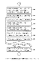
図10及び図11は、図9に示したオンライン用の編集システムにおける制御動作を説明するためのフローチャートである。以下、エディットリストデータDa3の内容を変更しないで、そのまま用いる場合を主体として説明する。 10 and 11 are flowcharts for explaining the control operation in the online editing system shown in FIG. Hereinafter, the case where the edit list data Da3 is used as it is without changing the contents will be described.
ステップS50では、図9に示した判断手段477が、フロッピー・ディスク・ドライブ457に、フロッピー・ディスク363がセットされたか否かを判断し、「YES」であればステップS51に移行する。
In step S50, the determination means 477 shown in FIG. 9 determines whether or not the
ステップS51では、図9に示したファイル管理手段473が、フロッピー・ディスク・ドライブ457に対し、エディットリストデータDa3を読み出すよう指示する。これによって、フロッピー・ディスク・ドライブ457は、フロッピー・ディスク363から、エディットリストデータDa3を読み出す。フロッピー・ディスク363から読み出されたエディットリストデータDa3は、フロッピー・ディスク・ドライブ457、インターフェース回路456、入出力ポート455及びバス452を介して、RAM454に供給され、このときに、読み出し/書き込み制御手段471からRAM461に対して与えられる書き込み制御信号により、RAM454に書き込まれる。
In step S51, the
ステップS52では、図2に示した読み出し/書き込み制御手段471が、表示制御手段472の制御の元に、RAM454に対し、読み出し制御信号を供給し、RAM454に記憶されているエディットリストデータDa3を読み出す。RAM454から読み出されたエディットリストデータDa3は、バス452を介して表示制御手段472に供給される。表示制御手段472は、RAM454からのエディットリストデータDa3を、画像データに変換し、当該画像データを、バス452及び入出力ポート455を介してLCD459に供給する。これによって、LCD459の表示面上に、エディットリストデータが、画像として表示される。
In step S52, the read / write control means 471 shown in FIG. 2 supplies a read control signal to the
ステップS53では、図2に示した入力情報判別手段470が、操作キー群460の操作内容を判別し、その判別結果を、判断手段477に供給する。判断手段477は、上記判別結果に基いて、編集開始が指示されたか否かを判断し、「YES」であればステップS54に移行し、「NO」であればステップS55に移行する。
In step S <b> 53, the input information determination unit 470 shown in FIG. 2 determines the operation content of the operation
ステップS54では、図2に示した読み出し/書き込み制御手段471が、VTR制御手段474の制御の元に、RAM454に記憶されているエディットリストデータDa3の内、処理対象の素材に対応するデータ、即ち、リールIDデータ、イン点及びアウト点のタイムコードデータを読み出し、読み出したこれらのデータを、RAM454のワークエリアに書き込む。
In step S54, the read /
ステップS55では、図2に示した入力情報判別手段470が、操作キー群460の押圧による対応データを発生し、当該データを、RAM454に供給する。このとき、読み出し/書き込み制御手段471は、エディットリスト編集手段478の制御の元に、RAM454に対し、書き込み制御信号を供給する。これによって、エディットリストデータDa3の対応部分のデータが、新たに入力されたデータによって上書きされる。尚、エディットリストデータDa3の編集を行うのにあたり、オペレータが、操作キー群460の内の再生キーを押圧することにより、既に、修正部分の確認を行っているものとする。
In step S55, the input information determination unit 470 shown in FIG. 2 generates corresponding data by pressing the operation
ステップS56では、図2に示した読み出し/書き込み制御手段471が、VTR制御手段475の制御の元に、RAM454のワークエリアに記憶されているエディットリストデータDa3の内の処理対象の素材の対応データの内の、リールIDデータを読み出す。RAM454のワークエリアから読み出されたリールIDデータは、バス452及び入出力ポート455を介して、コントローラ506に供給される。
In step S56, the read /
コントローラ506は、既に説明したように、リールIDデータと棚番号データからなるテーブルを、メモリ507に保持している。従って、編集機450からのリールIDデータと同じリールIDデータと対とされてメモリ507に記憶されている、棚番号データを認識することができる。コントローラ506は、棚番号データを認識すると、その認識に基いて、搬送装置502に対し、当該棚番号データに対応する棚からビデオ・テープ・レコーダを取り出し、VTR503−1〜503−nに装填することを示す制御信号を供給する。これによって、搬送装置502は、棚装置501の棚に夫々収納されているビデオ・テープ・カセット501−1〜501−nの内、当該棚番号データに一致する棚装置502の棚にセットされているビデオ・テープ・カセット501−1〜501−nを取り出し、取りだしたビデオ・テープ・カセット501−1〜501−nを、VTR503−1〜503−nに装填する。
As already described, the
ステップS507では、図2に示したチェンジャーコントローラ475が、コントローラ506に対し、再生を示す制御信号を供給する。コントローラ506は、セレクタ504に選択制御信号を供給することにより、上記ビデオ・テープ・カセット501−1〜501−nの装填されたVTR503−1〜503−nの出力が、セレクタ504において選択されるようにする。続いて、コントローラ506は、ビデオ・テープ・カセット501−1〜501−nの装填されたVTR503−1〜503−nを一定時間(数秒)再生状態にする。
In step S <b> 507, the
VTR503−1〜503−nが再生状態になると、VTR503−1〜503−nからの再生映像及び音声データが、セレクタ504、コントローラ506、入出力ポート455及びバス452を介して、タイムコード読み取り手段474に供給される。タイムコード読み取り手段474は、読み取ったタイムコードデータを、計算手段476に供給する。同時に、読み出し/書き込み制御手段471が、計算手段476の制御の元に、RAM454のワークエリアに記憶されているイン点及びアウト点のタイムコードデータを読み出す。RAM454から読み出されたイン点及びアウト点のタイムコードデータは、計算手段476に供給される。計算手段476は、イン点のタイムコードデータから、タイムコード読み取り手段474からのタイムコードデータを減算し、その減算結果を、判断手段477に供給する。
When the VTRs 503-1 to 503-n are in the playback state, the playback video and audio data from the VTRs 503-1 to 503-n are time code reading means via the
判断手段477は、計算手段からの減算結果が、プラスか否かを判断し、プラスであれば早送りを示すデータを、マイナスであれば巻き戻しを示すデータを、VTR制御手段475に供給する。VTR制御手段475は、判断手段477から供給されるデータに基いて、コントローラ506に対し、早送り若しくは巻き戻しを示す制御信号を供給する。これによって、コントローラ506は、ビデオ・テープ・カセット501−1〜501−nの装填されているVTR503−1〜503−nに対し、早送り若しくは巻き戻しを示す制御信号を供給し、VTR503−1〜503−nを早送り若しくは巻き戻し動作状態にする。
The
VT503−1〜503−nからの再生データは、コントローラ506、入出力ポート455及びバス452を介して、タイムコード読み取り手段474に供給される。タイムコード読み取り手段474は、再生データ中からタイムコードデータを抽出し、抽出したタイムコードデータを、計算手段476に供給する。計算手段476は、イン点のタイムコードデータから、タイムコード読み取り手段474からのタイムコードデータを減算し、この減算結果を、判断手段477に供給する。判断手段477は、当該減算結果が、マイナスで、且つ、プリロール分の時間との差が所定時間分になったか否かを判断し、その判断結果を、VTR制御手段475に供給する。VTR制御手段475は、判断手段477からの判断結果に基いて、停止を示す制御信号を、コントローラ506に供給する。
The reproduction data from the VTs 503-1 to 503-n is supplied to the time
これによって、コントローラ506は、VTR503−1〜503−nに対し、停止を示す制御信号を供給し、VTR503−1〜503−nを停止状態にする。続いて、チェンジャーコントローラ475は、再生を示す制御信号を、コントローラ506に供給する。これによって、コントローラ506は、VTR503−1〜503−nに対し、再生を示す制御信号を供給し、VTR503−1〜503−nを、再生状態にする。VTR503−1〜503−nが再生状態になると、再生データが、コントローラ506、入出力ポート455及びバス452を介して、タイムコード読み取り手段474に供給される。
As a result, the
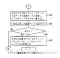
ステップS58では、図2に示したVTR制御手段475が、マスターVTR505に対し、記録一時停止状態を示す制御信号を供給する。これによって、マスターVTR505は、記録一時停止状態となる。
In step S58, the VTR control means 475 shown in FIG. 2 supplies a control signal indicating a recording pause state to the
ステップS59では、図2に示したタイムコード読み取り手段474が、コントローラ506からの再生データ中からタイムコードデータを抽出し、抽出したタイムコードデータを、計算手段475に供給する。計算手段475は、イン点のタイムコードデータから、タイムコード読み取り手段474からのタイムコードデータを減算し、その減算結果を、判断手段477に供給する。
In step S59, the time code reading means 474 shown in FIG. 2 extracts time code data from the reproduction data from the
ステップS60では、図2に示した判断手段476が、計算手段476からの減算結果が、イン点よりも1フレーム手前を示す値であるか否かを判断し、「YES」であればステップS61に移行する。
In step S60, the
ステップS61では、図2に示したVTR制御手段475が、マスターVTR505に対し、記録開始を示す制御信号を供給する。これによって、マスターVTR505は、記録を開始する。
In step S61, the VTR control means 475 shown in FIG. 2 supplies a control signal indicating the start of recording to the
ステップS62では、図2に示したVTR制御手段475が、コントローラ506に対し、セレクタ504から出力を行うことを示す制御信号を供給する。これによって、コントローラ506は、セレクタ504に対し、制御信号を供給し、VTR503−1〜503−nからの再生データを、出力させる。セレクタ504から出力された再生データは、マスターVTR505に供給され、このマスターVTR505にセットされているビデオ・テープ・カセットの磁気テープ上に傾斜トラックを形成するように記録される。
In step S <b> 62, the
ステップS63では、図2に示したタイムコード読み取り手段474が、コントローラ506からの再生データ中からタイムコードデータを抽出し、抽出したタイムコードデータを、計算手段475に供給する。計算手段475は、アウト点のタイムコードデータから、タイムコード読み取り手段474からのタイムコードデータを減算し、その減算結果を、判断手段477に供給する。判断手段476は、計算手段476からの減算結果が、アウト点を示す値であるか否かを判断し、「YES」であればステップS64に移行する。
In
ステップS64では、図2に示したVTR制御手段475が、マスターVTR505に対し、記録一時停止を示す制御信号を供給する。これによって、マスターVTR505は、記録一時停止状態となる。
In step S64, the VTR control means 475 shown in FIG. 2 supplies a control signal indicating recording pause to the
ステップS65では、図2に示した読み出し/書き込み制御手段471が、判断手段477の制御の元に、RAM454に記憶されているエディットリストデータDa3の内、現時点で処理の終了した素材に対応するデータの次のデータを読み出す。RAM454から読み出されたデータは、バス452を介して判断手段477に供給される。判断手段477は、RAM454からのデータが、エディットリストデータDa3の登録データであるか否かを判断し、「YES」であれば再び図10に示したフローチャートのステップS57に移行し、「NO」であればステップS66に移行する。尚、次の素材がない場合には、RAM454上にはデータが書き込まれていないのであるから、例えば、全て“0”若しくは“1”となっており、容易に判別がつけられる。
In step S65, the read /
ステップS66では、図2に示した入力情報判別手段470が、操作キー群460の操作内容を判別し、その判別結果を、判断手段477に供給する。判断手段477は、上記判別結果に基いて、編集処理の終了が指示されたか否かを判断し、「YES」であれば終了し、「NO」であれば再び図10に示したフローチャートのステップS50に移行する。
In step S 66, the input information determination unit 470 shown in FIG. 2 determines the operation content of the operation
以上の処理が、エディットリストデータDa3に登録されている全ての素材について行われることにより、マスターVTR505にセットされているビデオ・テープ・カセットの磁気テープ上に、所望の素材のみを記録することができる。
By performing the above processing for all the materials registered in the edit list data Da3, only desired materials can be recorded on the magnetic tape of the video tape cassette set in the
〔変形例〕
尚、編集素材の数を示す値をフラグとして保持しておき、1つの素材の処理が済む都度、“1”ずつ減算し、その減算結果が“0”になったか否かによって、次の素材が有るか否かを判断するようにしても良い。
[Modification]
Note that a value indicating the number of editing materials is held as a flag, and every time one material is processed, “1” is subtracted, and the next material is determined depending on whether or not the subtraction result is “0”. It may be determined whether or not there is.
〔変形例〕
上述の例においては、マスターVTR505を用いた場合について説明したが、勿論、そのまま送出するようにしても良い。その場合には、セレクタ504の出力端子には、マスターVTR505の代わりに、送出装置等が接続される。
[Modification]
In the above example, the case where the
〔実施の形態における効果〕
このように、本実施の形態においては、カメラ一体型VTRで収録を行うときに、ビデオ・テープ・カセットには撮像映像及び音声信号を、圧縮等せずに記録し、ICカード252には、撮像映像及び音声信号を、圧縮して記録し、しかもその際、血圧計148からの血圧データ及び脈拍データ、GPS147からの位置データをも、各信号のサブコードエリアに含ませて記録する。
[Effect in the embodiment]
As described above, in the present embodiment, when recording is performed with a camera-integrated VTR, the video image and audio signal are recorded on the video tape cassette without compression, and the
次に、オフライン用の編集システムにおいて、上記ICカード252に記録されている圧縮映像及び音声信号、上記血圧データ、脈拍データ、位置データを参照して、イン点及びアウト点を決定して素材を指定し、エディットリストデータDa3を生成し、当該エディットリストデータDa3を、フロッピー・ディスク363に記録する。
Next, in the editing system for offline use, reference is made to the compressed video and audio signals recorded on the
次に、オンライン用の編集システムにおいて、上記フロッピー・ディスク363からエディットリストデータDa3を読み出し、必要に応じてその内容を変更し、変更後のエディットリストデータDa3に基いて、カメラ一体型VTRで素材を収録したビデオ・テープ・カセット501−1〜501−nの内の必要な部分を自動的に再生し、その再生データを記録若しくは送出する。
Next, in the editing system for online use, the edit list data Da3 is read from the
従って、編集処理の最初から最後までテープ状記録媒体を使用する場合と比較して、特にイン点及びアウト点の指定を行う編集時における編集効率を大幅に向上させることができると共に、血圧データ、脈拍データ、位置データ等の付加データを参照して編集できるので、より撮影者の意図にそった編集結果を得ることができる。例えば、モニタに表示された画像を見ながら編集ポイントを決定するよりも、撮影者の血圧や脈拍が上がったところを編集ポイントとした方が、より撮影者の意図にそった編集が行える可能性がある。例えば、一瞬の間だけ、貴重な生物を撮影者が捉えた場合、その瞬間の画像をビデオ・テープ・カセットの磁気テープ上から探し出すのは、時間もかかり、また、見過ごすこともあるが、そのような場合には、血圧や脈拍が上がる可能性が高いので、血圧や脈拍が上がっている位置をサーチすれば、最も貴重な部分を短時間でサーチできることになる。 Therefore, compared with the case where the tape-like recording medium is used from the beginning to the end of the editing process, it is possible to greatly improve the editing efficiency especially during editing in which the in point and the out point are designated, and the blood pressure data, Since editing can be performed with reference to additional data such as pulse data and position data, it is possible to obtain an editing result more in line with the photographer's intention. For example, rather than deciding an edit point while looking at the image displayed on the monitor, it is possible to edit more according to the photographer's intention if the point where the photographer's blood pressure or pulse is increased is used as the edit point. There is. For example, if a photographer captures a precious creature for a moment, searching for the image of that moment on the magnetic tape of a video tape cassette is time consuming and sometimes overlooked. In such a case, since there is a high possibility that the blood pressure and the pulse will rise, if the position where the blood pressure and the pulse are raised is searched, the most valuable part can be searched in a short time.
100‥‥カメラ部、101‥‥光学系、102‥‥CCD、103、104‥‥プリアンプ、104、108‥‥A−Dコンバータ、105‥‥映像信号処理回路、106‥‥マイクロフォン、109‥‥音声信号処理回路、110‥‥操作パネル、111‥‥LCD、112‥‥操作部、120‥‥システムコントローラ、120‥‥aメモリ、120‥‥b読み出し/書き込み手段、120‥‥c制御手段、120‥‥d入出力手段、120‥‥e情報付加手段、147‥‥GPS、148‥‥血圧計、149‥‥タイムコード発生回路、150‥‥第1の記録部、151‥‥エラー訂正コード付加回路、152‥‥チャンネルコーディング回路、153‥‥記録増幅回路、154‥‥カセットコンパートメント、160‥‥テープ状記録媒体、200‥‥信号処理部、201‥‥映像圧縮回路、202‥‥音声圧縮回路、203‥‥エラー訂正コード付加回路、250‥‥第2の記録部、251‥‥ICカードコントローラ、252‥‥ICカード、253‥‥ICカードスロット、260‥‥非テープ状記録媒体、300‥‥カメラ一体型VTR、350‥‥編集機、351‥‥CPU、352‥‥バス、353‥‥ROM、Da1‥‥プログラムデータ、Da2‥‥エディットリストデータ、354‥‥RAM、Da3‥‥エディットリスト、355a、355b‥‥ビデオRAM、356‥‥入出力ポート、357、359、361‥‥インターフェース回路、358‥‥ICカードスロット、360‥‥伸長ボード、362‥‥フロッピー・ディスク・ドライブ、363‥‥フロッピー・ディスク、364‥‥操作パネル、365‥‥LCD、366‥‥操作キー群、367‥‥出力回路、368‥‥テレビジョンモニタ、370‥‥キー入力認識手段、371‥‥読み出し/書き込み制御手段、372‥‥ファイル管理手段、373‥‥ICカードドライバ、374‥‥伸長ボードドライバ、375‥‥情報読み取り手段、376‥‥LCD制御手段、377‥‥指示認識手段、378‥‥エディットリスト生成手段、400‥‥第1の編集システム、450‥‥編集機、451‥‥CPU、452‥‥バス、453‥‥ROM、454‥‥RAM、455‥‥入出力ポート、456‥‥インターフェース回路、457‥‥フロッピー・ディスク・ドライブ、458‥‥操作パネル、459‥‥LCD、460‥‥操作キー群、460‥‥入力情報判別手段、461‥‥読み出し/書き込み制御手段、462‥‥表示制御手段、463‥‥ファイル管理手段、464‥‥タイムコード読み取り手段、465‥‥VTR制御手段、466‥‥計算手段、467‥‥判断手段、500‥‥再生装置、501−1〜501−n‥‥ビデオ・テープ・カセット、501‥‥棚装置、502‥‥カセット搬送部、503−1〜503−n‥‥VTR、504‥‥セレクタ、505‥‥マスターVTR、506‥‥コントローラ、507‥‥メモリ、550‥‥第2の編集システム、600‥‥記録媒体
DESCRIPTION OF
Claims (6)
ソース映像信号を第1の記録媒体に記録すると共に、上記ソース映像信号を圧縮した圧縮映像信号を第2の記録媒体に記録するステップと、
上記第2の記録媒体に記録された圧縮映像信号を使用して、上記ソース映像信号を編集するための編集リストを生成するステップと、
上記編集リストに基づいて上記ソース映像信号を編集するステップと、
からなることを特徴とする編集方法。 In an editing method for editing a video signal,
Recording a source video signal on a first recording medium and recording a compressed video signal obtained by compressing the source video signal on a second recording medium;
Generating an edit list for editing the source video signal using the compressed video signal recorded on the second recording medium;
Editing the source video signal based on the edit list;
An editing method characterized by comprising:
ソース映像信号を第1の記録媒体に記録すると共に、上記ソース映像信号を圧縮した圧縮映像信号を第2の記録媒体に記録する手段と、
上記第2の記録媒体に記録された圧縮映像信号を使用して、上記ソース映像信号を編集するための編集リストを生成する手段と、
上記編集リストに基づいて上記ソース映像信号を編集する手段と、
からなることを特徴とする編集装置。 In an editing device for editing video signals,
Means for recording a source video signal on a first recording medium and recording a compressed video signal obtained by compressing the source video signal on a second recording medium;
Means for generating an edit list for editing the source video signal using the compressed video signal recorded on the second recording medium;
Means for editing the source video signal based on the edit list;
An editing device characterized by comprising:
ソース映像信号を圧縮した圧縮映像信号を受け取るステップと、
上記圧縮映像信号を非テープ状記録媒体に記憶するステップと、
上記圧縮映像信号を使用して上記ソース映像信号を編集するための編集リストを生成するステップと、
からなることを特徴とする編集方法。 In an editing method for editing a video signal,
Receiving a compressed video signal obtained by compressing the source video signal;
Storing the compressed video signal in a non-tape recording medium;
Generating an edit list for editing the source video signal using the compressed video signal;
An editing method characterized by comprising:
ソース映像信号を圧縮した圧縮映像信号を受け取る手段と、
上記圧縮映像信号を非テープ状記録媒体に記憶する手段と、
上記圧縮映像信号を使用して上記ソース映像信号を編集するための編集リストを生成する手段と、
からなることを特徴とする編集装置。 In an editing device for editing video signals,
Means for receiving a compressed video signal obtained by compressing the source video signal;
Means for storing the compressed video signal in a non-tape recording medium;
Means for generating an edit list for editing the source video signal using the compressed video signal;
An editing device characterized by comprising:
ソース映像信号を受け取るステップと、
上記ソース映像信号を圧縮した圧縮映像信号を使用して生成された編集リストを受け取るステップと、
上記編集リストを使用して上記ソース映像信号を編集するステップと、
上記圧縮映像信号を非テープ状記録媒体に記憶するステップと、
上記圧縮映像信号を使用して上記ソース映像信号を編集するための編集リストを生成するステップと、
からなることを特徴とする編集方法。 In an editing method for editing a video signal,
Receiving a source video signal;
Receiving an edit list generated using a compressed video signal obtained by compressing the source video signal;
Editing the source video signal using the edit list;
Storing the compressed video signal in a non-tape recording medium;
Generating an edit list for editing the source video signal using the compressed video signal;
An editing method characterized by comprising:
ソース映像信号を受け取る手段と、
上記ソース映像信号を圧縮した圧縮映像信号を使用して生成された編集リストを受け取る手段と、
上記編集リストを使用して上記ソース映像信号を編集する手段と、
上記圧縮映像信号を非テープ状記録媒体に記憶する手段と、
上記圧縮映像信号を使用して上記ソース映像信号を編集するための編集リストを生成する手段と、
からなることを特徴とする編集装置。
In an editing device for editing video signals,
Means for receiving a source video signal;
Means for receiving an edit list generated using a compressed video signal obtained by compressing the source video signal;
Means for editing the source video signal using the edit list;
Means for storing the compressed video signal in a non-tape recording medium;
Means for generating an edit list for editing the source video signal using the compressed video signal;
An editing device characterized by comprising:
Priority Applications (1)
| Application Number | Priority Date | Filing Date | Title |
|---|---|---|---|
| JP2005136516A JP4114675B2 (en) | 2005-05-09 | 2005-05-09 | Editing method and editing apparatus |
Applications Claiming Priority (1)
| Application Number | Priority Date | Filing Date | Title |
|---|---|---|---|
| JP2005136516A JP4114675B2 (en) | 2005-05-09 | 2005-05-09 | Editing method and editing apparatus |
Related Parent Applications (1)
| Application Number | Title | Priority Date | Filing Date |
|---|---|---|---|
| JP2002231522A Division JP3815398B2 (en) | 2002-08-08 | 2002-08-08 | Editing method and editing apparatus |
Publications (2)
| Publication Number | Publication Date |
|---|---|
| JP2005295584A true JP2005295584A (en) | 2005-10-20 |
| JP4114675B2 JP4114675B2 (en) | 2008-07-09 |
Family
ID=35327927
Family Applications (1)
| Application Number | Title | Priority Date | Filing Date |
|---|---|---|---|
| JP2005136516A Expired - Fee Related JP4114675B2 (en) | 2005-05-09 | 2005-05-09 | Editing method and editing apparatus |
Country Status (1)
| Country | Link |
|---|---|
| JP (1) | JP4114675B2 (en) |
-
2005
- 2005-05-09 JP JP2005136516A patent/JP4114675B2/en not_active Expired - Fee Related
Also Published As
| Publication number | Publication date |
|---|---|
| JP4114675B2 (en) | 2008-07-09 |
Similar Documents
| Publication | Publication Date | Title |
|---|---|---|
| JP3528183B2 (en) | Editing system and method, recording device, and editing device | |
| JP2001111963A (en) | Recording and playback method for video camera using optical disk | |
| JP3629764B2 (en) | Video signal recording apparatus, recording method, editing method and system thereof | |
| US20030219223A1 (en) | Recording apparatus, editor terminal apparatus, recording medium, and video content editing support system and method using them | |
| JP4218029B2 (en) | Video recording device | |
| JP3815398B2 (en) | Editing method and editing apparatus | |
| KR101025505B1 (en) | Data processing apparatus and data processing method, editing processing apparatus and editing processing method, recording medium | |
| JP4114675B2 (en) | Editing method and editing apparatus | |
| JP3780910B2 (en) | Optical disk recording device | |
| JP2840742B2 (en) | Video signal recording device | |
| JPH08147943A (en) | Editing method and system | |
| JP4772742B2 (en) | Image reproducing apparatus, image reproducing method, and program recording medium | |
| JPH09154099A (en) | Video editing equipment | |
| JP2000217055A (en) | Image processing device | |
| JPH11339446A (en) | Recording and playback device | |
| JP2000215648A (en) | Recording device | |
| JP2002237973A (en) | Recording device, recording method, and imaging device | |
| JPH11213630A (en) | Playback video / audio data identification method, video / audio data editing method, playback video / audio data identification device, and video / audio data editing device | |
| JP2983642B2 (en) | Video and audio information gathering system using video camera and its editing system | |
| US20020061182A1 (en) | Video signal recording apparatus, video signal recording/reproducing method and video signal recording method | |
| JPH07123297B2 (en) | Audio recording method for still picture disks | |
| JPH08221955A (en) | Recording / reproducing method and apparatus, editing method and apparatus | |
| JP4787206B2 (en) | Information recording apparatus and information recording method | |
| JP3728005B2 (en) | Recording / playback device | |
| JP4208022B2 (en) | Information editing apparatus, information editing method, and program recording medium |
Legal Events
| Date | Code | Title | Description |
|---|---|---|---|
| A131 | Notification of reasons for refusal |
Free format text: JAPANESE INTERMEDIATE CODE: A131 Effective date: 20060926 |
|
| A521 | Written amendment |
Free format text: JAPANESE INTERMEDIATE CODE: A523 Effective date: 20061127 |
|
| A02 | Decision of refusal |
Free format text: JAPANESE INTERMEDIATE CODE: A02 Effective date: 20070313 |
|
| A521 | Written amendment |
Free format text: JAPANESE INTERMEDIATE CODE: A523 Effective date: 20070510 |
|
| A911 | Transfer of reconsideration by examiner before appeal (zenchi) |
Free format text: JAPANESE INTERMEDIATE CODE: A911 Effective date: 20070525 |
|
| TRDD | Decision of grant or rejection written | ||
| A01 | Written decision to grant a patent or to grant a registration (utility model) |
Free format text: JAPANESE INTERMEDIATE CODE: A01 Effective date: 20080325 |
|
| A61 | First payment of annual fees (during grant procedure) |
Free format text: JAPANESE INTERMEDIATE CODE: A61 Effective date: 20080407 |
|
| FPAY | Renewal fee payment (event date is renewal date of database) |
Free format text: PAYMENT UNTIL: 20110425 Year of fee payment: 3 |
|
| FPAY | Renewal fee payment (event date is renewal date of database) |
Free format text: PAYMENT UNTIL: 20110425 Year of fee payment: 3 |
|
| LAPS | Cancellation because of no payment of annual fees |