JP2005295557A - Routing architecture - Google Patents
Routing architecture Download PDFInfo
- Publication number
- JP2005295557A JP2005295557A JP2005100424A JP2005100424A JP2005295557A JP 2005295557 A JP2005295557 A JP 2005295557A JP 2005100424 A JP2005100424 A JP 2005100424A JP 2005100424 A JP2005100424 A JP 2005100424A JP 2005295557 A JP2005295557 A JP 2005295557A
- Authority
- JP
- Japan
- Prior art keywords
- cell
- communication system
- digital communication
- routing
- node
- Prior art date
- Legal status (The legal status is an assumption and is not a legal conclusion. Google has not performed a legal analysis and makes no representation as to the accuracy of the status listed.)
- Withdrawn
Links
- 238000012545 processing Methods 0.000 claims abstract description 52
- 238000004891 communication Methods 0.000 claims abstract description 48
- 230000008878 coupling Effects 0.000 claims abstract description 5
- 238000010168 coupling process Methods 0.000 claims abstract description 5
- 238000005859 coupling reaction Methods 0.000 claims abstract description 5
- 238000012423 maintenance Methods 0.000 claims description 16
- 238000012546 transfer Methods 0.000 claims description 6
- 230000007723 transport mechanism Effects 0.000 claims description 5
- 230000006870 function Effects 0.000 description 21
- 238000013461 design Methods 0.000 description 4
- 230000007246 mechanism Effects 0.000 description 4
- 238000000034 method Methods 0.000 description 4
- 230000008901 benefit Effects 0.000 description 3
- 230000017525 heat dissipation Effects 0.000 description 3
- 230000006872 improvement Effects 0.000 description 3
- 238000012986 modification Methods 0.000 description 3
- 230000004048 modification Effects 0.000 description 3
- 230000008569 process Effects 0.000 description 3
- 230000005540 biological transmission Effects 0.000 description 2
- 230000003139 buffering effect Effects 0.000 description 2
- 238000001816 cooling Methods 0.000 description 2
- 238000010586 diagram Methods 0.000 description 2
- 239000004744 fabric Substances 0.000 description 2
- 238000007689 inspection Methods 0.000 description 2
- 230000002093 peripheral effect Effects 0.000 description 2
- 230000003213 activating effect Effects 0.000 description 1
- 238000005538 encapsulation Methods 0.000 description 1
Images

Classifications
-
- B—PERFORMING OPERATIONS; TRANSPORTING
- B66—HOISTING; LIFTING; HAULING
- B66C—CRANES; LOAD-ENGAGING ELEMENTS OR DEVICES FOR CRANES, CAPSTANS, WINCHES, OR TACKLES
- B66C13/00—Other constructional features or details
- B66C13/04—Auxiliary devices for controlling movements of suspended loads, or preventing cable slack
- B66C13/08—Auxiliary devices for controlling movements of suspended loads, or preventing cable slack for depositing loads in desired attitudes or positions
-
- H—ELECTRICITY
- H04—ELECTRIC COMMUNICATION TECHNIQUE
- H04L—TRANSMISSION OF DIGITAL INFORMATION, e.g. TELEGRAPHIC COMMUNICATION
- H04L12/00—Data switching networks
- H04L12/54—Store-and-forward switching systems
- H04L12/56—Packet switching systems
- H04L12/5601—Transfer mode dependent, e.g. ATM
-
- B—PERFORMING OPERATIONS; TRANSPORTING
- B66—HOISTING; LIFTING; HAULING
- B66C—CRANES; LOAD-ENGAGING ELEMENTS OR DEVICES FOR CRANES, CAPSTANS, WINCHES, OR TACKLES
- B66C13/00—Other constructional features or details
- B66C13/12—Arrangements of means for transmitting pneumatic, hydraulic, or electric power to movable parts of devices
-
- H—ELECTRICITY
- H04—ELECTRIC COMMUNICATION TECHNIQUE
- H04L—TRANSMISSION OF DIGITAL INFORMATION, e.g. TELEGRAPHIC COMMUNICATION
- H04L49/00—Packet switching elements
- H04L49/10—Packet switching elements characterised by the switching fabric construction
- H04L49/104—Asynchronous transfer mode [ATM] switching fabrics
- H04L49/105—ATM switching elements
- H04L49/107—ATM switching elements using shared medium
-
- H—ELECTRICITY
- H04—ELECTRIC COMMUNICATION TECHNIQUE
- H04L—TRANSMISSION OF DIGITAL INFORMATION, e.g. TELEGRAPHIC COMMUNICATION
- H04L49/00—Packet switching elements
- H04L49/15—Interconnection of switching modules
- H04L49/1553—Interconnection of ATM switching modules, e.g. ATM switching fabrics
- H04L49/1576—Crossbar or matrix
-
- H—ELECTRICITY
- H04—ELECTRIC COMMUNICATION TECHNIQUE
- H04L—TRANSMISSION OF DIGITAL INFORMATION, e.g. TELEGRAPHIC COMMUNICATION
- H04L49/00—Packet switching elements
- H04L49/25—Routing or path finding in a switch fabric
- H04L49/256—Routing or path finding in ATM switching fabrics
-
- H—ELECTRICITY
- H04—ELECTRIC COMMUNICATION TECHNIQUE
- H04L—TRANSMISSION OF DIGITAL INFORMATION, e.g. TELEGRAPHIC COMMUNICATION
- H04L12/00—Data switching networks
- H04L12/54—Store-and-forward switching systems
- H04L12/56—Packet switching systems
- H04L12/5601—Transfer mode dependent, e.g. ATM
- H04L2012/5638—Services, e.g. multimedia, GOS, QOS
- H04L2012/5665—Interaction of ATM with other protocols
Landscapes
- Engineering & Computer Science (AREA)
- Computer Networks & Wireless Communication (AREA)
- Signal Processing (AREA)
- Physics & Mathematics (AREA)
- Mathematical Physics (AREA)
- Mechanical Engineering (AREA)
- Data Exchanges In Wide-Area Networks (AREA)
Abstract
Description
本発明は、遠隔通信の分野に関し、より詳細にはデータ通信に関する。 The present invention relates to the field of telecommunications, and more particularly to data communications.
データ通信は21世紀の生活を反映している。電子メールやインターネットなどのアプリケーションは、ますます主流になっている。さらに、音声トラフィックは、回線交換型のネットワークから、ボイス・オーバIP(「VoIP」)アプリケーションをサポートするパケット交換型のネットワークに移行中である。その結果、このようなアプリケーションの受け入れや採用が増大し続けるのにしたがってデータ・トラフィックの増加が続いている。 Data communication reflects the life of the 21st century. Applications such as e-mail and the Internet are becoming more and more mainstream. In addition, voice traffic is moving from circuit-switched networks to packet-switched networks that support voice over IP ("VoIP") applications. As a result, data traffic continues to increase as acceptance and adoption of such applications continue to increase.
データ・アプリケーションの引き続く拡大により、有線および無線の正確な高速アクセスに対する消費者の需要が増加している。データ通信をサポートするシステムは、通常、いくつかのアプリケーション処理(「AP」)ノード、または通信ノードを利用する。このAPノードならびにVoIPアプリケーションは、有線および無線の高速アクセスによって駆動することができる。 With the continued expansion of data applications, consumer demand for accurate wired and wireless high-speed access is increasing. Systems that support data communication typically utilize several application processing (“AP”) nodes, or communication nodes. This AP node and VoIP application can be driven by wired and wireless high speed access.
APノードは、それら相互間での情報の伝送のために、移送構造物(transport fabric)または相互接続構造物(interconnect fabric)を介して相互接続される。高速データ通信をサポートするために、これらの相互接続構造物を、セルまたはパケット・ベースにして、いくつかの異なる高速データ通信フォーマットのうち任意の1つを使用可能にすることができる。したがって、セルまたはパケット情報のルーティングまたは転送は、ますます重要な機能となっている。 AP nodes are interconnected via a transport fabric or interconnect fabric for the transmission of information between them. In order to support high speed data communication, these interconnect structures can be cell or packet based to enable any one of several different high speed data communication formats. Accordingly, routing or forwarding of cell or packet information has become an increasingly important function.
各APノードは、典型的には回路基板によって実現される。各APノード内では、セルまたはパケット情報を、専用のスイッチによって、基板上の任意の数の処理装置にルーティングまたは転送することができる。このスイッチは、APノードの回路基板についての情報トラフィックの流れを効果的に管理する。 Each AP node is typically realized by a circuit board. Within each AP node, cell or packet information can be routed or forwarded to any number of processing devices on the board by a dedicated switch. This switch effectively manages the flow of information traffic on the circuit board of the AP node.
専用スイッチの使用は効果的であるが、注意すべき制限がある。まず、専用スイッチは、決して少なくはない量の電力を消費する。したがって、消費電力および放熱の問題に注意が必要なことがある。さらに、各専用スイッチのコスト、およびAPノードの回路基板上で各スイッチが消費するスペースもまた、システムの設計および効率に影響を与え得る。 The use of a dedicated switch is effective, but there are limitations to note. First, a dedicated switch never consumes a significant amount of power. Therefore, attention may be required to the problem of power consumption and heat dissipation. In addition, the cost of each dedicated switch and the space that each switch consumes on the circuit board of the AP node can also affect the design and efficiency of the system.
したがって、専用スイッチの制限を回避するAPノードのアーキテクチャが必要とされる。さらに、電力および冷却バジェット(budget)の改善、ならびに基板上の消費スペースおよび総コストの削減を支援するルーティング・アーキテクチャが望まれる。 Therefore, there is a need for an AP node architecture that avoids the limitations of dedicated switches. In addition, a routing architecture is desired that helps improve power and cooling budgets, as well as reduce space consumption and total cost on the board.
本発明は、電力および冷却バジェットを改善するとともに、基板上の消費スペースおよび総コストを削減するルーティング・アーキテクチャを提供する。より詳細には、本発明は、アプリケーション・プロセッサ間でセルおよび/またはパケット情報をルーティングするための通信ノード・アーキテクチャを提供する。本発明は、たとえばEthernet(登録商標、以下同)スイッチなどの専用スイッチ装置を必要としない通信ノード・アーキテクチャを実現する。この通信ノード・アーキテクチャは、たとえば無線ノード・コントローラ、基地局コントローラ(base station controller)、およびトラフィック処理コントローラを含めた数多くの用途に使用することができる。 The present invention provides a routing architecture that improves power and cooling budgets while reducing the space consumed and total cost on the board. More particularly, the present invention provides a communication node architecture for routing cell and / or packet information between application processors. The present invention implements a communication node architecture that does not require a dedicated switch device such as, for example, an Ethernet (registered trademark) switch. This communication node architecture can be used for a number of applications including, for example, a radio node controller, a base station controller, and a traffic processing controller.
ある実施形態では、本発明の通信ノード・アーキテクチャは、当技術分野で周知の専用スイッチング装置の代わりに、セルおよび/またはパケット情報をルーティングまたは転送するための少なくとも2つのネットワーク処理装置を含む。各ネットワーク処理装置は、たとえば周辺コンポーネント相互接続(「PCI」)バスなどの共有バス構造を介して相互接続することができる。この共有バス構造により、ネットワーク処理装置を、各ネットワーク処理装置によって実行される動作(duty)を制御する汎用処理装置に結合することができる。ネットワーク処理装置の少なくとも1つは、1つのノードを他のノードと相互接続するための構造物に結合することができる。1つまたは複数のネットワーク処理装置は、システム・インターフェースを介して構造物に結合することができる。さらに、セルおよび/またはパケット情報を、保守インターフェースを介して受け取ることができる。保守インターフェースが受け取るセルおよび/またはパケット情報(たとえば動作および/または保守タイプ情報)は、システム・インターフェースが受け取るその情報(たとえばベアラ移送パス処理および/または呼出し制御タイプ情報)とは異なることがあることに留意されたい。したがって、ネットワーク処理装置は、ノード内でルーティングまたは転送するために、セルおよび/またはパケット情報を構造物からシステム・インターフェースを介して受け取ることができる。 In one embodiment, the communication node architecture of the present invention includes at least two network processing devices for routing or forwarding cell and / or packet information instead of dedicated switching devices well known in the art. Each network processing device may be interconnected via a shared bus structure, such as a peripheral component interconnect (“PCI”) bus. This shared bus structure allows the network processing device to be coupled to a general purpose processing device that controls the operations performed by each network processing device. At least one of the network processing devices can be coupled to a structure for interconnecting one node with another node. One or more network processing devices may be coupled to the structure via the system interface. In addition, cell and / or packet information can be received via the maintenance interface. Cell and / or packet information received by the maintenance interface (eg, operational and / or maintenance type information) may differ from that information received by the system interface (eg, bearer transport path processing and / or call control type information) Please note that. Thus, the network processing device can receive cell and / or packet information from the structure via the system interface for routing or forwarding within the node.
他の実施形態では、ノード・アーキテクチャにマルチプレクサを利用することもできる。マルチプレクサは、ネットワーク処理装置をシステム・インターフェースおよび/または保守インターフェースに結合するために使用することができる。この構成によって、ネットワーク処理装置は、多重化されたセルおよび/またはパケット情報を、保守インターフェースから、また相互接続構造物を介してシステム・インターフェースによって受け取ることができる。 In other embodiments, multiplexers may be utilized for the node architecture. The multiplexer can be used to couple a network processing device to a system interface and / or a maintenance interface. This configuration allows the network processing device to receive multiplexed cell and / or packet information from the maintenance interface and by the system interface via the interconnect structure.
更に別の実施形態では、1つまたは複数のネットワーク処理装置を、インターフェース機器を介して外部システムの入出力に結合することができる。インターフェース機器は、1つまたは複数の移送メカニズムをサポートすることができる。したがって、インターフェース機器は、たとえば非同期転送モード(「ATM」)、インターネット・プロトコル(「IP」)、および/またはフレーム・リレー(「FR」)をサポートするように設計することができる。 In yet another embodiment, one or more network processing devices can be coupled to an input / output of an external system via an interface device. The interface device can support one or more transport mechanisms. Thus, interface equipment can be designed to support, for example, asynchronous transfer mode (“ATM”), Internet Protocol (“IP”), and / or Frame Relay (“FR”).
本発明は、添付の図面を参照し非限定的な実施形態についての下記の説明を読むことによって、より良く理解されよう。
本出願の図面は、原寸に比例しておらず単に概略的に表したものであり、したがって本発明の具体的な寸法を示すものではないことを強調しておきたい。本発明の具体的な寸法は、本明細書の開示を検討することにより当業者が決定することができる。
The invention will be better understood by reading the following description of non-limiting embodiments with reference to the accompanying drawings, in which:
It should be emphasized that the drawings in this application are not drawn to scale, but are merely schematic and therefore do not represent specific dimensions of the invention. Specific dimensions of the invention can be determined by one of ordinary skill in the art upon reviewing the disclosure herein.
図1を参照すると、デジタル通信システム10のハイレベル・ブロック図が示されている。図示するように、システム10は、音声トラフィックおよび/またはデータ・トラフィックの通信を含めて様々なサービスをサポートすることができる。より詳細には、システム10は有線および/または無線通信アプリケーションを使用可能にすることができる。
Referring to FIG. 1, a high level block diagram of a
このような目的にさらに資するために、デジタル通信システム10は、複数のアプリケーション処理(「AP」)または通信ノード20を含む。各ノード20はシステム10に必要とされる1つ(または複数)の機能を実行し、またこのノードはプリント回路基板(「PCB」)によって実現することができる。実行される機能には、たとえばベアラ移送パス処理、呼出し制御、動作、および保守が含まれ得る。APノード20は、同じ1つ(または複数の)機能を実行するように構成され、したがって同じまたは類似の設計を使用して実現することができる。代替形態では、各APノード20が、システム10の要件に応じて異なる1つ(または複数)の機能に部分的または全体的に役立つことができ、したがって、比較的異なる構成を有することができる。
To further serve this purpose, the
システム10はまた、複数のインターフェース処理(「IP」)ノード40を含む。各IPノード40は、外部入出力ポート45とインターフェースをとることができる。さらに、各インターフェース処理ノード40は、外部入出力ポート45に送るまたはそれから受け取る着信情報ストリームに対して、ある種の処理を行うこともできる。
The
デジタル通信システム10は、APノード20間での情報伝送を可能にするための移送または相互接続構造物30を含むこともできる。高速通信をサポートするために、異なるいくつかの通信フォーマットのいずれか1つを使用して、システム10に結合している相互接続構造物30を、セルおよび/またはパケット・ベースとすることができる。その結果、システム10内のセルおよび/またはパケット情報のルーティングまたは転送は、ますます重要な機能になる。
The
各APノード20は、この目的のために相互接続構造物30を介して互いに相互接続することができる。相互接続の形式によっては、専用構造物・カード50が必要となることがある。相互接続構造物30は、通信システム10がサポートするアプリケーションの数に応じて相互接続のフォーマット形式を使用して実現することができる。利用可能な接続フォーマット形式には、たとえば回線交換アプリケーションで使用するための時分割多重(「TDM」)バス、ATMアプリケーションで使用するためのセル・ベース相互接続、および/またはパケット交換アプリケーションで使用するためのEthernet接続が含まれ得る。デジタル通信システム10はまた、複数の相互接続フォーマット形式、ならびにそれらの形式のハイブリッドの相互接続フォーマットを同時にサポートすることができることにも留意されたい。
Each
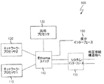
図2を参照すると、アプリケーション処理(「AP」)または通信ノード100用の例示的アーキテクチャのブロック図が示されている。APノード100は、たとえば図1のデジタル通信システム10などのアプリケーションのコンテキストで1つまたは複数の機能を実行する。
Referring to FIG. 2, a block diagram of an exemplary architecture for application processing (“AP”) or
高速データ通信をサポートするためにAPノード100は、マルチ・プロセッサを利用することができる。図示されるように、APノード100は、第1および第2のネットワーク・プロセッサ110および120を含み、そのうち少なくとも1つが、セルおよび/またはパケット情報を受け取る。さらに、APノード100はまた、汎用プロセッサ130を含み、汎用プロセッサ130は、ネットワーク・プロセッサ110および120と共に、専用スイッチ140を介して互いに結合されまた相互接続構造物(図示せず)に結合される。図示されるように、専用スイッチ140は、たとえば、特にEthernetベース方式を使用して相互接続構造物が提供される場合、Ethernetスイッチによって実現することができる。
In order to support high-speed data communication, the
Ethernetスイッチ140は、APノード100の一部分としていくつかの機能を実行する。まず、Ethernetスイッチ140は、システム・インターフェース150を含めた相互接続構造物への冗長インターフェース、ならびに、保守インターフェース160を含む、APノード100にある複数の「ポート」間の相互接続を提供する。さらに、スイッチ140は、APノード100にある複数の「ポート」およびプロセッサ110、120、130の間の相互接続を提供する。
The
さらに、Ethernetスイッチ140は、ルーティング装置としても機能する。この場合、スイッチ140は、ポート間でのEthernetパケットのルーティングおよび転送を行う。これらのポートは、通常は、L2(Ethernet)またはL3(インターネット・プロトコル)の1組のルーティング命令に基づくものとすることができる。この場合、汎用プロセッサ130は、スイッチ140のためのトラフィック制御メカニズムとして働くことができることに留意されたい。
Further, the
Ethernetスイッチ140はまた、APノード100のためのフェイル・オーバ機能を提供することもできる。この場合、スイッチ140は、システム・インターフェース150など相互接続構造物への冗長インターフェースのフェイル・オーバを取り扱うのを助けることができる。さらに、スイッチ140は、アクティブ・ポートの障害を検出した場合にアクティブ・ポートから待機ポートに切り替えを行うことができる。
The
Ethernetスイッチ140は、APノード100が求める他の機能を実行することもできることに留意されたい。このような機能は、デジタル通信システム内のアプリケーションのコンテキストにおいてAPノード100のそのアプリケーションが与えられた場合に特に重要になり得る。これらの機能には、たとえばバッファリング、サービス・クラスのサポート、およびフロー制御が含まれ得る。
Note that the
APノード100内のEthernetスイッチ140の使用は、いくつかの有益な目的に役立つが、注意すべき制限が依然として残る。まず、専用スイッチが、かなりの量の電力を消費する。したがって、消費電力および放熱の問題に注意が必要なことがある。さらに、各専用スイッチのコスト、およびAPノードの回路基板上で各スイッチが消費するスペースが、システムの設計、容量、および効率に影響を与えるおそれもある。
Although the use of the
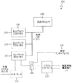
図3を参照すると、本発明の実施形態が示されている。より詳細には、図2のAPノード100内の専用(たとえばEthernet)スイッチ140を使用することに関連した制限に対処するためのルーティング・アーキテクチャ200が示されている。ルーティング・アーキテクチャ200では、より分散的な手法に有利にアーキテクチャにおける専用スイッチ装置を不要にする。
Referring to FIG. 3, an embodiment of the present invention is shown. More particularly, a
ルーティング・アーキテクチャ200の柔軟な性質により、APノードが複数のセルまたはパケット・プロトコルのネイティブ移送を同時にサポートするのを可能にすることができることに留意されたい。この柔軟性の向上により、1つ(または複数の)APノードが、以前はこの周知の技術分野で不可能であった追加のアプリケーションを扱うことができるようになる。これに関連して、ルーティング・アーキテクチャ200は、たとえば同時に(たとえばEthernet、IP、ATMの)1つ(または複数)のセルおよび/またはパケットのルーティングおよび/または転送を、並列にアーキテクチャ200内で行うことができる。
Note that the flexible nature of the
ルーティング・アーキテクチャ200は、専用スイッチ要素を必要とせずにセルおよび/またはパケットのルーティングおよび/または転送を行うための機能の拡張セット(superset)を提供する。この目的のために、ルーティング・アーキテクチャ200は、相互接続構造物210を介してセルおよび/またはパケット情報を受け取る。相互接続構造物210は、ルーティング・アーキテクチャ200に反映されるように、APノードを他のAPノード(図示せず)に結合する。この開示において、セルおよび/またはパケット情報を相互接続210から受け取るルーティング・アーキテクチャ200について述べたが、セルおよび/またはパケット情報はまた、以下で開示するルーティング・アーキテクチャ200を形成するコンポーネントによって処理されたあとに相互接続構造物210に送出することもできることに留意されたい。したがって、本明細書では、受け取る(receiving)という語への言及は、送出すること(transmitting)を含むことがある。
The
受け取られたセルおよび/またはパケット情報は、システム・インターフェース220を介して、ルーティング・アーキテクチャ200内にも、その外へも供給することができる。セルおよび/またはパケット情報はまた、保守インターフェース230によって受け取ることもできる。ある実施形態では、保守インターフェース230が受け取るセルおよび/またはパケット情報を、たとえば動作および/または保守タイプ情報に対応するものとすることができる。それとは対照的に、システム・インターフェース220が受け取るセルおよび/またはパケット情報を、たとえばベアラ移送パス処理および/または呼出し制御タイプ情報に対応するものとすることもできる。
Received cell and / or packet information can be provided in and out of the
上記のセルおよび/またはパケット情報を処理するために、ルーティング・アーキテクチャ200は、複数のネットワーク処理(「NP」)装置240、250、260を含む。より詳細には、1つまたは複数のNP装置240、250および/または260が、システム・インターフェース220を介して相互接続構造物210からセルおよび/またはパケット情報を受け取るように指定することができる。したがって、システム・インターフェース220は、異なるAPノード間の通信を促進するために、少なくとも1つのNP装置240、250および/または260を構造物210に結合することができる。
In order to process the cell and / or packet information described above, the
NP装置240、250、および260によって担われる機能をサポートするために、ルーティング・アーキテクチャ200は、共有バス構造270を含むこともできる。共有バス構造270は、ルーティング・アーキテクチャ200に対応する同じAPノード上で、各NP装置240、250、260を互いに結合する手段を提供する。ある実施形態では、共有バス構造270は、周辺コンポーネント相互接続(「PCI」)バスを含むことができる。
To support the functions performed by
ルーティング・アーキテクチャ200は、汎用プロセッサ280を含むこともできる。汎用プロセッサ280は、各NP装置240、250、260の制御を含めた多数の機能を果たすことができる。さらに、汎用プロセッサ280はまた、ルーティング・アーキテクチャ200によって実現される、APノード上での保守を行うこともできる。これらの機能をサポートするために、汎用プロセッサ280は、共有バス構造270と結合することもできる。
The
上記の構成によって、NP装置240、250および/または260は、追加の機能を実行することもできる。1つまたは複数のNP装置240、250および/または260は、たとえば、ルーティング・アーキテクチャ200内で、受け取ったセルおよび/またはパケット情報の宛先を決定することができる。ある実施形態では、1つまたは複数の格納されたルーティング規則ならびに/あるいはセルおよび/またはパケット情報(たとえばパケット・タイプ、L2、L3、宛先アドレス、ソース・アドレス、および他のパケット情報)の個々の特性に応じて、セルおよび/またはパケット情報の宛先を決定することができる。その後、少なくとも1つのNP装置240、250、および/または260は、セルおよび/またはパケット情報を決定された宛先に転送または送ることができる。
With the above configuration, the
1つまたは複数のNP装置240、250、および/または260は、ピア・ツー・ピアのルーティングをサポートすることができることに留意されたい。ここではピア・ツー・ピア・ルーティングは、1つのNP装置240、250、または260と、1つまたは複数の他のNP装置240、250、および/または260との間でのルーティングを意味することがある。同様に、ピア・ツー・ピア・ルーティングには、汎用プロセッサ280と1つまたは複数のNP装置240、250、および/または260の間でのルーティングが含まれ得る。
Note that one or
ルーティング・アーキテクチャ200はまた、直接送達機能(direct delivery feature)をサポートすることもできる。この場合、1つ(または複数)のセルおよび/またはパケットを、汎用プロセッサ280または1つのNP装置240、250、または260から、1つまたは複数の他の処理装置(たとえば、他のNP装置240、250、および/または260、ならびに/あるいは汎用プロセッサ280)のメモリ内に、たとえば共有バス構造270を介して直接送達することができる。この構成によって、送達された1つ(または複数)のセルまたはパケットは、割り込みをすることなく(あるいは1つまたは複数の他のこのような処理装置を作動させることなく)到着することができ、それによりこの時間に他の情報を処理する(またはスリープ・モード動作になる)ことができるようになる。したがって、他のこのような処理装置の1つまたは複数が作動可能(またはウェイク)であるとき、1つ(または複数)の特定のセルまたはパケットが、その後続の内部処理を早めるために待機している。代替形態では、1つ(または複数)の特定のセルまたはパケットは、1つまたは複数の他の処理装置のメモリ内に直接到着することができ、これにより、そこで割込み(またはウェイク・アップ)ルーチンを開始するようにする。
The
NP装置240、250、および/または260、ならびに/あるいは汎用プロセッサ280の間でのセルおよび/またはパケット情報のルーティングおよび/または転送は、アーキテクチャ200の柔軟な構造を活用するためのプログラム可能性の諸側面を利用していることに留意されたい。これに関連して、格納されたルーティング規則は、単純なものから複雑なものに及び得る。しかし、これらのルーティング規則は、ソフトウェアで実施することができ、したがって更新および/またはアップグレードすることができ、さらに優れた柔軟性を提供する。
Routing and / or forwarding of cell and / or packet information between
ルーティング・アーキテクチャ200は、NP装置レベルにおける深いパケット検査を可能にする。この場合、深いパケット検査により、アーキテクチャ200は、セルおよび/またはパケット内のフィールドの一部もしくは全部へルーティング・ソフトウェアがアクセスするのを可能にすることができる。次いでルーティングおよび/または転送を、たとえばパケット内の複数のプロトコル層から得た単一または複数のフィールドを使用して実行することができる。たとえば、同じレイヤ3宛先IPアドレスを有する複数のEthernetパケットを、レイヤ4およびより高位のパラメータ(たとえばUDPポート番号)に基づいて異なるNP装置240、250、および/または260に送ることができる。
The
ある実施形態では、ルーティング・アーキテクチャ200は、マルチプレクサ290を含むこともできる。マルチプレクサ290は、システム・インターフェース220および保守インターフェース230を1つまたは複数のNP装置240、250、および/または260に結合する。この構成により、マルチプレクサ290は、少なくとも1つのNP装置240、250、および/または260が本明細書に詳述される様々な処理機能を実行できるようにするために、システム・インターフェース220および保守インターフェース230が受け取ったセルおよび/またはパケット情報から多重化されたストリームを作成する。
In some embodiments, the
ルーティング・アーキテクチャ200は、少なくとも1つの外部システム入出力インターフェース300を含むこともできる。外部システム入出力インターフェース300は、1つまたは複数のNP装置240、250、および/または260に結合することができる。ある外部システム入出力インターフェース300について、1つまたは複数の移送メカニズム形式をサポートすることが必要とされることがある。したがって、外部システム入出力インターフェース300は、たとえば非同期転送モード、インターネット・プロトコル、およびフレーム・リレーの少なくとも1つをサポートすることができる。
The
例示的実施形態
本発明のアーキテクチャに基づくAPノードでは、セルまたはパケットのルーティングおよび/または転送は、NP装置のうち1つが実行すべきである。APノードの典型的アプリケーションでは、このルーティングおよび/または転送機能は、NP装置のリソースのサブセットしか必要としないことがある。その結果、他の処理のために未確認の量のリソースがNP装置内で利用可能なまま残ることがある。
Exemplary Embodiment In an AP node based on the architecture of the present invention, cell or packet routing and / or forwarding should be performed by one of the NP devices. In a typical application of an AP node, this routing and / or forwarding function may only require a subset of the resources of the NP device. As a result, an unconfirmed amount of resources may remain available in the NP device for other processing.
図3の実施形態を参照すると、たとえば少なくともNP装置240が、場合によっては任意選択のマルチプレクサ290を介して、システム・インターフェース220または保守インターフェース230から来るパケットまたはセルを受け取ることができる。少なくとも1つのNP装置240が、たとえば他のNP装置250および/またはNP装置260、ならびに/あるいは汎用プロセッサ280など、所与のセルおよび/またはパケットのための宛先を決定し、共有バスまたは他の好都合な相互接続手段を介してこのセルおよび/またはパケットを指定された装置に移動すべきである。所与のセルおよび/またはパケットのための宛先が、NP装置自体である場合は、パケットは、ローカルに転送すべきである。セルおよび/またはパケット情報の移動が行われるプロセスは、ローカルに格納された1組のルーティング規則、および、場合によってはソース・ポートなどセルまたはパケットの他の特性に基づくべきである。
Referring to the embodiment of FIG. 3, for example, at
逆方向においては、たとえば少なくともNP装置240が、共有バスを介して残りのプロセッサからセルおよび/またはパケットを収集することができる。したがって、たとえば少なくともNP装置240は、次いでローカルに格納されたルーティング規則に基づいて適切なポートにセルおよび/またはパケットを転送することができる。この場合、少なくともNP装置240は、プロセッサ間でのピア・ツー・ピア・ルーティングをサポートする能力を有することもできる。
In the reverse direction, for example, at least the
図2のEthernetスイッチ140などの専用スイッチにより以前は実行された重要な機能が、たとえば、共有バス構造および場合により任意選択のマルチプレクサを介して、図3のNP装置240など少なくとも1つのネットワーク・プロセッサ内のルーティング・ソフトウェア間で分散できることがわかる。これに関連して、共有バス構造および任意選択のマルチプレクサは、冗長システム・インターフェース、ローカル保守インターフェース、およびマルチ・プロセッサを含めた様々な基板上の「ポート」間での相互接続を扱うことができる。さらに、セルおよび/またはパケットの転送および/またはルーティングは、NP装置の1つにある処理リソースのサブセットで実行することができる。同様に、冗長システム・インターフェースのフェイル・オーバの処理を、NP装置の1つと任意選択のマルチプレクサの組み合わせによって行うことができる。最後に、バッファリング、サービス・クラスのサポート、およびフロー制御などの機能も、NP装置内の処理リソースのサブセットによって実行することができる。
An important function previously performed by a dedicated switch, such as
本発明のルーティング・アーキテクチャでは、図2のEthernetスイッチ140などの専用スイッチなしで、電力バジェット、放熱、基板のスペース、およびコストに関して性能の改善を示すことができることに留意されたい。このような性能の向上が与えられたとすると、より多くのプロセッサ要素を有するAPノードを設計することが可能になり、さらにシステムの性能が高まる。上記に概説した性能の向上に加えて、このアーキテクチャは、柔軟性の向上を示し、それにより、このアーキテクチャで設計されたアプリケーション・プロセッサが、新しいアプリケーションを扱うことが可能になる。
Note that the routing architecture of the present invention can show performance improvements in terms of power budget, heat dissipation, board space, and cost without a dedicated switch such as the
このアーキテクチャにおいて専用スイッチの必要性を無くすことにより、APノードが追加の機能を実行することが可能になる。たとえば、本発明の成果として、APノードは、同時に、複数のセルまたはパケット移送プロトコル、ならびに、移送プロトコルでのそれらの転送をサポートすることを可能にすることができる。このことは、基板上のプロセッサのうちの1つのプロセッサのプログラム可能素子に実装されるセルまたはパケットのルーティングおよび/または転送メカニズムに帰すことができる。 By eliminating the need for a dedicated switch in this architecture, the AP node can perform additional functions. For example, as an outcome of the present invention, an AP node may be able to simultaneously support multiple cell or packet transport protocols and their transfer in transport protocols. This can be attributed to a cell or packet routing and / or forwarding mechanism implemented in a programmable element of one of the processors on the board.
本発明のルーティング・アーキテクチャの柔軟性はいくつかの利点を持つ。第1に、このアーキテクチャを利用しているAPノードは、複数のセルまたはパケット移送メカニズムをサポートすることができ、セルおよびパケットは、そのネイティブ・フォーマットで移送される。これにより、複数のフォーマットをサポートするためにカプセル化を使用してシステム全体にわたる性能の向上を提供することができる。第2に、本発明によるAPノードは、追加のアプリケーションをサポートする能力を有することができる。APノードが、たとえばインターフェース・プロセッサなどの外部システムの入出力へのインターフェースを必要とするアプリケーションをサポートするように構成することもできることは容易に理解することができる。 The flexibility of the routing architecture of the present invention has several advantages. First, AP nodes utilizing this architecture can support multiple cell or packet transport mechanisms, with cells and packets being transported in their native format. This can provide improved performance across the entire system using encapsulation to support multiple formats. Second, an AP node according to the present invention can have the ability to support additional applications. It can be readily appreciated that the AP node can also be configured to support applications that require an interface to an input / output of an external system, such as an interface processor.
さらに、本発明のルーティング・アーキテクチャは、パケット・ヘッダ情報の事前除去(pre−stripping)もサポートすることができる。より詳細には、ヘッダ情報を利用する必要なく、APノードを形成する処理装置の間でパケットをルーティングおよび/または転送することができる。これは、以前に使用されていた他のアーキテクチャの専用スイッチ(たとえば図2のEthernetスイッチ140)とは対照的である。
Further, the routing architecture of the present invention can also support pre-stripping of packet header information. More specifically, packets can be routed and / or forwarded between processing devices forming an AP node without having to use header information. This is in contrast to other architecture dedicated switches previously used (eg,
NP装置240、250、および/または260、共有バス構造270、ならびに汎用プロセッサ280はそれぞれ、ルーティング・アーキテクチャ200の柔軟性を促進するように構成することができることに留意されたい。上記に述べたように、ルーティング・アーキテクチャ200は、同時および/または並列に、(1つまたは複数の)セルおよび/またはパケットをルーティングおよび/または転送することができる。したがって、アーキテクチャ200の1つ(または複数)のセルおよび/またはパケットのデータを、NP装置240、250、および/または260、共有バス構造270、ならびに/あるいは汎用プロセッサ280の間で移動させることができる。
Note that the
本発明の他の実施形態では、本明細書に詳述したルーティングおよび/または転送メカニズムがEthernetパケットに対し働いていた場合、ATMセルをある適切な物理インターフェースを介して移送するために、ATMインターフェース・ブロックを外部システム入出力に結合することができる。この場合、ATMインターフェース・ブロックは、ルーティングおよび/または転送メカニズムが実装され得るネットワーク・プロセッサの1つに結合することもできる。この例では、ネットワーク・プロセッサへの接続手段はたとえばUtopiaバスによって実現することが有利になり得る。 In other embodiments of the invention, if the routing and / or forwarding mechanisms detailed herein are working for Ethernet packets, the ATM interface may be used to transport ATM cells over some suitable physical interface. • Blocks can be coupled to external system I / O. In this case, the ATM interface block can also be coupled to one of the network processors where routing and / or forwarding mechanisms can be implemented. In this example, it may be advantageous to implement the connection means to the network processor, for example by means of a Utopia bus.
本発明のルーティング・アーキテクチャの動作は下記の通りである。最初に、ネットワーク・プロセッサの1つを、追加の移送手段(たとえばUtopia)をサポートするようにプログラムし、セルが到着するための適切な宛先プロセッサを決定するための追加の1組のローカルに格納されるルーティング規則用に使用することができる。この場合、次いで識別されたネットワーク・プロセッサは、共有バス構造などを介してセルを転送することができる。セルが、その1つのネットワーク・プロセッサ自体を宛先とする場合、このセルはローカルで転送することができる。 The operation of the routing architecture of the present invention is as follows. Initially, one of the network processors is programmed to support additional transport means (eg, Utopia) and stored in an additional set of locals to determine the appropriate destination processor for the cell to arrive. Can be used for routing rules. In this case, the subsequently identified network processor can transfer the cell, such as via a shared bus structure. If a cell is destined for that one network processor itself, this cell can be transferred locally.
逆方向では、1つのネットワーク・プロセッサが、共有バスを介して他のプロセッサからセルを収集することができる。ローカルに格納されたルーティング規則を検査したあと、その1つのネットワーク・プロセッサは、セルがATMインターフェース・ブロック宛であると決定することができる。その後、その1つのネットワーク・プロセッサは、たとえばUtopiaバスを介してセルが転送されるのを可能にすることができる。 In the reverse direction, one network processor can collect cells from other processors over a shared bus. After examining the locally stored routing rules, the one network processor can determine that the cell is destined for the ATM interface block. The one network processor can then allow the cells to be transferred, for example via the Utopia bus.
例示的な実施形態を参照して具体的に本発明を説明したが、本明細書は限定的な意味において解釈されることを意図するものではない。本発明について説明したが、例示的実施形態の様々な修正形態、ならびに本発明の追加の実施形態は、本明細書に添付の特許請求の範囲に記載する本発明の趣旨から逸脱することなく、本明細書を参照する当業者には明らかであることを理解されたい。したがって、この開示の利益を受ける当業者に理解されるように、ここに記載のシステムを実装し使用するために必要な処理回路は、特定用途向け集積回路、ソフトウェア駆動処理回路、ファームウェア、プログラム可能論理デバイス、ハードウェア、個別部品、または上記のコンポーネントの取り合わせに実装することもできる。これらおよび他の様々な修正形態、取り合わせ、および方法は、本明細書に図示し説明した例示的適用に厳密に従うことなく、また本発明の趣旨および範囲から逸脱することなく、本発明に行うことができることは、当業者には簡単に理解されよう。したがって、添付の特許請求の範囲は、本発明の真の範囲に含まれるどのような修正形態または実施形態も包含することが企図される。 Although the invention has been specifically described with reference to illustrative embodiments, this description is not intended to be construed in a limiting sense. Although the invention has been described, various modifications of the exemplary embodiments, as well as additional embodiments of the invention, may be made without departing from the spirit of the invention as set forth in the claims appended hereto. It should be understood that those skilled in the art having reference to this specification will be apparent. Accordingly, as will be appreciated by one of ordinary skill in the art having the benefit of this disclosure, the processing circuitry required to implement and use the system described herein is application specific integrated circuit, software driven processing circuitry, firmware, programmable It can also be implemented as a logical device, hardware, discrete components, or a combination of the above components. These and various other modifications, arrangements, and methods are made to the present invention without strictly following the exemplary applications shown and described herein, and without departing from the spirit and scope of the present invention. Those skilled in the art will readily understand that this is possible. Accordingly, the appended claims are intended to cover any modifications or embodiments that fall within the true scope of the present invention.
Claims (10)
構造物を介して相互接続された少なくとも1つのノードを含み、前記少なくとも1つのノードは、
前記セルと前記パケット情報の少なくとも1つを受け取り、前記ノード内で前記セルと前記パケット情報の宛先を決定し、前記セルと前記パケット情報とを宛先にルーティングするかまたは転送するかの少なくとも一方を行う、複数のネットワーク処理装置の少なくとも1つと、
前記各ネットワーク処理装置を互いに結合する共有バス構造と、
ノード間の通信をサポートするために前記ネットワーク処理装置の少なくとも1つを前記構造物に結合するインターフェースとを含むことを特徴とするシステム。 A digital communication system for processing at least one of cell and packet information,
Including at least one node interconnected via a structure, the at least one node comprising:
Receiving at least one of the cell and the packet information, determining a destination of the cell and the packet information within the node, and at least one of routing or forwarding the cell and the packet information to a destination Performing at least one of a plurality of network processing devices;
A shared bus structure for coupling the network processing devices to each other;
An interface coupling at least one of the network processing devices to the structure to support communication between nodes.
At least one external system input / output interface, wherein the external system input / output interface supports at least one transport mechanism type, wherein the at least one transport mechanism type includes an asynchronous transfer mode, an internet protocol, and a frame relay The digital communication system according to claim 1, comprising at least one of the following.
Applications Claiming Priority (1)
| Application Number | Priority Date | Filing Date | Title |
|---|---|---|---|
| US10/815,129 US20050220090A1 (en) | 2004-03-31 | 2004-03-31 | Routing architecture |
Publications (1)
| Publication Number | Publication Date |
|---|---|
| JP2005295557A true JP2005295557A (en) | 2005-10-20 |
Family
ID=34887739
Family Applications (1)
| Application Number | Title | Priority Date | Filing Date |
|---|---|---|---|
| JP2005100424A Withdrawn JP2005295557A (en) | 2004-03-31 | 2005-03-31 | Routing architecture |
Country Status (6)
| Country | Link |
|---|---|
| US (1) | US20050220090A1 (en) |
| EP (1) | EP1583300B1 (en) |
| JP (1) | JP2005295557A (en) |
| KR (1) | KR20060044740A (en) |
| CN (1) | CN1677961A (en) |
| DE (1) | DE602005000183T2 (en) |
Cited By (1)
| Publication number | Priority date | Publication date | Assignee | Title |
|---|---|---|---|---|
| JP2022132603A (en) * | 2017-10-12 | 2022-09-08 | ロックポート ネットワークス インコーポレイテッド | direct interconnect gateway |
Families Citing this family (3)
| Publication number | Priority date | Publication date | Assignee | Title |
|---|---|---|---|---|
| US20060153085A1 (en) * | 2004-12-27 | 2006-07-13 | Willins Bruce A | Method and system for recovery from access point infrastructure link failures |
| US9621375B2 (en) | 2006-09-12 | 2017-04-11 | Ciena Corporation | Smart Ethernet edge networking system |
| KR100793632B1 (en) * | 2006-08-23 | 2008-01-10 | 전자부품연구원 | Module based car media server device and car media system using same |
Family Cites Families (19)
| Publication number | Priority date | Publication date | Assignee | Title |
|---|---|---|---|---|
| US5983260A (en) * | 1995-07-19 | 1999-11-09 | Fujitsu Network Communications, Inc. | Serial control and data interconnects for coupling an I/O module with a switch fabric in a switch |
| US6658021B1 (en) * | 1998-06-19 | 2003-12-02 | Juniper Networks, Inc. | Method and system for encapsulating/decapsulating data on a per channel basis in hardware |
| US6785277B1 (en) * | 1998-08-06 | 2004-08-31 | Telefonaktiebolget Lm Ericsson (Publ) | System and method for internodal information routing within a communications network |
| US6839345B2 (en) * | 1999-12-17 | 2005-01-04 | Texas Instruments Incorporated | MAC/PHY interface |
| EP1187497A3 (en) * | 2000-09-11 | 2002-11-20 | Alcatel USA Sourcing, L.P. | Service creation and service logic execution environment for a network processor |
| US6944155B2 (en) * | 2001-03-05 | 2005-09-13 | International Business Machines Corporation | Apparatus for filtering inter-node communication in a data processing system |
| US6993023B2 (en) * | 2001-04-27 | 2006-01-31 | The Boeing Company | Parallel analysis of incoming data transmissions |
| US7224689B2 (en) * | 2001-08-17 | 2007-05-29 | Sun Microsystems, Inc. | Method and apparatus for routing of messages in a cycle-based system |
| US7676588B2 (en) * | 2001-10-05 | 2010-03-09 | International Business Machines Corporation | Programmable network protocol handler architecture |
| US7342883B2 (en) * | 2002-04-25 | 2008-03-11 | Intel Corporation | Method and apparatus for managing network traffic |
| US7171505B2 (en) * | 2002-05-02 | 2007-01-30 | International Business Machines Corporation | Universal network interface connection |
| US7366179B2 (en) * | 2002-06-21 | 2008-04-29 | Adtran, Inc. | Dual-PHY based integrated access device |
| US7468979B2 (en) * | 2002-12-20 | 2008-12-23 | Force10 Networks, Inc. | Layer-1 packet filtering |
| US6838345B2 (en) * | 2002-12-23 | 2005-01-04 | Macronix International Co., Ltd. | SiN ROM and method of fabricating the same |
| US20040151170A1 (en) * | 2003-01-31 | 2004-08-05 | Manu Gulati | Management of received data within host device using linked lists |
| US7564860B2 (en) * | 2003-05-08 | 2009-07-21 | Samsung Electronics Co., Ltd. | Apparatus and method for workflow-based routing in a distributed architecture router |
| US7324518B2 (en) * | 2003-06-05 | 2008-01-29 | International Business Machines Corporation | Method and apparatus for transmitting wake-up packets over a network data processing system |
| US7440469B2 (en) * | 2003-10-14 | 2008-10-21 | Broadcom Corporation | Descriptor write back delay mechanism to improve performance |
| US7058424B2 (en) * | 2004-01-20 | 2006-06-06 | Lucent Technologies Inc. | Method and apparatus for interconnecting wireless and wireline networks |
-
2004
- 2004-03-31 US US10/815,129 patent/US20050220090A1/en not_active Abandoned
-
2005
- 2005-03-15 DE DE602005000183T patent/DE602005000183T2/en not_active Expired - Fee Related
- 2005-03-15 EP EP05251543A patent/EP1583300B1/en not_active Expired - Lifetime
- 2005-03-25 KR KR1020050024849A patent/KR20060044740A/en not_active Withdrawn
- 2005-03-30 CN CNA2005100595982A patent/CN1677961A/en active Pending
- 2005-03-31 JP JP2005100424A patent/JP2005295557A/en not_active Withdrawn
Cited By (2)
| Publication number | Priority date | Publication date | Assignee | Title |
|---|---|---|---|---|
| JP2022132603A (en) * | 2017-10-12 | 2022-09-08 | ロックポート ネットワークス インコーポレイテッド | direct interconnect gateway |
| JP7357123B2 (en) | 2017-10-12 | 2023-10-05 | ロックポート ネットワークス インコーポレイテッド | direct interconnect gateway |
Also Published As
| Publication number | Publication date |
|---|---|
| EP1583300B1 (en) | 2006-10-18 |
| EP1583300A1 (en) | 2005-10-05 |
| DE602005000183D1 (en) | 2006-11-30 |
| KR20060044740A (en) | 2006-05-16 |
| US20050220090A1 (en) | 2005-10-06 |
| CN1677961A (en) | 2005-10-05 |
| DE602005000183T2 (en) | 2007-08-23 |
Similar Documents
| Publication | Publication Date | Title |
|---|---|---|
| JP3449294B2 (en) | Multiprotocol processing device, line interface, and multiprotocol switch system having the same | |
| US10015082B2 (en) | Providing non-interrupt failover using a link aggregation mechanism | |
| US6947433B2 (en) | System and method for implementing source based and egress based virtual networks in an interconnection network | |
| CN102377666B (en) | Flooding-based routing protocol having average-rate and burst-rate control | |
| KR100624681B1 (en) | Apparatus and method for combining forwarding tables in a distributed architecture router | |
| JP5598688B2 (en) | Network system, control device, and optimum route control method | |
| US20020051427A1 (en) | Switched interconnection network with increased bandwidth and port count | |
| JP2004135106A (en) | Packet communication device | |
| JP2014511091A (en) | Condensed core energy efficient architecture for WANIP backbone | |
| US20110286422A1 (en) | Electronic device and method of communication resource allocation | |
| US8996724B2 (en) | Context switched route look up key engine | |
| CN100379195C (en) | Data exchange with soft configuration | |
| US6965602B2 (en) | Switch fabric capable of aggregating multiple chips and links for high bandwidth operation | |
| EP1583300B1 (en) | Routing architecture | |
| JP4409776B2 (en) | Establish internal control path of ATM node | |
| CN116781618A (en) | Route generation method, data message forwarding method and device | |
| US20050249229A1 (en) | Dynamically scalable edge router | |
| CN116762323A (en) | A switching system, switching network and switching node | |
| Tzeng | Multistage-based switching fabrics for scalable routers | |
| JP4669442B2 (en) | Packet processing system, packet processing method, and program | |
| CN113132252B (en) | Injection for unequal link connections in an internal switching fabric | |
| US20220368619A1 (en) | Computing system, computing processor and data processing method | |
| CN101035079B (en) | Asynchronous forwarding method, system and equipment | |
| KR20070059447A (en) | Packet processing apparatus, method and apparatus for applying multiple switching port support structure | |
| Mandviwalla et al. | DRA: A dependable architecture for high-performance routers |
Legal Events
| Date | Code | Title | Description |
|---|---|---|---|
| A621 | Written request for application examination |
Free format text: JAPANESE INTERMEDIATE CODE: A621 Effective date: 20080324 |
|
| A761 | Written withdrawal of application |
Free format text: JAPANESE INTERMEDIATE CODE: A761 Effective date: 20090911 |