JP2005295545A - Color device profile having buffered lookup table - Google Patents
Color device profile having buffered lookup table Download PDFInfo
- Publication number
- JP2005295545A JP2005295545A JP2005087483A JP2005087483A JP2005295545A JP 2005295545 A JP2005295545 A JP 2005295545A JP 2005087483 A JP2005087483 A JP 2005087483A JP 2005087483 A JP2005087483 A JP 2005087483A JP 2005295545 A JP2005295545 A JP 2005295545A
- Authority
- JP
- Japan
- Prior art keywords
- lookup table
- color
- node
- input
- value
- Prior art date
- Legal status (The legal status is an assumption and is not a legal conclusion. Google has not performed a legal analysis and makes no representation as to the accuracy of the status listed.)
- Pending
Links
- 239000011159 matrix material Substances 0.000 claims description 10
- 238000000034 method Methods 0.000 claims description 10
- 230000003362 replicative effect Effects 0.000 claims 1
- 238000012545 processing Methods 0.000 description 12
- 238000006243 chemical reaction Methods 0.000 description 11
- 238000010586 diagram Methods 0.000 description 8
- 230000001419 dependent effect Effects 0.000 description 6
- 238000003491 array Methods 0.000 description 1
- 230000006870 function Effects 0.000 description 1
- 239000010410 layer Substances 0.000 description 1
- 238000012986 modification Methods 0.000 description 1
- 230000004048 modification Effects 0.000 description 1
- 238000012544 monitoring process Methods 0.000 description 1
- 238000012856 packing Methods 0.000 description 1
- 239000002356 single layer Substances 0.000 description 1
- 239000007787 solid Substances 0.000 description 1
Images

Classifications
-
- H—ELECTRICITY
- H04—ELECTRIC COMMUNICATION TECHNIQUE
- H04N—PICTORIAL COMMUNICATION, e.g. TELEVISION
- H04N1/00—Scanning, transmission or reproduction of documents or the like, e.g. facsimile transmission; Details thereof
- H04N1/46—Colour picture communication systems
- H04N1/56—Processing of colour picture signals
- H04N1/60—Colour correction or control
- H04N1/6016—Conversion to subtractive colour signals
- H04N1/6019—Conversion to subtractive colour signals using look-up tables
Landscapes
- Engineering & Computer Science (AREA)
- Multimedia (AREA)
- Signal Processing (AREA)
- Image Processing (AREA)
- Facsimile Image Signal Circuits (AREA)
- Color, Gradation (AREA)
- Color Image Communication Systems (AREA)
- Processing Of Color Television Signals (AREA)
Abstract
Description
本発明の開示は全体として、プリンタ・プロファイル(profiles)に向けられる。 The present disclosure is generally directed to printer profiles.
カラー装置プロファイルは、1つの装置の色空間のためにフォーマットされたカラー画像データを、他の装置の色空間のためにフォーマットされた色画像データに変換するために広く用いられている。例えば、国際色コンソーシアム(ICC)作業フローは、モニターのために赤−緑−青(RGB)色空間でフォーマットされた色画像データの、プロファイル接続空間(PCS)と呼ばれる装置独立の色空間への変換、及びその後の、カラー・プリンタのための、CMYK空間でフォーマットされた色画像データへの変換を要求する。
計算の制限の結果として、クリーンな主の、及び/又は、第2の出力カラー、を生成することは困難であり得る。
Color device profiles are widely used to convert color image data formatted for the color space of one device into color image data formatted for the color space of another device. For example, the International Color Consortium (ICC) workflow allows the conversion of color image data formatted in a red-green-blue (RGB) color space for monitoring into a device-independent color space called a profile connection space (PCS). Requests conversion and subsequent conversion to color image data formatted in CMYK space for a color printer.
As a result of computational limitations, it can be difficult to produce a clean primary and / or secondary output color.
プロファイル接続空間(PCS:profile connection space)値を、目的地の(destination)色空間値に変換する方法であって、PCS値を使用して、3次元の各々の中で(0+INT−E0)から(MAX−INT+E1)の範囲を持つルックアップ・テーブル入力を生成するステップ、ルックアップ・テーブル入力及びルックアップ・テーブルを用いて、目的地の色空間値を生成するステップであって、ルックアップ・テーブルが、G×G×G節点を含み、(G−2)×(G−2)×(G−2)節点を持つ内側部分、及び、内側部分を囲む[G×G×G−(G−2)×(G−2)×(G−2)]節点を持つ外側部分、を含むものであり、外側部分の節点が、内側部分の、対応する最も外側の節点の複製を備えるものである、ステップを含み、INTが、前記ルックアップ・テーブルのグリッド間隔であり、E0とE1の各々が、INTより小さく、MAXが正の整数である方法。 A method of converting a profile connection space (PCS) value to a destination color space value using (0 + INT-E0) in each of the three dimensions using the PCS value. Generating a lookup table input having a range of (MAX−INT + E1), generating a destination color space value using the lookup table input and the lookup table, comprising: The table includes G × G × G nodes, an inner portion having (G-2) × (G-2) × (G-2) nodes, and surrounding the inner portion [G × G × G− (G −2) × (G−2) × (G−2)] an outer part having a node, the node of the outer part comprising a copy of the corresponding outermost node of the inner part Including a step wherein INT is A grid spacing of Kkuappu table, each of E0 and E1 is less than INT, method MAX is a positive integer.
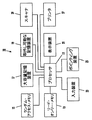
図1は、コンピュータ・システム内でここに開示される色変換パイプラインが利用される、当該コンピュータ・システム10の実施例の概略ブロック図である。コンピュータ・システムは、プロセッサ11、リード・オンリー・メモリ13、ランダム・アクセス・メモリ15、ディスク・ドライブのような大容量記憶装置17や、DVDドライブのような取外し可能な記憶装置19、を含む。コンピュータ・システムは更に、例えばカラー・モニタで有り得るディスプレイ21、ユーザ・コマンドを入力するためのキーボード又はタッチ・パッドのような入力装置23、ディスプレイ21の上に表示されたグラフカル・ユーザ・インターフェース又は他のオブジェクトにポインティングし、それを操作するための、マウス又はトラックボールのようなポインティング装置25、を含む。コンピュータ・システム10は、例えば、ローカル・エリア・ネットワークを介して、プリンタ27に接続され得る。コンピュータ・システム10は、スキャナ29にも接続され得る。
FIG. 1 is a schematic block diagram of an embodiment of a
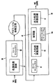
図2は、ソースの装置従属の色空間SCS入力値を、出力目的装置従属の色空間DSC出力値にマップ又は変換するために採用され得る色変換パイプラインの実施例の概略ブロック図である。ソース装置色空間SCSは、カラー・モニタのような表示装置のために、フォーマット又は構成され得る一方、目的装置の色空間DCSは、プリンタのようなハードコピー装置のためにフォーマット或いは構成され得る。ソース装置の色空間の例は、RGB(赤−緑−青)であり得る一方、目的装置色空間の例は、CMYK(シアン-マゼンタ-黄色-黒)であり得る。従って、例えば、カラー・モニタのためにフォーマットされたRGB入力色データは、プリンタのためにフォーマットされたCMYK出力色データにマップされ、或いは、変換される。 FIG. 2 is a schematic block diagram of an embodiment of a color conversion pipeline that may be employed to map or convert a source device-dependent color space SCS input value to an output destination device-dependent color space DSC output value. The source device color space SCS may be formatted or configured for a display device such as a color monitor, while the target device color space DCS may be formatted or configured for a hardcopy device such as a printer. An example source device color space may be RGB (red-green-blue), while an example target device color space may be CMYK (cyan-magenta-yellow-black). Thus, for example, RGB input color data formatted for a color monitor is mapped or converted to CMYK output color data formatted for a printer.
色空間変換パイプラインは、コンピュータ・オペレーティング・システムの色管理モジュール(CMM)で、或いは、例えば、ICC作業フローに従うアプリケーションで実施され得る。参照の容易化のために、本開示は、ソース装置従属のRGB色空間及び目的装置従属のCMYK色空間の文脈内にあり、他の色空間が採用され得ることが理解されるべきである。
色変換パイプラインは、RGB値のようなソース装置従属の色空間入力値を、プロファイル接続空間(PCS)値XYZにマップ又は変換する、装置からPCSへのプロファイル30を含む。装置からPCSへのプロファイル30は、例えば、色調の(tonal)再製カーブ(TRCs)31、及び、3×3マトリックス33を採用し得る。TRCs31は、PCS XYZ値を生成するためにマトリックス33によって乗算された、調整されたソース装置色空間値を提供する。装置からPCSへのプロファイル30は、装置特有のプロファイル(例えば、特定のスキャナ又はモニタのための)であり得るか、或いは、それは、sRGBのような準(quasi)スタンダード装置色空間であり得る。
The color space conversion pipeline may be implemented in a computer operating system color management module (CMM) or in an application that follows, for example, an ICC workflow. For ease of reference, it should be understood that the present disclosure is within the context of a source device dependent RGB color space and a target device dependent CMYK color space, and other color spaces may be employed.
The color conversion pipeline includes a device-to-
色変換パイプラインは更に、PCS値を、CMYKのような目的装置従属の色出力値にマップ或いは変換する、PCSから装置へのプロファイル40を含む。PCSから装置へのプロファイル40は、3×3マトリックス41、入力TRCs43、補間器(interpolator)45、及び、出力TRCs47を含む。3×3マトリックス41は、PCS値を、中間目的地(destination)装置の色空間ICSにマップし、入力TRCs43は、中間目的地装置の色値を調整して、調整された中間色値を、CMYKのような目的地装置の色空間値にマップする補間器45への入力を提供する。目的地装置の色空間値は、調整された目的地装置の色空間値を提供するために、出力TRCs47に従って調整され得る。
補間器45は、CMYKのような目的地装置の色値を含むカラー・ルックアップ・テーブル145を採用する。テーブル内の各CMYK値は、節点(node)と呼ばれ得、入力TRCs43によって提供された、TRC調整された中間色空間ICS内の対応する位置のためのCMYK値を含む。節点(nodes)の間の値(即ち、節点(nodes)と対応付けられたPCS値の間の、調整されたPCS値に対するCMYK値)は、補間を用いて計算される。PCSから装置へのプロファイル40は、例えば、特定のプリンタに特有であり得、適切な目的地装置の色空間値(例えば、CMYK)(これによって、出力装置が、PCS XYZデータによって指定された色を生成することになる)を生成する。入力TRCsの出力は、カラー・ルックアップ・テーブル145からデータを得るために、補間器45によって利用されるので、それは、カラー・ルックアップ・テーブルへの入力として、TRCsの出力へ参照するために便利であり得、そして、TRCsの値の範囲は、入力範囲と呼ばれ得る。入力TRCsは、テーブルとして実装され得、入力テーブルと呼ばれ得る。
The color conversion pipeline further includes a PCS-to-device profile 40 that maps or converts PCS values to destination device dependent color output values such as CMYK. The PCS-to-device profile 40 includes a 3 × 3
The interpolator 45 employs a color lookup table 145 that contains the color values of the destination device such as CMYK. Each CMYK value in the table may be referred to as a node and includes the CMYK value for the corresponding position in the TRC adjusted intermediate color space ICS provided by the input TRCs 43. Values between the nodes (ie, CMYK values for the adjusted PCS values between the PCS values associated with the nodes) are calculated using interpolation. The PCS-to-device profile 40 may be specific to a particular printer, for example, and may be an appropriate destination device color space value (eg, CMYK) (which allows the output device to specify the color specified by the PCS XYZ data. Will be generated). Since the output of the input TRCs is utilized by the interpolator 45 to obtain data from the color look-up table 145, it can be referenced to the output of the TRCs as an input to the color look-up table. The range of TRCs values can be convenient and can be referred to as the input range. Input TRCs may be implemented as a table and may be referred to as an input table.
PCSから装置へのプロファイル40のカラー・ルックアップ・テーブル145の色空間は、例えば、補間器45の入力範囲がソース装置の色空間SCS入力の範囲に対応するような形で、ソース装置の色空間SCSと整列(aligned with)され得る。これは、例えば、目的地装置プロファイル40の3×3マトリックスが、ソース装置プロファイル30の3×3マトリックス33の逆(inverse)となるように構成し、入力TRCs43が、ソース装置TRCs31の逆となるように構成することによって、実現され得る。このやり方で、PCS値は、マトリックス33の逆であるマトリックス41によって乗算される。そして、マトリックス41による乗算の結果は、ソース装置TRCs31の逆である入力TRCs43によって、調整され、或いは、線形化される。
従って、入力TRCs43の出力は、ほぼ、例えば、入力RGB値の近似複製(approximate replicas)、或いは、入力RGB値の近似スケールされた複製、を備える入力RGB値に対応する。換言すれば、入力TRCs43の出力は、処理によって導入されたいくらかの誤差項を伴った、入力RGB値の処理されたバージョン、或いは、スケールされたバージョンによって導入されたいくらかの誤差項(error terms)を伴った入力RGB値を含み得る。によって、例示的説明によって、入力RGB値は、8ビット・データであり得る一方、入力TRCsの値は、8ビット又は16ビット・データであり得る。従って、カラー・ルックアップ・テーブル145は、例えばRGB値をCMYK値にマップするルックアップ・テーブルを含む。
The color space of the PCS-to-device profile 40 color look-up table 145 is such that the input range of the interpolator 45 corresponds to the source device color space SCS input range, for example, Can be aligned with the space SCS. For example, the 3 × 3 matrix of the destination device profile 40 is configured to be inverse of the 3 × 3
Thus, the output of the input TRCs 43 approximately corresponds to the input RGB values comprising, for example, approximate replicas of the input RGB values or approximate scaled replicas of the input RGB values. In other words, the output of the input TRCs 43 is the error terms introduced by the processed or scaled version of the input RGB values, with some error terms introduced by the processing. May include input RGB values. By way of example, the input RGB values can be 8-bit data, while the values of the input TRCs can be 8-bit or 16-bit data. Thus, the color lookup table 145 includes a lookup table that maps RGB values to CMYK values, for example.
目的地装置プロファイル40のカラー・ルックアップ・テーブル145は、より特別に、最も外側のグリッド点又は節点に含まれるデータが、次に最も外側の(next to outermost)節点(即ち、最も外側の節点に最も近い内部節点)の複製であるような形で、拡張された(expanded)或いはバッファされた、カラー・ルックアップ・テーブルとして構成され得る。バッファされたカラー・ルックアップ・テーブル145は、外側の部分が内側部分を囲み、内側部分の最も近い節点の複製を含むような形で、内部領域又は部分(portion)及び外側領域又は部分を含み得る。換言すれば、外側部分の節点は、内側部分の最も外側の節点の複製である。説明的な例によって、外側の部分は、外側の部分の節点と対応付けられたインデックス或いはアドレスが、内側部分の最も外側の節点から間隔を空けられ、特定の内側部分の最も外側の節点の位置に依存して、それらが、一つあるいはそれ以上の軸に沿った1つのグリッド間隔INTによって複製するように、1つの節点の層を含む。
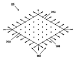
図3は、一般的に平行四辺形形状の参照境界245Bの上に、或いは、その内側に節点を備える、内部部分245A、及び、一般的に平行四辺形形状の境界245Bの外側に節点を備え、内側部分245Aを囲む外側部分245Cを含む、2次元バッファされたルックアップ・テーブル245の概略的説明である。外側部分245Cの節点は、内側部分245Aの最も外側の節点から、外側部分245Cの複製節点に引かれる矢印によって示されるように、内側部分245Aの最も外側の節点を複製する。換言すれば、内側部分245Aの最も外側の節点に含まれるデータは、外側の部分245Cの節点で複製される。
The color lookup table 145 for the destination device profile 40 more specifically indicates that the data contained in the outermost grid point or node is the next to outermost node (i.e., the outermost node). Can be configured as an expanded or buffered color look-up table in such a way that it is a duplicate of the nearest internal node. The buffered color lookup table 145 includes an inner region or portion and an outer region or portion such that the outer portion surrounds the inner portion and includes a copy of the nearest node of the inner portion. obtain. In other words, the node of the outer part is a duplicate of the outermost node of the inner part. By way of illustrative example, the outer part has an index or address associated with the outer part node spaced from the outermost node of the inner part, and the position of the outermost node of a particular inner part. Depending on the, they contain one nodal layer so that they replicate with one grid spacing INT along one or more axes.
FIG. 3 shows an
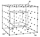
図4は、内側直線参照ボックス345Bの上、或いはその内側に節点を備える、内側部分345A、及び、内側部分345Aを囲む外側直線参照ボックス345Dの上の節点を備える外側部分345C、を含む3次元直線(rectilinear)グリッドとしての、3次元バッファされたカラー・ルックアップ・テーブル345の概略的斜視図である。内側部分345Aの節点は、中空のドットとして示される一方、外側部分の節点は、黒塗りの(solid)ドットとして示される。黒塗りと中空のドットは、外側直線ボックス345Dの正面の表面からの距離に従ってより小さくなる。外側部分345Cの節点に元も近い、内側部分節点は、直線ボックス345Bの上にあり、外側部分345Cの節点で複製される。より詳しく、内側直線ボックス345Bの角における各接点は、外側部分内の7つの節点において複製され、内側直線ボックス345Bの角の間の端部に沿った各接点は、外側部分内の3つの節点において複製され、端部(edges)及び角(corners)の間の内側直線ボックス345Bの表面の上の各接点は、外側部分内の1つの節点において複製される。従って、外側の単一の層、或いは、バッファ部分の説明的な例に対して、バッファされた3次元のG×G×Gカラー・ルックアップ・テーブルは、(G−2)×(G−2)×(G−2)の内側部分を持つことになろう。外側部分は、[G×G×G−(G−2)×(G−2)×(G−2)]の節点を持つことになろう。
バッファされたカラー・ルックアップ・テーブル145の各軸に沿った節点と対応付けられたインデックス或いはアドレスは、例えば、実質的に一定の又は均一のINTのグリッド間隔を伴って、0からMAXであり得る。MAXは、正の整数であり得、一般的に、2N−1であり得る。ここで、Nは、色変換パイプラインに依存して、例えば8又は16又は24であり得る。ルックアップ・テーブルの1つの次元に沿った節点445の代表(representative)ラインのために図5に概略的に説明されるように、最も外側の節点が、最も近い内側節点の複製を備えるような、説明的例示のために、複製された節点は、対応付けられた、少なくとも1つの軸に沿った0+INT又はMAX−INTのインデックスを持つことになるである一方、複製節点は、対応付けられた、少なくとも1つの軸に沿った、0又はMAXのインデックスを持つことになろう。
FIG. 4 is a three-dimensional diagram including an
The index or address associated with a node along each axis of the buffered color lookup table 145 is, for example, 0 to MAX with a substantially constant or uniform INT grid spacing. obtain. MAX may be a positive integer and may generally be 2 N −1. Here, N may be 8 or 16 or 24, for example, depending on the color conversion pipeline. As illustrated schematically in FIG. 5 for a representative line of nodes 445 along one dimension of the lookup table, the outermost node comprises a copy of the nearest inner node. For illustrative purposes, a duplicated node will have an associated 0 + INT or MAX-INT index along at least one axis, while a duplicated node will be associated Would have an index of 0 or MAX along at least one axis.
PCSから装置へのプロファイル40の入力TRCs43は、TRC値が、0からMAXのルックアップ・テーブル・インデックス範囲より小さく、ルックアップ・テーブルの内側部分に対する、0+INTからMAX−INTのインデックス範囲より大きい、各次元に沿った範囲を持つように構成された補間器(interpolator)45への入力を提供するために構成され得る。例えば、TRC値は、(0+INT−EO)から(MAX−INT+E1)の、各次元内の範囲を持ち得る。ここで、E0及びE1の各々は、例えば、ルックアップ・テーブルのグリッド間隔INTより小さい、比較的小さい数でありうる。カラー・ルックアップ・テーブルの1つの次元に沿った節点445の代表ラインについて、この概念は、概略的に図5に説明される。このラインは、外側部分節点445Cの間に配置された、内側部分節点445Aを含む。内側部分節点445Aは、1つの次元に沿った、バッファされたカラー・ルックアップ・テーブルの内側部分(portion)の節点のラインを備える一方、外側部分節点445Cは、1つの次元に沿った、バッファされたカラー・ルックアップ・テーブルの外側部分の節点を備える。外側部分節点445Cは、外側部分節点445Cに最も近い内側部分節点445Aを複製する。そのような、最も近い節点は、外側部分節点445Cにすぐに隣接する内側部分節点445Cである。節点の全体ラインに対するインデックス範囲は、0からMAXまでである一方、内側部分節点のインデックス範囲は、0+INTからMAX−INTまでである。ここで、INTは、グリッド間隔である。
或いは、TRC値は、0から(MAX−INT+E1)の、或いは、(0+INT−E0)からMAXの、各次元内の範囲を持ち得る。このやり方で、入力範囲(即ち、TRC値の範囲)は、ルックアップ・テーブルの内側部分と重なる。
入力TRCsの範囲は、バッファされたカラー・ルックアップ・テーブル145のインデックス範囲より小さく、バッファされたカラー・ルックアップ・テーブル145の内側部分に重なるので、計算誤差は、主(primary)出力カラーに対するリクエストが、一貫して主出力カラー内に結果をもたらす傾向を持つように、バッファされる。これは、バッファされたカラー・ルックアップ・テーブルの内側部分の外側の補間器への入力が、バッファされたカラー・ルックアップ・テーブルの内側部分の外側表面上の入力に対するものと同じ出力である補間器出力を生成するからである。
The PCS-to-device profile 40 input TRCs43 has a TRC value less than the 0 to MAX lookup table index range and greater than the 0 + INT to MAX-INT index range for the inner part of the lookup table. It may be configured to provide an input to an interpolator 45 that is configured to have a range along each dimension. For example, the TRC value may have a range within each dimension, from (0 + INT−EO) to (MAX−INT + E1). Here, each of E0 and E1 can be a relatively small number, for example, smaller than the grid interval INT of the lookup table. For a representative line of nodes 445 along one dimension of the color lookup table, this concept is schematically illustrated in FIG. This line includes an inner partial node 445A located between the outer
Alternatively, the TRC value may have a range within each dimension from 0 to (MAX−INT + E1) or from (0 + INT−E0) to MAX. In this manner, the input range (ie, the range of TRC values) overlaps with the inner part of the lookup table.
Since the range of the input TRCs is smaller than the index range of the buffered color lookup table 145 and overlaps the inner part of the buffered color lookup table 145, the calculation error is relative to the primary output color. Requests are buffered so that they tend to consistently produce results in the main output color. This is the same output as the input to the interpolator outside the inner part of the buffered color lookup table to the input on the outer surface of the inner part of the buffered color lookup table This is because an interpolator output is generated.
再スケールされた入力TRCs43及びバッファされたカラー・ルックアップ・テーブル145は、最初に、バッファされておらず、0からMAXのインデックス範囲を持つ、入力TRCs及びカラー・ルックアップ・テーブルを生成することによって生成され得る。カラー・ルックアップ・テーブルは拡張されて、オリジナルの(originating)カラー・ルックアップ・テーブル内で最も外側の節点であったものを複製する最も外側の節点を含む一方、入力TRCsは、スケールされて、オリジナルのカラー・ルックアップ・テーブルに対応する、拡張された或いはバッファされたルックアップ・テーブルの節点をわずかに越えて延びる範囲を持つ。 The rescaled input TRCs 43 and buffered color lookup table 145 are initially unbuffered and generate input TRCs and color lookup tables with an index range of 0 to MAX. Can be generated. The color lookup table is expanded to include the outermost nodes that duplicate what was the outermost node in the originating color lookup table, while the input TRCs are scaled , Having a range that extends slightly beyond the nodes of the extended or buffered look-up table, corresponding to the original color look-up table.
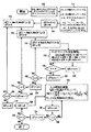
図6は、例えば、入力RGB値を、出力CMYK値にマップするために構成された(G−2)×(G−2)×(G−2)カラー・ルックアップ・テーブルから、バッファされたG×G×Gカラー・ルックアップ・テーブル(CLUT)を生成するため、及び、入力TRCsをスケーリングするための手順の実施例の概略フロー図を示す。オリジネーティング(originating)のCLUTは、アレイ又はテーブルL内に記憶される一方、バッファされたCLUTは、アレイ又はテーブルL’内に記憶される。オリジネーティング(originating)の入力TRCsは、入力アレイ又はテーブルTu’内にある一方、スケールされたTRCsは、入力アレイ又はテーブルTu内にある。オリジネーティングの及びスケールされたTRCsの各々は、t値を含む。
112において、各軸又は次元に沿った、オリジネーティングのCLUTの節点のナンバー(number)が、変数G’によって指定される。
FIG. 6 is buffered from, for example, a (G-2) × (G-2) × (G-2) color lookup table configured to map input RGB values to output CMYK values. FIG. 4 shows a schematic flow diagram of an embodiment of a procedure for generating a G × G × G color look-up table (CLUT) and scaling input TRCs. The originating CLUT is stored in the array or table L, while the buffered CLUT is stored in the array or table L ′. Originating input TRCs are in the input array or table Tu ′, while scaled TRCs are in the input array or table Tu. Each of the originating and scaled TRCs includes a t value.
At 112, the number of nodes in the originating CLUT along each axis or dimension is specified by the variable G ′.
113において、nが、オリジネーティングの、及びバッファされたCLUTsのための入力軸のナンバー(この実施例に対して、これは3である)に設定され、mが、出力軸(即ち、出力次元)のナンバーに設定され、オリジネーティングのCLUTが、(G’)3mのサイズの単一の次元的アレイL’として記憶される。アレイL’内の各要素(element)は、非負の(non-negative)スカラー値(scalar value)である。Tiは、i番めの軸のためのt値のオリジネーティングの入力TRCであり、各オリジネーティングのTRC値は、定数MAXより小さい、或いは、それと等しい、非負のスカラー値であり得る。
114において、Gが、バッファされたCLUTのための軸当りの節点のナンバーに設定され、バッファされたCLUTに対する第1のインデックス・カウンタiは、0に初期化される。バッファされたCLUTは、軸当り、余分の(extra)2つの節点を持つことになり、従って、G=G’+2である。
115において、式i’=Max(0,Min(G’−1,i−1))を用いて、i’の値がiから計算される。ここで、i’は、オリジネーティングのCLUTのための第1のインデックス・カウンタである。また、バッファされたCLUTに対する第2のインデックス・カウンタjは、0に初期化される。
116において、式j’=Max(0,Min(G’−1,j−1))を用いて、jからj’の値が、計算される。ここで、j’は、オリジネーティングのCLUTのための第2のインデックス・カウンタである。また、バッファされたCLUTに対する第3のインデックス・カウンタkは、0に初期化される。
117において、式j’=Max(0,Min(G’−1,j−1))を用いて、j’の値が、jから計算される。ここで、j’は、オリジネーティングのCLUTのための第2のインデックス・カウンタである。また、出力次元カウンタuは、0に初期化される。オリジネーティングの及びバッファされたCLUTsは、同じ出力次元を持ち、それ故、同じ出力次元カウンタを用いることになる。
At 113, n is set to the number of the input axis for the originating and buffered CLUTs (for this example, this is 3), and m is the output axis (ie, output). Dimension) and the originating CLUT is stored as a single dimensional array L ′ of size (G ′) 3 m. Each element in the array L ′ is a non-negative scalar value. Ti is the t-value originating input TRC for the i-th axis, and each originating TRC value can be a non-negative scalar value less than or equal to the constant MAX.
At 114, G is set to the number of nodes per axis for the buffered CLUT, and the first index counter i for the buffered CLUT is initialized to zero. The buffered CLUT will have two extra nodes per axis, so G = G ′ + 2.
At 115, the value of i ′ is calculated from i using the formula i ′ = Max (0, Min (G′−1, i−1)). Where i ′ is the first index counter for the originating CLUT. Also, the second index counter j for the buffered CLUT is initialized to zero.
At 116, the value from j to j ′ is calculated using the formula j ′ = Max (0, Min (G′−1, j−1)). Where j ′ is the second index counter for the originating CLUT. Also, the third index counter k for the buffered CLUT is initialized to zero.
At 117, the value of j ′ is calculated from j using the formula j ′ = Max (0, Min (G′−1, j−1)). Where j ′ is the second index counter for the originating CLUT. The output dimension counter u is initialized to 0. Originating and buffered CLUTs have the same output dimensions and therefore will use the same output dimension counter.
118において、バッファされたCLUT Lが設置される(populated)。オリジネーティングのCLUTの内側節点は、バッファされたCLUTに、一回だけ複製される一方、オリジネーティングのCLUTの外側表面の上の節点は、バッファされたCLUTに、複数回複製される。バッファされたCLUTアレイLは、(G)3mのサイズの単一の次元のアレイであり得る。アレイL及びL’は例えば、業界スタンダードのパッキング・オーダー(packing order)に従って、それぞれの、多次元ハッシュ関数a及びa’を通じてアクセスされ得る。
119において、出力次元カウンタuが1だけ増加される。
120において、uはmと比較される。これは、出力次元カウンタ・ループに対するフロー制御(flow control)である。もし、u<mならば、118において処理は継続する。さもなければ、処理は121に続く。
121において、第3のインデックス・カウンタkが1だけ増加される。
122において、kは、Gと比較される。これは、第3のインデックス・カウンタ・ループのためのフロー制御である。もし、k<Gならば、処理は、117において継続する。さもなければ、処理は、124において継続する。
124において、第2のインデックス・カウンタjが、1だけ増加される。
123において、jは、Gと比較される。これは、第2のインデックス・カウンタ・ループのためのフロー制御である。もしj<Gならば、処理は、116において継続する。さもなければ、処理は、125において継続する。
125において、第1のインデックス・カウンタiが、1だけ増加される。
126において、iはGと比較される。これは、第1のインデックス・カウンタ・ループのためのフロー制御である。もしi<Gならば、処理は、115において継続する。さもなければ、処理は、127において継続する。
127において、入力次元(dimension)カウンタuが0に初期化される。
128において、インデックス・カウンタiが0に初期化される。
At 118, the buffered CLUT L is populated. The inner node of the originating CLUT is replicated only once to the buffered CLUT, while the node on the outer surface of the originating CLUT is replicated multiple times to the buffered CLUT. The buffered CLUT array L may be a single dimensional array of size (G) 3 m. Arrays L and L ′ can be accessed through multi-dimensional hash functions a and a ′, respectively, for example, according to industry standard packing orders.
At 119, the output dimension counter u is incremented by one.
At 120, u is compared to m. This is a flow control for the output dimension counter loop. If u <m, processing continues at 118. Otherwise, processing continues at 121.
At 121, the third index counter k is incremented by one.
At 122, k is compared to G. This is the flow control for the third index counter loop. If k <G, processing continues at 117. Otherwise, processing continues at 124.
At 124, the second index counter j is incremented by one.
At 123, j is compared to G. This is the flow control for the second index counter loop. If j <G, processing continues at 116. Otherwise, processing continues at 125.
At 125, the first index counter i is incremented by one.
At 126, i is compared to G. This is the flow control for the first index counter loop. If i <G, processing continues at 115. Otherwise, processing continues at 127.
At 127, an input dimension counter u is initialized to zero.
At 128, the index counter i is initialized to zero.
130において、TRCsの入力範囲が調整される。T0T1T2は、新しい入力TRCsであり、そのそれぞれは、長さtの1次元アレイであり得る。スケールされた入力TRC値が、オリジネーティングの入力TRC値から計算され、Tuアレイに配置される。
131において、インデックス・カウンタiが、1だけ増加される。
132において、iは、tと比較される。これは、インデックス・カウンタ・ル−プのためのフロー制御である。もしi<tならば、処理は、130において継続する。さもなければ、処理は133において継続する。
133において、入力次元カウンタuが1だけ増加される。
129において、uはnと比較される。これは、入力次元カウンタ・ループのためのフロー制御である。もしu<nならば、処理は、128において継続する。さもなければ、処理は、終了する。
元々提示され、そして、後に補正され得る請求項は、現在予測できない又は理解できないものを含み、例えば、出願人/特許権者及び他の者から産まれ得る、ここに開示された実施例及び教示の、変形、代替物、修正、改善、均等物、及び、実質的均等物、を包含する。
At 130, the input range of TRCs is adjusted. T 0 T 1 T 2 are new input TRCs, each of which can be a one-dimensional array of length t. The scaled input TRC value is calculated from the originating input TRC value and placed in the Tu array.
At 131, the index counter i is incremented by one.
At 132, i is compared to t. This is the flow control for the index counter loop. If i <t, processing continues at 130. Otherwise, processing continues at 133.
At 133, the input dimension counter u is incremented by one.
At 129, u is compared to n. This is the flow control for the input dimension counter loop. If u <n, processing continues at 128. Otherwise, the process ends.
Claims originally presented and later amendable, including those currently unpredictable or unintelligible, include, for example, the embodiments and teachings disclosed herein that may come from the applicant / patentee and others , Variations, alternatives, modifications, improvements, equivalents, and substantially equivalents.
Claims (5)
前記PCS値を使用して、3次元の各々の中で(0+INT−E0)から(MAX−INT+E1)の範囲を持つルックアップ・テーブル入力を生成するステップ、
前記ルックアップ・テーブル入力及び前記ルックアップ・テーブルを用いて、目的地の色空間値を生成するステップであって、前記ルックアップ・テーブルが、G×G×G節点を含み、(G−2)×(G−2)×(G−2)節点を持つ内側部分、及び、当該内側部分を囲む[G×G×G−(G−2)×(G−2)×(G−2)]節点を持つ外側部分、を含むものであり、当該外側部分の当該節点が、当該内側部分の、対応する最も外側の節点の複製を備えるものである、
ステップを含み、
INTが、前記ルックアップ・テーブルのグリッド間隔であり、E0とE1の各々が、INTより小さく、MAXが正の整数である方法。 A method of converting a profile connection space (PCS) value into a destination color space value,
Using the PCS value to generate a lookup table entry having a range of (0 + INT−E0) to (MAX−INT + E1) in each of the three dimensions;
Generating a destination color space value using the lookup table input and the lookup table, the lookup table including G × G × G nodes; ) × (G−2) × (G−2) inner portion having nodes and surrounding the inner portion [G × G × G− (G−2) × (G−2) × (G−2)] An outer portion having a node, the node of the outer portion comprising a copy of the corresponding outermost node of the inner portion,
Including steps,
A method wherein INT is the grid spacing of the lookup table, each of E0 and E1 is less than INT, and MAX is a positive integer.
前記ルックアップ・テーブル入力及びルックアップ・テーブルを用いて、目的地の色空間値を四面体的に(tetrahedrally)補間するステップを含み、
前記ルックアップ・テーブルが、G×G×G節点を含み、(G−2)×(G−2)×(G−2)節点を有する内側部分、及び、当該内側部分を囲む[G×G×G−(G−2)×(G−2)×(G−2)]節点を有する外側部分、を備え、
前記外側部分の前記節点が、前記内側部分の、対応付けられた最も外側の節点の複製を備える、
請求項1に記載の方法。 Using the lookup table input and the lookup table to generate a destination color space value;
Using the lookup table input and the lookup table to tetrahedrally interpolate a destination color space value;
The lookup table includes G × G × G nodes, an inner portion having (G-2) × (G-2) × (G-2) nodes, and surrounding the inner portion [G × G × G- (G-2) × (G-2) × (G-2)] an outer portion having nodes,
The node of the outer portion comprises a copy of the associated outermost node of the inner portion;
The method of claim 1.
前記PCS値を、3×3マトリックスで乗算して、変換されたPCS値を生成し、そして、
色調の(tonal)再製カーブに従って前記変換されたPCS値を調整して、前記ルックアップ・テーブル入力を生成する、
ステップを含む、請求項1に記載の方法。 Using the PCS value to generate a lookup table;
Multiplying the PCS value by a 3 × 3 matrix to produce a transformed PCS value; and
Adjusting the transformed PCS value according to a tonal reproduction curve to generate the lookup table entry;
The method of claim 1, comprising steps.
バッファされたカラー・ルックアップ・テーブルと対応付けられた入力範囲より小さく、前記内側部分と対応付けられた入力範囲より大きい、範囲を有する入力色調再製曲線(curves)、
を含む色装置プロファイル。 A buffered color lookup table with the outermost node outside the inner part, the outermost node replicating the node of the inner part closest to the outermost node; Color lookup table, and
An input tone reproduction curve having a range that is less than the input range associated with the buffered color lookup table and greater than the input range associated with the inner portion;
Including color device profile.
Applications Claiming Priority (1)
| Application Number | Priority Date | Filing Date | Title |
|---|---|---|---|
| US10/816,759 US7209145B2 (en) | 2004-04-02 | 2004-04-02 | Color device profile having a buffered look-up table |
Publications (1)
| Publication Number | Publication Date |
|---|---|
| JP2005295545A true JP2005295545A (en) | 2005-10-20 |
Family
ID=34939104
Family Applications (1)
| Application Number | Title | Priority Date | Filing Date |
|---|---|---|---|
| JP2005087483A Pending JP2005295545A (en) | 2004-04-02 | 2005-03-25 | Color device profile having buffered lookup table |
Country Status (4)
| Country | Link |
|---|---|
| US (1) | US7209145B2 (en) |
| EP (1) | EP1587304B1 (en) |
| JP (1) | JP2005295545A (en) |
| DE (1) | DE602005017965D1 (en) |
Families Citing this family (9)
| Publication number | Priority date | Publication date | Assignee | Title |
|---|---|---|---|---|
| US7864366B2 (en) * | 2007-09-11 | 2011-01-04 | Xerox Corporation | Method and system for improved space filling interpolation |
| US8199360B2 (en) * | 2008-05-27 | 2012-06-12 | Xerox Corporation | Cooperative neighbor printing system profile methods and systems |
| US8125687B2 (en) | 2008-10-06 | 2012-02-28 | Canon Kabushiki Kaisha | Target for color characterization of color printer |
| US20120057785A1 (en) * | 2010-09-07 | 2012-03-08 | Peter Morovic | Method and system to modify a color lookup table |
| US8870319B2 (en) | 2012-05-02 | 2014-10-28 | Xerox Corporation | System and method for printing with ink limiting |
| CN110519593B (en) | 2014-03-04 | 2021-08-31 | 微软技术许可有限责任公司 | Adaptive switching of color spaces, color sampling rates and/or bit depths |
| WO2015131330A1 (en) | 2014-03-04 | 2015-09-11 | Microsoft Technology Licensing, Llc | Encoding strategies for adaptive switching of color spaces, color sampling rates and/or bit depths |
| JP6367359B2 (en) * | 2014-03-27 | 2018-08-01 | マイクロソフト テクノロジー ライセンシング,エルエルシー | Quantization / scaling and inverse quantization / scaling adjustments when switching color spaces |
| CN105960802B (en) | 2014-10-08 | 2018-02-06 | 微软技术许可有限责任公司 | Adjustment when switching color space to coding and decoding |
Citations (5)
| Publication number | Priority date | Publication date | Assignee | Title |
|---|---|---|---|---|
| JPH10117292A (en) * | 1996-08-02 | 1998-05-06 | Hewlett Packard Co <Hp> | Device for generating input data to interpolation device |
| JP2001257899A (en) * | 2000-03-09 | 2001-09-21 | Minolta Co Ltd | Color converter |
| JP2002344763A (en) * | 2001-03-15 | 2002-11-29 | Seiko Epson Corp | Image processing device |
| JP2004038693A (en) * | 2002-07-04 | 2004-02-05 | Canon Inc | Data conversion method and image processing device |
| JP2004072397A (en) * | 2002-08-06 | 2004-03-04 | Canon Inc | Image processing apparatus and image processing method |
Family Cites Families (8)
| Publication number | Priority date | Publication date | Assignee | Title |
|---|---|---|---|---|
| US5963201A (en) * | 1992-05-11 | 1999-10-05 | Apple Computer, Inc. | Color processing system |
| EP0715754A1 (en) * | 1994-07-01 | 1996-06-12 | Apple Computer, Inc. | Method and system for embedding a device profile into a document and extracting a device profile from a document in a color management system |
| US5881209A (en) * | 1994-09-13 | 1999-03-09 | Apple Computer, Inc. | Method and system for automatically generating printer profiles |
| US5646752A (en) | 1995-09-15 | 1997-07-08 | Canon Information Systems, Inc. | Color image processing apparatus which uses private tags to alter a predefined color transformation sequence of a device profile |
| US6008907A (en) | 1997-10-15 | 1999-12-28 | Polaroid Corporation | Printer calibration |
| US6466333B2 (en) | 1998-06-26 | 2002-10-15 | Canon Kabushiki Kaisha | Streamlined tetrahedral interpolation |
| US6690489B1 (en) | 1999-12-02 | 2004-02-10 | Hewlett-Packard Development Company, L.P. | Color conversion acceleration using lookup tables |
| US7253923B2 (en) * | 2001-03-15 | 2007-08-07 | Seiko Epson Corporation | Image processing apparatus |
-
2004
- 2004-04-02 US US10/816,759 patent/US7209145B2/en not_active Expired - Lifetime
-
2005
- 2005-03-25 JP JP2005087483A patent/JP2005295545A/en active Pending
- 2005-04-01 EP EP05102585A patent/EP1587304B1/en not_active Ceased
- 2005-04-01 DE DE602005017965T patent/DE602005017965D1/en not_active Expired - Lifetime
Patent Citations (5)
| Publication number | Priority date | Publication date | Assignee | Title |
|---|---|---|---|---|
| JPH10117292A (en) * | 1996-08-02 | 1998-05-06 | Hewlett Packard Co <Hp> | Device for generating input data to interpolation device |
| JP2001257899A (en) * | 2000-03-09 | 2001-09-21 | Minolta Co Ltd | Color converter |
| JP2002344763A (en) * | 2001-03-15 | 2002-11-29 | Seiko Epson Corp | Image processing device |
| JP2004038693A (en) * | 2002-07-04 | 2004-02-05 | Canon Inc | Data conversion method and image processing device |
| JP2004072397A (en) * | 2002-08-06 | 2004-03-04 | Canon Inc | Image processing apparatus and image processing method |
Also Published As
| Publication number | Publication date |
|---|---|
| EP1587304A3 (en) | 2008-01-23 |
| DE602005017965D1 (en) | 2010-01-14 |
| US7209145B2 (en) | 2007-04-24 |
| US20050219562A1 (en) | 2005-10-06 |
| EP1587304A2 (en) | 2005-10-19 |
| EP1587304B1 (en) | 2009-12-02 |
Similar Documents
| Publication | Publication Date | Title |
|---|---|---|
| US5583666A (en) | Method for cross-device color calibration and enhancement using explicit constraints | |
| JP2009505575A (en) | Hardware-accelerated color data processing | |
| KR101416222B1 (en) | How to create a gamut boundary descriptor that preserves discontinuity of the actual gamut surface | |
| JP2005295545A (en) | Color device profile having buffered lookup table | |
| JP3976849B2 (en) | Device for generating interpolator input data | |
| JP2008048432A (en) | Image processing apparatus | |
| JP2002304621A (en) | High-speed interpolation of large color look-up table | |
| JPH05181962A (en) | Method and apparatus for changing digital image size | |
| JP4804044B2 (en) | Image processing apparatus and image processing method | |
| JP4250493B2 (en) | Color conversion matrix generation method, color conversion table creation method and program | |
| US6628828B1 (en) | System and method for performing a recoloring operation sequence on color objects | |
| CN114529617B (en) | Image local color adjustment method and device, electronic equipment and storage medium | |
| JPH10117291A (en) | Decision device for input data path of interpolator | |
| JP3705316B2 (en) | Printing control apparatus, printing control method, and recording medium | |
| JP2004172809A (en) | Color management system | |
| JP4250466B2 (en) | Image processing apparatus, image processing method, recording medium thereof, and program | |
| JP2005176200A (en) | Color signal converting apparatus and method | |
| JP7532087B2 (en) | Apparatus, method, and program | |
| JP5997480B2 (en) | Image processing apparatus, image processing method, and program | |
| Zeng | Color accuracy in ICC color management system | |
| JP2010258758A (en) | Color conversion device and color conversion program | |
| KR0120562B1 (en) | How to create lookup table | |
| Tastl et al. | An efficient high quality color transformation | |
| CN101331774B (en) | System and method for applying curve effects to digital images | |
| JP2005167503A (en) | Image processing apparatus and image forming apparatus having the same |
Legal Events
| Date | Code | Title | Description |
|---|---|---|---|
| A621 | Written request for application examination |
Free format text: JAPANESE INTERMEDIATE CODE: A621 Effective date: 20080321 |
|
| A131 | Notification of reasons for refusal |
Free format text: JAPANESE INTERMEDIATE CODE: A131 Effective date: 20090928 |
|
| A521 | Request for written amendment filed |
Free format text: JAPANESE INTERMEDIATE CODE: A523 Effective date: 20091225 |
|
| A02 | Decision of refusal |
Free format text: JAPANESE INTERMEDIATE CODE: A02 Effective date: 20100412 |