JP2005295524A - Packet output-controlling device, packet shaper, and packet repeater - Google Patents
Packet output-controlling device, packet shaper, and packet repeater Download PDFInfo
- Publication number
- JP2005295524A JP2005295524A JP2005064971A JP2005064971A JP2005295524A JP 2005295524 A JP2005295524 A JP 2005295524A JP 2005064971 A JP2005064971 A JP 2005064971A JP 2005064971 A JP2005064971 A JP 2005064971A JP 2005295524 A JP2005295524 A JP 2005295524A
- Authority
- JP
- Japan
- Prior art keywords
- packet
- queue
- flow
- output control
- output
- Prior art date
- Legal status (The legal status is an assumption and is not a legal conclusion. Google has not performed a legal analysis and makes no representation as to the accuracy of the status listed.)
- Pending
Links
Images


Classifications
-
- Y02B60/45—
Abstract
Description
本発明は、QoS(Quality of Service:サービス品質)を保証するパケット伝送に使用されるパケット出力制御装置(例えば、パケットシェーパやスケジューラなど)及びそれを備えるパケット中継装置に関するものである。 The present invention relates to a packet output control device (for example, a packet shaper or a scheduler) used for packet transmission for guaranteeing QoS (Quality of Service) and a packet relay device including the same.
パケットシェーパは、入力部からパケットを入力し出力部からパケットを出力する。ここで、入力部の送信レートは、出力部の送信レートよりも大きい。したがって、入力部からパケットシェーパに入力されたパケットは、常に出力部から出力されるわけではなく、一定の場合、パケットシェーパにより廃棄されてしまう。 The packet shaper inputs a packet from the input unit and outputs a packet from the output unit. Here, the transmission rate of the input unit is larger than the transmission rate of the output unit. Therefore, a packet input from the input unit to the packet shaper is not always output from the output unit, and is discarded by the packet shaper in a certain case.
パケットにより通信されるデータの種類は様々である。例えば、web上のホームページの文字データをブラウズしたり、ftpによりサーバ上のファイルをダウンロードするだけならば、パケットの廃棄が発生しても実害は少ない。 There are various types of data communicated by packets. For example, if only browsing character data on a web page on a web or downloading a file on a server by ftp, even if a packet is discarded, there is little actual harm.
しかしながら、AV(Audio/Visual)通信に使用されるAVパケットには、リアルタイム性が要求される。即ち、AVパケットが廃棄され、所定の送信レートを確保できない場合には、画質や音質が劣化してしまい、好ましくない。したがって、AVパケットがパケットシェーパ等のパケット出力制御装置により廃棄されないための工夫が必要となる。 However, AV packets used for AV (Audio / Visual) communication are required to have real-time properties. That is, when the AV packet is discarded and a predetermined transmission rate cannot be secured, the image quality and the sound quality deteriorate, which is not preferable. Therefore, it is necessary to devise a way to prevent the AV packet from being discarded by a packet output control device such as a packet shaper.
さて、AV通信のためのプロトコルとしては、UDP等が適当であると考えられる。しかしながら、最近、コネクション型のプロトコル(例えば、TCP)の使用が検討されている。 Now, UDP or the like is considered appropriate as a protocol for AV communication. However, recently, the use of a connection-type protocol (for example, TCP) has been studied.
TCPは、輻輳制御機能をサポートする。具体的には、TCPによる通信では、送信データに関するAckパケットを監視する。そして、Ackパケットが全く到着しない場合や、Ackパケットが到着するまで長時間を要する場合には、輻輳が発生しているものと判定され、パケットの送信装置における輻輳制御機能が働き、パケットの送信レートが自動的に抑制される。この現象に対して、パケット出力制御装置は、直接的に関与できない。 TCP supports a congestion control function. Specifically, in TCP communication, an Ack packet related to transmission data is monitored. If no Ack packet arrives, or if it takes a long time until the Ack packet arrives, it is determined that congestion has occurred, and the congestion control function in the packet transmission device works to transmit the packet. The rate is automatically suppressed. The packet output control apparatus cannot directly participate in this phenomenon.
この現象は、パケットがAVパケットである場合にも、同様に発生する。その結果、送信レートが低下し、画質や音質が劣化してしまう。パケットシェーパにおいて、Ackパケット到着の遅延を引き起こす要素としては、キュー及びその制御技術が考えられる。
そこで本発明は、コネクション型プロトコルが使用される場合において、パケットの廃棄を極力抑制し、通信品質を維持しやすいパケット出力制御装置及びその関連技術を提供することを目的とする。 Accordingly, an object of the present invention is to provide a packet output control apparatus and related technology that can easily suppress communication discarding and maintain communication quality when a connection-type protocol is used.
第1の発明に係るパケット出力制御装置は、それぞれがパケットを蓄積する複数のキューと、複数のキューからのパケット出力を制御する出力制御部と、フロー毎に設定される廃棄パラメータを保持するフロー管理部と、フロー管理部の廃棄パラメータを参照し、廃棄条件が満たされない限り、入力されたパケットを、複数のキューのいずれかに挿入するキュー管理部とを備え、廃棄条件は、複数のキューの合計キュー長に基づいて定められる。 A packet output control device according to a first aspect of the present invention includes a plurality of queues each storing packets, an output control unit that controls packet output from the plurality of queues, and a flow that holds discard parameters set for each flow. A management unit and a queue management unit that refers to the discard parameter of the flow management unit and inserts an input packet into one of a plurality of queues as long as the discard condition is not satisfied. Is determined based on the total queue length.
第2の発明に係るパケット出力制御装置では、出力制御部は、複数のキューのいずれかから出力されるパケットのレートを設定するレート設定制御部を有する。 In the packet output control apparatus according to the second aspect of the present invention, the output control unit includes a rate setting control unit that sets a rate of packets output from any of the plurality of queues.
これらの構成において、廃棄条件を、複数のキューの合計キュー長に基づいて定めているため、パケットの物理的廃棄が発生していない状態において、コネクション型のパケットは遅延無く伝送される。したがって、実際にはパケットの物理的廃棄が発生していないにもかかわらず、コネクション型のプロトコルの機能により、勝手にパケットの送信レートが下げられてしまうという事態を回避できる。その結果、コネクション型のプロトコルによるAV通信においても、画質や音質の劣化を抑制できる。 In these configurations, since the discard condition is determined based on the total queue length of a plurality of queues, the connection-type packet is transmitted without delay in a state where the packet is not physically discarded. Therefore, it is possible to avoid a situation in which the packet transmission rate is arbitrarily lowered by the function of the connection-type protocol even though the packet is not physically discarded. As a result, deterioration in image quality and sound quality can be suppressed even in AV communication using a connection-type protocol.
第3の発明に係るパケット出力制御装置では、廃棄条件は、入力されたパケットのパケット長と、フロー管理部に保持された、このパケットに係るフローの廃棄パラメータに基づいて定められる。 In the packet output control apparatus according to the third invention, the discard condition is determined based on the packet length of the input packet and the discard parameter of the flow related to the packet held in the flow management unit.
この構成により、フローの優先度に差が付けられるため、相対的に有利になるフローに属するパケットは、廃棄を免れることになり、このフローの通信品質は維持される。その結果、複数の高優先度のフローがあり、高優先度のパケットの総計が、出力インターフェイスの帯域を超えてしまう場合でも、全てのフローの通信品質が、同時に劣化する事態を回避できる。 With this configuration, since the priority of the flow is differentiated, packets belonging to a relatively advantageous flow are prevented from being discarded, and the communication quality of this flow is maintained. As a result, even when there are a plurality of high-priority flows and the total of high-priority packets exceeds the bandwidth of the output interface, it is possible to avoid a situation in which the communication quality of all the flows deteriorates at the same time.
第4の発明に係るパケット出力制御装置では、複数のキューは、プロトコル別に用意される。 In the packet output control apparatus according to the fourth invention, a plurality of queues are prepared for each protocol.
この構成により、プロトコルの特性に合わせて、パケットの優先制御を行える。 With this configuration, priority control of packets can be performed in accordance with protocol characteristics.
第5の発明に係るパケット出力制御装置では、プロトコルには、TCPが含まれる。 In the packet output control apparatus according to the fifth invention, the protocol includes TCP.
この構成により、コネクション型のプロトコルの代表例である、TCPに対応できる。 With this configuration, it is possible to cope with TCP, which is a typical example of a connection type protocol.
第6の発明に係るパケット出力制御装置では、廃棄条件は、仮想パケットキューを用いて判定される。 In the packet output control apparatus according to the sixth aspect, the discard condition is determined using the virtual packet queue.
この構成において、仮想パケットキューを用いているため、廃棄条件の判定時に合計キュー長の演算を行う必要が無く、処理を高速化できる。 In this configuration, since the virtual packet queue is used, it is not necessary to calculate the total queue length when determining the discard condition, and the processing can be speeded up.
第7の発明に係るパケット出力制御装置では、廃棄条件は、パケットカウンタを用いて判定される。 In the packet output control apparatus according to the seventh aspect of the invention, the discard condition is determined using a packet counter.
この構成において、パケットカウンタを用いているため、廃棄条件の判定時に合計キュー長の演算を行う必要が無く、処理を高速化できる。 In this configuration, since the packet counter is used, it is not necessary to calculate the total queue length when determining the discard condition, and the processing can be speeded up.
第8の発明に係るパケット出力制御装置では、レート設定制御部は、複数のキューのうちTCPプロトコル用に用意されたキューにパケットがある場合は、そのパケットを出力し、TCPプロトコル用に用意されたキューにパケットがない場合は、TCPプロトコル用に用意されたキューでないキューのパケットを出力する。 In the packet output control device according to the eighth aspect of the invention, the rate setting control unit outputs the packet when the queue is prepared for the TCP protocol among the plurality of queues, and is prepared for the TCP protocol. If there is no packet in the queue, a packet in a queue other than the queue prepared for the TCP protocol is output.
この構成により、プロトコルの機能により送信レートを下げられやすいTCPパケットを、UDPパケットよりも優先的に伝送でき、TCPパケットによるAV通信の品質を高く保持できる。 With this configuration, a TCP packet whose transmission rate can be easily lowered by the protocol function can be preferentially transmitted over a UDP packet, and the quality of AV communication using the TCP packet can be maintained high.
第9の発明に係るパケット出力制御装置では、廃棄条件は、入力されたパケットのパケット長と、複数のキューの合計キュー長との和が、廃棄パラメータより大であるとき、このパケットを廃棄することを示す。 In the packet output control apparatus according to the ninth aspect, the discard condition is that when the sum of the packet length of the input packet and the total queue length of the plurality of queues is larger than the discard parameter, the packet is discarded. It shows that.
この構成により、単純な大小比較のみによって、フロー毎に適切な優先制御を実施できる。 With this configuration, appropriate priority control can be performed for each flow only by simple size comparison.
第10の発明に係るパケット出力制御装置では、キュー管理部は、複数のフローについて、共用される。 In the packet output control apparatus according to the tenth aspect, the queue management unit is shared for a plurality of flows.
この構成により、フローの管理を簡潔且つ容易に実施できる。 With this configuration, the flow management can be performed simply and easily.
第11の発明に係るパケット出力制御装置では、フロー管理部は、フローの通信開始時刻による先着順に従い、より早く通信が開始されたフローが有利になるように、廃棄パラメータを設定する。 In the packet output control apparatus according to the eleventh aspect, the flow management unit sets the discard parameter so that the flow whose communication is started earlier is advantageous in accordance with the first-come-first-served basis according to the communication start time of the flow.
この構成により、通信開始時刻が早いフローは、有利に扱われることになり、新参のフローにより、古参のフローの品質が劣化することがなく、合理的な通信制御を行える。 With this configuration, a flow with an early communication start time is treated favorably, and the quality of an old flow is not deteriorated by a new flow, and rational communication control can be performed.
本発明によれば、(入力インターフェイスのレートの総和)が(出力インターフェイスのレート)を上回る状況にあるパケット中継装置において、次の効果がある。 Advantageous Effects of Invention According to the present invention, the following effects can be achieved in a packet relay device in which (sum of input interface rates) exceeds (output interface rate).
複数の映像フローがあり、高優先のパケットの総計が出力インターフェイスのレートを超えてしまう場合、全映像の画質が同時に劣化することを防止でき、かつ、事前のシグナリングを必要とせず、システム全体としてのコストを抑制できる。さらに、TCPパケットのキュー遅延を可能な限り低減できるので、TCPを用いた映像フローでもキュー遅延によるレート低下がもたらす映像品質劣化を防ぐことができる。さらに、ADSLや無線やVPNにおいて、利用可能な通信レートを最大限に利用しながら、複数の映像サービスを提供できる。 If there are multiple video flows and the total number of high-priority packets exceeds the output interface rate, the image quality of all videos can be prevented from degrading at the same time, and no prior signaling is required. Can reduce costs. Furthermore, since the queue delay of the TCP packet can be reduced as much as possible, it is possible to prevent the video quality deterioration caused by the rate reduction due to the queue delay even in the video flow using TCP. Furthermore, a plurality of video services can be provided while making maximum use of available communication rates in ADSL, wireless, and VPN.
特に、本発明は、複数のキューの合計長に基づく制御を実施しているため、TCPのようなコネクション型のプロトコルを使用したAV通信において、画質や音質の劣化を抑制できる。 Particularly, since the present invention performs control based on the total length of a plurality of queues, it is possible to suppress deterioration in image quality and sound quality in AV communication using a connection-type protocol such as TCP.
以下、図面を参照しながら、本発明の実施の形態を説明する。 Hereinafter, embodiments of the present invention will be described with reference to the drawings.
(実施の形態1)
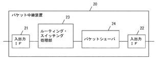
図1に示すように、このパケット中継装置20は、次の要素を有する。まず、2つの入出力インターフェイス21、22は、パケットの入出力を行う。
(Embodiment 1)
As shown in FIG. 1, the
ルーティング・スイッチング処理部23は、これらの入出力インターフェイス21、22のうち、一の入出力インターフェイス21から他の入出力インターフェイス22へ、パケットを転送する。
The routing /
パケットシェーパ24は、ルーティング・スイッチング処理部23と、他の入出力インターフェイス22との間に介装され、ルーティング・スイッチング処理部23が出力するパケットを、シェーピングして、他の入出力インターフェイス22へ出力する。
The
パケット中継装置20あるいはパケットシェーパ24は、いずれも、複数の筐体に実装される単独の装置の組み合わせ、1つの筐体に実装される単独の装置、1つの筐体内に装着される基板上の回路、1つの基板上に実装される単体の集積回路の全部又は一部のうち、いずれの形態においても構成できる。このような形態のうちのいずれをとるかにかかわらず、本発明の骨子を採用したパケット中継装置20あるいはパケットシェーパ24は、本発明に包含される。
Each of the
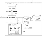
また、このパケットシェーパ24は、図2に示すように、次の要素を有する。まず、TCPパケットキュー245は、一定のキュー長を持ち、TCPパケットを一時蓄積する。UDPパケットキュー246も同様に一定のキュー長を持ち、UDPパケットを一時蓄積する。これらのキュー245、246は、プロトコル別に用意される複数のキューに相当する。
Further, the
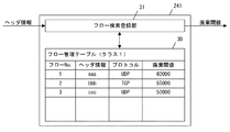
フロー管理部241は、フロー毎に設定される廃棄パラメータを保持する。図3に示すように、フロー管理部241は、フロー管理テーブル30と、このテーブル30から所定のデータを検索したり、このテーブル30に所定のデータを登録したりする、フロー検索登録部31とを有する。このテーブル30は、各フローについて共用されており、フロー毎に廃棄閾値を、保持する。
The
ここで、フローは、例えば、送信元IPアドレス、送信元ポート番号、送信先IPアドレス、送信先ポート番号及びプロトコルを等しくするパケットの集合として定義される。 Here, a flow is defined as, for example, a set of packets that equalize a source IP address, a source port number, a destination IP address, a destination port number, and a protocol.
また、本形態では、これらのテーブルは、フローNo.、ヘッダ情報、廃棄閾値の、3つのフィールドを持ち、フロー毎にデータを管理する。 Further, in this embodiment, these tables are flow Nos. , Header information, discard threshold, and manages data for each flow.
この廃棄閾値は、廃棄パラメータに相当する値である。廃棄パラメータとしては、他に、キュー長に乗ずる係数などが考えられる。 This discard threshold is a value corresponding to the discard parameter. As the discard parameter, a coefficient to be multiplied by the queue length can be considered.
図2に示すように、フロー管理部241は、キュー管理部242から入力したパケットのヘッダ情報(フロー情報に相当)を入力する。
As shown in FIG. 2, the
すると、フロー検索登録部31がフロー管理テーブル30の検索を行い、そのヘッダ情報に対応するフローがフロー管理テーブル30にあれば、このヘッダ情報に対応するフローの、廃棄閾値を、キュー管理部242へ出力し、フロー管理テーブル30になければ、新たにヘッダ情報をフロー管理テーブル30に登録した上で、廃棄閾値をキュー管理部242へ出力する。
Then, the flow
キュー管理部242は、パケットを入力して、フロー管理部241の廃棄パラメータを参照し、このパケットに係る廃棄条件が満たされない限り、TPCパケットを、TCPパケットキュー245に、UDPパケットをUDPパケットキュー246に挿入する。この廃棄条件は、パケットのパケット長と、TCPパケットキュー245とUDPパケットキュー246の合計キュー長と、このパケットに係るフローの廃棄パラメータとに基づいて定められる。
The
スケジューラ247は、PQ(Priority Queuing)方式にしたがい、TCPパケットをUDPパケットよりも優先して出力する。即ち、スケジューラ247は、TCPパケットキュー245にパケットがある場合はTCPパケットキュー245から、TCPパケットキュー245にパケットがない場合はUDPパケットキュー246から、パケットをレート設定制御部244へ出力する。レート設定制御部244は、スケジューラ247から出力されるパケットの送信レートを設定し、設定された送信レートとなるように、スケジューラ247から入力したパケットを外部へ出力する。
The
実施の形態1では、キュー管理部242は、仮想パケットキュー248を用いてTCPパケットキュー245のキュー長とUDPパケットキュー246のキュー長との合計キュー長を管理する。なお、仮想パケットキュー248は、この合計キュー長の現在値を保持する機能を有するものであって、仮想パケットキュー248にパケットが実際に挿入されるわけではない。
In the first embodiment, the
キュー管理部242がパケットをTCPパケットキュー245又はUDPパケットキュー246のいずれかに挿入する際、キュー管理部242は、仮想パケットキュー248が保持する合計キュー長を、挿入されるパケット長だけ加算する。また、スケジューラ247がTCPパケットキュー245又はUDPパケットキュー246のいずれかからパケットをレート設定制御部244へ出力する際、スケジューラ247は、仮想パケットキュー248が保持する合計キュー長を、出力されるパケット長だけ減算する。このような加減算が実行されることにより、仮想パケットキュー248の合計キュー長は、TCPパケットキュー245の合計キュー長とUDPパケットキュー246のキュー長との合計キュー長を常に示す。
When the
キュー管理部242は、仮想パケットキュー248が保持する合計キュー長と、フロー管理部241から受け取った廃棄閾値とを用いて、次の廃棄条件により、パケットを2つのパケットキュー245、246のいずれかに挿入するか、あるいは、廃棄するかの判定を行う。
The
すなわち、(現在の合計キュー長+パケット長)>廃棄閾値の場合は該パケットを廃棄し、(現在の合計キュー長+パケット長)≦廃棄閾値の場合は、該パケットを該当するパケットキューに挿入する。 That is, if (current total queue length + packet length)> discard threshold, the packet is discarded, and if (current total queue length + packet length) ≦ discard threshold, the packet is inserted into the corresponding packet queue. To do.
また、フロー管理部241は、図3に例示しているように、早く開始されたフローから順に大きな廃棄閾値を付与する。
Further, as illustrated in FIG. 3, the
例えば、フローX、フローY、フローZの順で、3つのフローの通信が、開始された場合、フロー管理部241では、これらのフローに対する廃棄閾値Tx、Ty、TzがTx>Ty>Tzになるように値を割り当てある。
For example, when communication of three flows is started in the order of flow X, flow Y, and flow Z, the
因みに、図3の例では、フローNo.1が最も先に通信を開始しており、以下、フローNo.2、フローNo.3の順になっている。 Incidentally, in the example of FIG. No. 1 has started communication first. 2, Flow No. The order is 3.
このため、この順で、廃棄閾値が、「60000」、「55000」、「50000」というように、順に小さくなっている。 For this reason, in this order, the discard thresholds become smaller in order, such as “60000”, “55000”, and “50000”.
また、フロー管理部241は、一定時間以上パケットが到着しないフローに関しては、フロー管理テーブル30からそのエントリを削除する。
In addition, the
こうすることにより、先に始まったフローほど廃棄されにくくなり、先に始まったフローから優先的にキューに挿入され、パケットキューから出力される。 By doing this, the flow that started first is less likely to be discarded, and the flow that started first is preferentially inserted into the queue and output from the packet queue.
これにより、出力インターフェイス22のレートが入力インターフェイス21のレートよりも大きい場合に、出力インターフェイス22において輻輳が発生した場合でも、先に始まったフローで、かつ、出力インターフェイス22のレート内に収まっているフローのパケットに関しては、優先的に2つのキュー245、246のいずれかに挿入され、出力インターフェイス22のレートでシェーピングされて出て行くので、パケットの廃棄が発生しない。さらにTCPパケットキュー245とUDPパケットキュー246に分けて蓄積し、TCPパケットキュー245にパケットがある場合は、TCPパケットから優先的に出力されるので、TCPのキュー遅延によるレート低下を抑制することができる。
As a result, when the rate of the
これにより、TCPによるAV通信とUDPによるAV通信とが混在する場合でも、事前の予約をすることなく、輻輳時の全フローにわたるパケット廃棄を防止でき、映像通信の場合での全映像の同時劣化を抑制できる。 Thus, even when TCP AV communication and UDP AV communication coexist, it is possible to prevent packet discarding over all flows during congestion without making a reservation in advance, and simultaneous deterioration of all images in the case of video communication Can be suppressed.
また、フロー管理部241は、一定時間以上通信が継続しているフローの廃棄パラメータを、このフローが不利になるように変更し、累積使用量が一定量を超えたフローの廃棄パラメータを、このフローが不利になるように変更する。
In addition, the
これにより、特定のフローによって、帯域が独占されないようにし、帯域利用の公平性を担保できる。 Thereby, it is possible to prevent the bandwidth from being monopolized by a specific flow and to ensure the fairness of the bandwidth usage.
次に、図2において、仮に、仮想パケットキュー248、TCPパケットキュー245、UDPパケットキュー246及びスケジューラ247が存在せず、これらの代わりに、単一のキューが設けられ、その単一のキューにフロー1閾値、フロー2閾値及びフロー3閾値(大小関係は上記の通り)が設定される場合を考える。また、レート設定制御部244が設定するシェーピングレートが10Mbpsであり、TCPパケットからなる第1フロー(6Mbps)が先に流れ始め、次にUDPパケットからなる第2フロー(6Mbps)が流れ始めるものとする。さらに、フローは先着順で優先制御されるべき、つまり、第1フローが第2フローに優先されるべきものとする。
Next, in FIG. 2, the
(1)第1フローのみが流れる期間
このときの合計レートは、6Mbps(<シェーピングレート:10Mbps)であるから、単一のキューにパケットが溜まることはない。つまり、第1フローの表示品質は良好に保持される。
(1) Period during which only the first flow flows Since the total rate at this time is 6 Mbps (<shaping rate: 10 Mbps), packets do not accumulate in a single queue. That is, the display quality of the first flow is kept good.
(2)第1フローと第2フロートが流れる期間
第2フロー(UDP)が流れ始めると、合計レートは12Mbps(>シェーピングレート:10Mbps)となり、単一のキューのキュー長は増加し、フロー2閾値へ近づく。単一のキューのキュー長が増加すると、TCPパケットのAckパケットが送信装置へ返送される時間が長くなり、単一のキューのキュー長がフロー2閾値へ達する前に、TCPの輻輳制御機能が働いて第1フロー(TCP)のレートが自主的に下げられてしまうことがある。その結果、第1フロー(TCP)は、先着順では優先されるべきであるにもかかわらず、第1フロー(TCP)のTCPパケットにより構成されるAVデータの再生品質が劣化してしまう。
(2) Period in which the first flow and the second float flow When the second flow (UDP) starts to flow, the total rate becomes 12 Mbps (> shaping rate: 10 Mbps), the queue length of a single queue increases, and the
次に、以上の状態と同じ状態が、本形態によるパケット出力制御装置(パケットシェーパ)において発生する場合について説明する。 Next, a case where the same state as the above occurs in the packet output control device (packet shaper) according to the present embodiment will be described.
(1)第1フローのみが流れる期間
これは、上述と同様である。
(1) Period during which only the first flow flows This is the same as described above.
(2)第1フローと第2フロートが流れる期間
第2フロー(UDP)が流れ始めると、合計レートは12Mbps(>シェーピングレート:10Mbps)となり、仮想パケットキュー248の合計キュー長は増加する。しかしながら、TCPパケットキュー245とUDPパケットキュー246は、スケジューラ247によりスケジューリングされるから、UDPパケット246のキュー長のみが増加する。言い換えれば、TCPパケットキュー245のキュー長は、ほとんど変化しない。その結果、TCPの輻輳制御機能は働かず、TCPパケットにより構成されるAVデータの再生品質は良好に維持される。
(2) Period in which the first flow and the second float flow When the second flow (UDP) starts to flow, the total rate becomes 12 Mbps (> shaping rate: 10 Mbps), and the total queue length of the
反面、UDPパケットにより構成されるAVデータの再生品質が劣化することになるが、これは先着順の優先制御が正当に実施された結果に他ならないので、致し方ないことである。 On the other hand, the reproduction quality of AV data composed of UDP packets is deteriorated, but this is nothing but the result of the priority control in the first-come-first-served basis being properly implemented.
(実施の形態2)
図4は、本発明の実施の形態2におけるパケットシェーパのブロック図である。実施の形態2では、実施の形態1における仮想パケットキュー248に代えて、パケットカウンタ249を用いている。
(Embodiment 2)
FIG. 4 is a block diagram of a packet shaper according to
即ち、実施の形態2では、パケットカウンタ249がTCPパケットキュー245のキュー長とUDPパケットキュー246のキュー長との合計キュー長を保持する。但し、パケットカウンタ249のキュー長の取り扱いは、パケットカウンタ249の最小カウンタ値の単位で実施される。勿論、パケットカウンタ249は、この合計キュー長の現在値を保持する機能を有するものであって、パケットカウンタ249にパケットが実際に挿入されるわけではない。
That is, in the second embodiment, the
キュー管理部242がパケットをTCPパケットキュー245又はUDPパケットキュー246のいずれかに挿入する際、キュー管理部242は、パケットカウンタ249が保持する合計キュー長を、「1」だけ加算する。また、スケジューラ247がTCPパケットキュー245又はUDPパケットキュー246のいずれかからパケットをレート設定制御部244へ出力する際、スケジューラ247は、パケットカウンタ249が保持する合計キュー長を、「1」だけ減算する。
When the
このような加減算が実行されることにより、パケットカウンタ249の合計キュー長は、TCPパケットキュー245の合計キュー長とUDPパケットキュー246のキュー長との合計キュー長を常に示す。その他の点は、実施の形態1と同様である。
By performing such addition and subtraction, the total queue length of the
(実施の形態3)ADSLの場合
図5は、本発明の実施の形態3におけるパケット中継装置のブロック図である。実施の形態3は、実施の形態1または2をADSLに適用したものである。以下、実施の形態1または2と同様の内容については、説明を省略する。
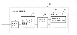
(Embodiment 3) ADSL FIG. 5 is a block diagram of a packet relay apparatus according to
さて、図5に示すように、本形態のパケット中継装置40は、他の入出力インターフェイス22の最大出力レートを計測するレート計測部41を有する。
Now, as shown in FIG. 5, the
そして、パケットシェーパ24のレート設定制御部244は、レート計測部41が計測した最大出力レートに基いて、動的にレートを変更するようになっている。ADSLの場合、宅内側の入出力インターフェイスは、100Mbpsであるが、ADSLの上りのレートは、高々500kbps程度であり、宅内から宅外への通信を行う場合、ADSLモデム50のところで輻輳が発生する。よって、パケットシェーパ24のレートを、500kbpsに設定すればよい。
The rate
こうすると、ADSLモデム50の付近での輻輳(無差別なパケット廃棄)は発生せず、実施の形態1で説明したように、500kbpsの範囲内におさまる映像の高優先フローに関しては、先着順で保護されるため、例えば、200kbpsの映像フローが3本以上あるような場合でも、最初に始まった2本のフローのパケット(400kbps分)は、優先的に保護され、3本目以降の映像フローのパケットが廃棄されるので、全映像が同時に劣化してしまうような事態を回避できる。
In this way, congestion (indiscriminate packet discard) does not occur in the vicinity of the
ここで、ADSLの通信可能レートは、局からユーザ宅までの距離に依存して、ユーザ毎に異なる。よって、実施の形態3では、レート計測部41を設け、設置後、その宅で利用できる通信可能レートを計測している。そして、計測した通信可能レートを、パケットシェーパ24のレート設定制御部244に設定している。
Here, the communicable rate of ADSL differs for each user depending on the distance from the station to the user's home. Therefore, in the third embodiment, the
これにより、ユーザ毎に異なるADSLの利用可能な通信レートを、最大限に有効利用しながら、輻輳時の全フローにわたるパケット廃棄を防止できるし、映像通信の場合、全映像が同時に劣化する事態を回避できる。 As a result, it is possible to prevent packet discarding over all flows during congestion while making maximum use of communication rates that can be used for different ADSLs for each user. Can be avoided.
ここで、レート計測部41による計測要領は、例えば次のように行えばよい。即ち、局側の通信装置に対し、ftpというファイル転送コマンドを用いて、ファイル転送を行い、その時の、転送時間より、通信レートを測定する。
Here, the measuring procedure by the
(実施の形態4)無線インターフェイス付きHGWの場合
図6は、本発明の実施の形態4におけるパケット中継装置のブロック図である。実施の形態4は、実施の形態1または2を無線インターフェイス付きホームゲートウエイ(HGW)に適用したものである。以下、実施の形態1または2と同様の内容については、説明を省略する。
(Embodiment 4) HGW with Radio Interface FIG. 6 is a block diagram of a packet relay device in Embodiment 4 of the present invention. In the fourth embodiment, the first or second embodiment is applied to a home gateway with a wireless interface (HGW). Hereinafter, description of the same contents as those in the first or second embodiment will be omitted.
図6に示すように、本形態のパケット中継装置60は、他の入出力インターフェイス(無線インターフェイス61)の最大出力レートを計測する、レート計測部としての、無線レートフィードバック部62を有する。
As shown in FIG. 6, the
そして、パケットシェーパ24のレート設定制御部244は、無線レートフィードバック部62が計測した最大出力レートに基いて、動的にレートを変更するようになっている。
Then, the rate
さて、図6に示す例において、有線の入出力インターフェイス21は、100Mbpsであるが、無線のインターフェイスは802.11aの場合、54Mbpsであり、宅内から宅外への通信を行う場合に、輻輳が発生しうる。
In the example shown in FIG. 6, the wired input /
よって、パケットシェーパ24のレートを、54Mbpsに設定するとよい。こうすると、無線インターフェイス61の付近での輻輳(無差別なパケット廃棄)は発生しない。
Therefore, the rate of the
また、実施の形態1で説明したように、54Mbpsの範囲内におさまる映像の高優先フローに関しては、先着順で保護されるので、例えば、6Mbpsの映像フローが10本以上あるような場合でも、最初に始まった9本のフローのパケット(54Mbps分)は、優先的に保護され、10本目以降の映像フローのパケットが廃棄されるため、全映像が同時に劣化する事態を回避できる。 In addition, as described in the first embodiment, the high priority flow of the video that falls within the range of 54 Mbps is protected on a first-come-first-served basis. For example, even when there are 10 or more 6 Mbps video flows, The first 9 packets of flow (for 54 Mbps) that are started first are protected preferentially, and the packets of the 10th and subsequent video flows are discarded, so that it is possible to avoid a situation in which all videos deteriorate simultaneously.
また、無線の場合は、相手端末の位置や障害物の有無により、通信可能なレートが変動する。例えば、802.11aにおいては、通信に失敗すると伝送レートを1段階ずつ下げてデータを再送する。 In the case of wireless communication, the communicable rate varies depending on the position of the counterpart terminal and the presence or absence of an obstacle. For example, in 802.11a, when communication fails, data is retransmitted with the transmission rate lowered by one step.
よって、本形態では、レート計測部として、無線レートフィードバック部62を設け、動的に変る現在の伝送レートを、パケットシェーパ24のレート設定制御部244に設定している。
Therefore, in this embodiment, the radio
これにより、無線のように、利用可能な通信レートが変動する場合も、変動する通信路の能力を最大限に有効利用しながら、輻輳時の全フローにわたるパケット廃棄を防止でき、映像通信の場合、全映像が同時に劣化する事態を回避できる。 As a result, even when the available communication rate fluctuates, such as wireless, packet discard over all flows during congestion can be prevented while maximizing effective use of the fluctuating channel capability. , It is possible to avoid a situation in which all the images deteriorate simultaneously.
(実施の形態5)VPNルータの場合
図7は、本発明の実施の形態5におけるパケット中継装置を用いたシステム図である。本形態は、実施の形態3または4に類似の構成をなす、パケット中継装置70、80であって、ネットワーク90を経由し、相対向して接続されるものに適用した例に関する。より具体的には、パケット中継装置70、80は、VPNルータとして使用される。
(Embodiment 5) VPN router FIG. 7 is a system diagram using a packet relay apparatus in
本形態のパケット中継装置70、80におけるレート計測部71、81は、通信相手のパケット中継装置80、70とパケットの送受信を行い、通信相手のパケット中継装置との間の最大レートを計測する。
The
さて、通常のVPNの場合、セキュリティは、暗号化等によって保証されるが、通信レートは、一般に保証されない。 In the case of a normal VPN, security is guaranteed by encryption or the like, but a communication rate is generally not guaranteed.
よって、本形態では、パケット中継装置70にレート計測部71を設け、対向のパケット中継装置80(VPNルータ)のレート計測部81と、レート計測用のパケットのやり取りを行い、その時のパケット転送レートにより、現在、利用できる通信可能レートを計測し、それぞれのパケットシェーパ24のレート設定制御部244に設定するようにした。
Therefore, in this embodiment, the
これにより、VPNで利用可能な通信レートを、最大限に有効利用しながら、輻輳時の全フローにわたるパケット廃棄を防止でき、映像通信の場合、全映像が同時に劣化する事態を回避できる。 As a result, it is possible to prevent packet discarding over all flows at the time of congestion while maximally effectively using the communication rate that can be used in the VPN, and in the case of video communication, it is possible to avoid a situation in which all videos deteriorate simultaneously.
(実施の形態6)
図8は、本発明の実施の形態6におけるパケット出力制御装置(スケジューラ)のブロック図である。本形態は、実施の形態1のスケジューラ版に相当する。図8に示すように、このパケット出力制御装置100は、図2のほとんどの構成要素を含むが、レート設定制御部244を含まない。
(Embodiment 6)
FIG. 8 is a block diagram of a packet output control device (scheduler) in Embodiment 6 of the present invention. This embodiment corresponds to the scheduler version of the first embodiment. As shown in FIG. 8, the packet
キュー管理部242の前段に、入力されたパケットを、クラス1パケット(優先対象:例えば、AVパケット等)とクラス2パケット(非優先対象:例えば、ベストエフォートパケット等)とに分類するクラシファイア101が設けられる。クラシファイア101により分類されたクラス1パケットは、キュー管理部242に入力され、その後、図2のレート設定制御部244の直前まで、実施の形態1と同様の処理を受け、出力スケジューラ103へ入力される。
A
また、クラス2パケットを蓄積するために、その他キュー102が設けられている。クラシファイア101により分類されたクラス2パケットは、その他キュー102に入力される。
In addition, another
出力スケジューラ103は、図2から追加された要素であり、所定の方式によりスケジューラ247又はその他キュー102からパケットを取り出して外部へ出力する。出力スケジューラ103のスケジュール方式は任意であるが、通常、出力スケジューラ103は、その他キュー102よりもスケジューラ247からのパケットを優先して外部へ出力する。
The
本形態のように、スケジューラ型のパケット出力制御装置100においても、TCPパケットキュー245からのパケット出力が滞ると、TCPがサポートする輻輳制御機能が働いて、TCPパケットの送信レートが自主的に下げられてしまい、TCPパケットにより構成されるAVデータの再生品質が劣化する点は、実施の形態1において述べたとおりである。
As in the present embodiment, even in the scheduler type packet
以上の説明から明らかなように、本発明は、スケジューラ型のパケット出力制御装置においても有用であり、シェーパ型のパケット出力制御装置と同等の効果が得られる。 As is apparent from the above description, the present invention is also useful in a scheduler type packet output control device, and the same effect as a shaper type packet output control device can be obtained.
本発明に係るパケットシェーパは、例えばAVパケットを中継するネットワーク等において好適に利用できる。 The packet shaper according to the present invention can be suitably used in, for example, a network that relays AV packets.
21、22 入出力インターフェイス
23 ルーティング・スイッチング処理部
24、40、60、70、80 パケットシェーパ
30 フロー管理テーブル
31 フロー検索登録部
41、71、81 レート計測部
50 ADSLモデム
61 無線インターフェイス
62 無線レートフィードバック部
90 ネットワーク
241 フロー管理部
242 キュー管理部
243 パケットキュー
244 レート設定制御部
245 TCPパケットキュー
246 UDPパケットキュー
248 仮想パケットキュー
249 パケットカウンタ
21, 22 Input /
Claims (18)
前記複数のキューからのパケット出力を制御する出力制御部と、
フロー毎に設定される廃棄パラメータを保持するフロー管理部と、
前記フロー管理部の廃棄パラメータを参照し、廃棄条件が満たされない限り、入力されたパケットを、前記複数のキューのいずれかに挿入するキュー管理部とを備え、
前記廃棄条件は、前記複数のキューの合計キュー長に基づいて定められる、パケット出力制御装置。 Multiple queues each storing packets,
An output control unit for controlling packet output from the plurality of queues;
A flow management unit that holds discard parameters set for each flow;
A queue management unit that refers to the discard parameter of the flow management unit and inserts an input packet into one of the plurality of queues unless a discard condition is satisfied;
The packet output control device, wherein the discard condition is determined based on a total queue length of the plurality of queues.
前記複数の入出力インターフェイスのうち、一の入出力インターフェイスから他の入出力インターフェイスへ、パケットを転送するルーティング・スイッチング処理部と、
前記ルーティング・スイッチング処理部と、他の入出力インターフェイスとの間に介装され、前記ルーティング・スイッチング処理部が出力するパケットを、シェーピングして、他の入出力インターフェイスへ出力するパケット出力制御装置とを備え、
前記パケット出力制御装置は、
それぞれがパケットを蓄積する複数のキューと、
前記複数のキューからのパケット出力を制御する出力制御部と、
フロー毎に設定される廃棄パラメータを保持するフロー管理部と、
前記フロー管理部の廃棄パラメータを参照し、廃棄条件が満たされない限り、入力されたパケットを、前記複数のキューのいずれかに挿入するキュー管理部とを備え、
前記廃棄条件は、前記複数のキューの合計キュー長に基づいて定められる、パケット出力制御装置。 Multiple input / output interfaces for packet input / output,
A routing / switching processor that transfers packets from one input / output interface to another input / output interface among the plurality of input / output interfaces;
A packet output control device that is interposed between the routing / switching processing unit and another input / output interface, shapes the packet output from the routing / switching processing unit, and outputs the packet to the other input / output interface; With
The packet output control device includes:
Multiple queues each storing packets,
An output control unit for controlling packet output from the plurality of queues;
A flow management unit that holds discard parameters set for each flow;
A queue management unit that refers to the discard parameter of the flow management unit and inserts an input packet into one of the plurality of queues unless a discard condition is satisfied;
The packet output control device, wherein the discard condition is determined based on a total queue length of the plurality of queues.
前記パケット出力制御装置の前記出力制御部は、前記複数のキューのいずれかから出力されるパケットのレートを設定するレート設定制御部を有し、
前記レート設定制御部は、前記レート計測部が計測した最大出力レートに基いて、動的にレートを変更する、請求項15記載のパケット中継装置。 With a rate measurement unit that measures the maximum output rate of other input / output interfaces,
The output control unit of the packet output control device has a rate setting control unit that sets a rate of packets output from any of the plurality of queues,
The packet relay device according to claim 15, wherein the rate setting control unit dynamically changes the rate based on the maximum output rate measured by the rate measuring unit.
Priority Applications (1)
| Application Number | Priority Date | Filing Date | Title |
|---|---|---|---|
| JP2005064971A JP2005295524A (en) | 2004-03-09 | 2005-03-09 | Packet output-controlling device, packet shaper, and packet repeater |
Applications Claiming Priority (2)
| Application Number | Priority Date | Filing Date | Title |
|---|---|---|---|
| JP2004065380 | 2004-03-09 | ||
| JP2005064971A JP2005295524A (en) | 2004-03-09 | 2005-03-09 | Packet output-controlling device, packet shaper, and packet repeater |
Publications (1)
| Publication Number | Publication Date |
|---|---|
| JP2005295524A true JP2005295524A (en) | 2005-10-20 |
Family
ID=35327901
Family Applications (1)
| Application Number | Title | Priority Date | Filing Date |
|---|---|---|---|
| JP2005064971A Pending JP2005295524A (en) | 2004-03-09 | 2005-03-09 | Packet output-controlling device, packet shaper, and packet repeater |
Country Status (1)
| Country | Link |
|---|---|
| JP (1) | JP2005295524A (en) |
Cited By (4)
| Publication number | Priority date | Publication date | Assignee | Title |
|---|---|---|---|---|
| JP2010213098A (en) * | 2009-03-11 | 2010-09-24 | Mitsubishi Electric Corp | Priority control apparatus and priority control method |
| JP2011151601A (en) * | 2010-01-21 | 2011-08-04 | Alaxala Networks Corp | Packet relay device and packet relay method |
| JP2017188870A (en) * | 2016-03-30 | 2017-10-12 | アラクサラネットワークス株式会社 | Communication device and communication method |
| US10326705B2 (en) | 2016-03-30 | 2019-06-18 | Alaxala Networks Corporation | Communication device and communication method |
-
2005
- 2005-03-09 JP JP2005064971A patent/JP2005295524A/en active Pending
Cited By (4)
| Publication number | Priority date | Publication date | Assignee | Title |
|---|---|---|---|---|
| JP2010213098A (en) * | 2009-03-11 | 2010-09-24 | Mitsubishi Electric Corp | Priority control apparatus and priority control method |
| JP2011151601A (en) * | 2010-01-21 | 2011-08-04 | Alaxala Networks Corp | Packet relay device and packet relay method |
| JP2017188870A (en) * | 2016-03-30 | 2017-10-12 | アラクサラネットワークス株式会社 | Communication device and communication method |
| US10326705B2 (en) | 2016-03-30 | 2019-06-18 | Alaxala Networks Corporation | Communication device and communication method |
Similar Documents
| Publication | Publication Date | Title |
|---|---|---|
| US20050201373A1 (en) | Packet output-controlling device, packet transmission apparatus | |
| US8917597B2 (en) | Providing a quality of service for various classes of service for transfer of electronic data packets | |
| US11316795B2 (en) | Network flow control method and network device | |
| US7948883B1 (en) | Applying router quality of service on a cable modem interface on a per-service-flow basis | |
| US7802008B2 (en) | Quality of service management in network gateways | |
| US7633869B1 (en) | Automatic network traffic characterization | |
| KR101508389B1 (en) | Communications Networks | |
| EP1553740A1 (en) | Method and system for providing committed information rate (CIR) based fair access policy | |
| US20040125815A1 (en) | Packet transmission apparatus and method thereof, traffic conditioner, priority control mechanism and packet shaper | |
| US20070223470A1 (en) | System and Method for Enhancing Network Quality of Service | |
| US11283721B2 (en) | Application-based traffic control in multipath networks | |
| JP2003348642A (en) | Wireless communication apparatus and wireless communication method | |
| WO2011000810A1 (en) | Method of managing a traffic load | |
| WO2020090474A1 (en) | Packet forwarding apparatus, method and program | |
| JPWO2009072247A1 (en) | Communication device | |
| JP2005295524A (en) | Packet output-controlling device, packet shaper, and packet repeater | |
| JP2014518047A (en) | Data packet loss reduction system and method using adaptive transmission queue length | |
| US20230142425A1 (en) | Virtual dual queue core stateless active queue management (agm) for communication networks | |
| JP2008205721A (en) | Data transfer device, base station and data transfer method | |
| JP2005117125A (en) | Packet transmission control apparatus | |
| JP4893216B2 (en) | Network management device, bandwidth control method, and program | |
| JP2004166080A (en) | Packet shaper and packet relaying device | |
| US20100214914A1 (en) | Method of bandwidth management in packet networks | |
| Joo et al. | RIO configuration optimization for assured service in diffserv networks | |
| Culverhouse et al. | Optimising Quality of Service through the controlled aggregation of traffic |