JP2005295421A - Image communication system, image pickup apparatus, image pickup control method, and image pickup control program - Google Patents
Image communication system, image pickup apparatus, image pickup control method, and image pickup control program Download PDFInfo
- Publication number
- JP2005295421A JP2005295421A JP2004110766A JP2004110766A JP2005295421A JP 2005295421 A JP2005295421 A JP 2005295421A JP 2004110766 A JP2004110766 A JP 2004110766A JP 2004110766 A JP2004110766 A JP 2004110766A JP 2005295421 A JP2005295421 A JP 2005295421A
- Authority
- JP
- Japan
- Prior art keywords
- image
- image information
- unit
- information
- imaging
- Prior art date
- Legal status (The legal status is an assumption and is not a legal conclusion. Google has not performed a legal analysis and makes no representation as to the accuracy of the status listed.)
- Pending
Links
Images


Landscapes
- Television Signal Processing For Recording (AREA)
- Facsimiles In General (AREA)
- Studio Devices (AREA)
Abstract
【課題】 自機が有する機能や性能を他のカメラのユーザに利用させたり、自機が有しない機能を他のカメラによって補完する等の、他機カメラの有効利用を可能にする。
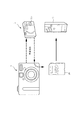
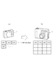
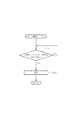
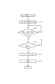
【解決手段】 このカメラシステムは共にデジタルカメラであって無線接続される親機Aと、子機Bとで構成されている。親機Aは、解像度、記憶容量等において子機Bよりも高機能で表示部も備えたデジタルカメラであり、子機Bは親機Aよりも低機能な表示部等を備えない簡易型のデジタルカメラである。そして、子機Bで撮影した画像を親機Aに送信して、親機Aのメモリカードに記憶させることにより、コンビニエンスストア等に配置されている印刷機Cで印刷可能としたり、子機Bで撮影した画像を親機A送信して、親機Aの表示部に表示させて視認可能にする。
【選択図】 図1PROBLEM TO BE SOLVED: To enable effective use of a camera of another device, for example, causing a user of another camera to use a function or performance possessed by the device, or supplementing a function not possessed by the device with another camera.
The camera system is composed of a master unit A and a slave unit B, both of which are digital cameras and are wirelessly connected. The master unit A is a digital camera that has higher functions than the slave unit B and has a display unit in terms of resolution, storage capacity, etc. It is a digital camera. Then, an image photographed by the slave unit B is transmitted to the master unit A and stored in the memory card of the master unit A so that printing can be performed by the printer C arranged in the convenience store or the like The image captured in step A is transmitted to the parent device A and displayed on the display unit of the parent device A so that the image can be viewed.
[Selection] Figure 1
Description
本発明は、第1の撮像装置と第2の撮像装置とで構成される画像通信システム、撮像装置、撮像制御方法、及び、撮像制御プログラムカメラシステムに関する。 The present invention relates to an image communication system composed of a first imaging device and a second imaging device, an imaging device, an imaging control method, and an imaging control program camera system.
今日においては、多種多様なデジタルカメラが出現するに至っている。例えば、上位機種においては、ズーム機能やAF機能を備えるとともに高解像度を有し、記憶容量の大きな内部メモリを有するのみならず外部記憶媒体を装着することも可能である。一方、低位機種にあっては、固定焦点であって内部メモリのみを有し、内部メモリにあってもその容量は比較的少ない。また、外部との通信機能を有し、撮像した画像データを外部のサーバに送信することが可能なデジタルカメラも出現するに至っている(例えば、特許文献1参照。)。
しかしながら、このように多種多様なデジタルカメラが出現するに至ってはいるものの、これらのデジタルカメラは自機が有する各種機能を自機においてのみ発現させることができるに過ぎない。したがって、自機が有する機能や性能を他のデジタルカメラに利用させたり、自機が有しない機能を他のデジタルカメラによって補完する等の、他のデジタルカメラの有効利用を図ることができるものではなった。 However, although a variety of digital cameras have emerged in this way, these digital cameras can only exhibit various functions of their own devices only in their own devices. Therefore, it is not possible to use other digital cameras effectively, such as making other digital cameras use the functions and performance of their own devices, or supplementing the functions that they do not have with other digital cameras. became.
本発明は、かかる従来の課題に鑑みてなされたものであり、自機が有する機能や性能を他のカメラのユーザに利用させたり、自機が有しない機能を他のカメラによって補完する等の、他機カメラの有効利用を可能にしたカメラシステムを提供することを目的とする。 The present invention has been made in view of such conventional problems, such as allowing the user of another camera to use the function and performance of the own apparatus, and supplementing the function that the own apparatus does not have with another camera. An object of the present invention is to provide a camera system that enables effective use of cameras of other devices.
前記課題を解決するために請求項1記載の発明にあっては、第1の撮像装置と第2の撮像装置とからなる画像通信システムであって、前記第1の撮像装置は、撮像された画像情報を前記第2の撮像装置に無線送信する画像情報送信手段を備え、前記第2の撮像装置は、前記第1の撮像装置から無線送信される画像情報を受信する画像情報受信手段と、この画像情報受信手段により受信された画像情報を記憶する第1の記憶手段と、当該装置で撮像された画像情報を記憶する第2の記憶手段と、前記第1の記憶手段に記憶された画像情報と前記第2の記憶手段に記憶された画像情報とを一覧表示する表示手段とを備える。
In order to solve the above-mentioned problem, the invention according to
したがって、第1の撮像装置が記憶手段や表示手段を具備しない簡易型の撮像装置であっても、第1の撮像装置で撮像した画像を第2の撮像装置側の記憶手段に記憶させたり、表示手段に表示させる等が可能となる。よって、記憶手段や表示手段を有していない簡易型の撮像装置であっても、この簡易型の第1の撮像装置で撮像した画像を第2の撮像装置の記憶手段を有効に利用して記憶し、かつ表示手段を有効に利用して視認することができる。 Therefore, even if the first imaging device is a simple imaging device that does not include storage means or display means, the image captured by the first imaging device can be stored in the storage means on the second imaging device side, It can be displayed on the display means. Therefore, even in a simple imaging device that does not have storage means or display means, an image captured by this simple first imaging device can be used effectively by using the storage means of the second imaging device. It can be memorized and visually recognized using the display means effectively.
また、請求項2記載の発明に係る画像通信システムにあっては、前記第2の撮像装置は、前記第1の撮像装置の制御情報を無線送信する制御情報送信手段を更に備え、前記第1の撮像装置は、前記第2の撮像装置から送信された制御情報を無線受信する制御情報受信手段と、この制御情報受信手段によって無線受信された制御情報に従い当該装置を制御する制御手段とを更に備える。したがって、第2の撮像装置から第1の撮像装置に制御情報を送信すると、第1の撮像装置はこれを受信して、この情報に基づき対応する各種制御を実行する。よって、第1の撮像装置が有する機能を第2の撮像装置側から制御することができる。 In the image communication system according to the second aspect of the present invention, the second imaging device further includes control information transmitting means for wirelessly transmitting control information of the first imaging device, The image pickup apparatus further includes control information receiving means for wirelessly receiving the control information transmitted from the second image pickup apparatus, and control means for controlling the apparatus in accordance with the control information wirelessly received by the control information receiving means. Prepare. Therefore, when the control information is transmitted from the second imaging device to the first imaging device, the first imaging device receives this and executes various controls corresponding to this information. Therefore, the function of the first imaging device can be controlled from the second imaging device side.
また、請求項3記載の発明に係る画像通信システムにあっては、前記第1の撮像装置は、発光手段を更に備え、前記制御情報とは、前記発光手段の発光タイミングを制御する情報である。したがって、第1の撮像装置の発光動作を第2の撮像装置側から制御できることから、夜間等において第2の撮像装置内蔵のフラッシュでは光量が足りないロングショットの撮影などに、被写体付近に第1の撮像装置を配置することにより、撮影に必要な光量を確保することができる In the image communication system according to the third aspect of the present invention, the first imaging device further includes a light emitting unit, and the control information is information for controlling a light emission timing of the light emitting unit. . Therefore, since the light emitting operation of the first image pickup device can be controlled from the second image pickup device side, the first image near the subject is used for shooting long shots where the amount of light is insufficient with the flash built in the second image pickup device at night or the like. The amount of light required for shooting can be secured by arranging the imaging device
また、請求項4記載の発明に係る画像通信システムにあっては、前記制御情報とは、前記第1の撮像装置における撮像を制御する情報である。したがって、被写体の周囲に間隔を置いて複数個の第1の撮像装置を配置し、第2の撮像装置での操作により各第1の撮像装置に撮像処理を実行させることにより、被写体を異なる角度から撮影した画像を一瞬にして撮像することができ、マルチアングルの同時撮影が可能となる。 In the image communication system according to the fourth aspect of the present invention, the control information is information for controlling imaging in the first imaging device. Therefore, by arranging a plurality of first imaging devices at intervals around the subject and causing each first imaging device to perform an imaging process by an operation on the second imaging device, the subjects are arranged at different angles. Thus, it is possible to take an image taken from the moment, and to simultaneously take a multi-angle.
また、請求項5記載の発明に係る画像通信システムにあっては、前記第1の撮像装置は、当該装置の状態を示す状態情報を前記第2の撮像装置へ無線送信する状態情報送信手段を更に備え、前記第2の撮像装置は、前記第2の撮像装置から送信された状態情報を無線受信する状態情報受信手段と、この状態情報受信手段によって受信された前記第1の撮像装置の状態を、前記表示手段に表示するよう制御する表示制御手段とを更に備える。 In the image communication system according to the fifth aspect of the invention, the first imaging device includes state information transmission means for wirelessly transmitting state information indicating the state of the device to the second imaging device. The second imaging device further includes a status information receiving unit that wirelessly receives status information transmitted from the second imaging device, and a status of the first imaging device received by the status information receiving unit. Is further provided with display control means for controlling the display to be displayed on the display means.
つまり、撮像装置で撮像を行う場合、機器本体を横向きにした通常の撮像のみならず、機器本体を縦向きした撮像も行われ、これら横向きにした場合と縦向きした場合とでは、当該撮像装置において画像の方向も異なる。したがって、第1の撮像装置の状態が第2の撮像装置の表示手段に表示されることにより、第2の撮像装置側で第1の撮像装置がどのような状態で撮像しているかを確認することができる。 That is, when imaging is performed with the imaging device, not only normal imaging with the device body in landscape orientation but also imaging with the device body in portrait orientation is performed. The direction of the image is also different. Therefore, the state of the first image pickup device is displayed on the display unit of the second image pickup device, so that the second image pickup device confirms in what state the first image pickup device is picking up an image. be able to.
また、請求項6記載の発明に係る画像通信システムにあっては、前記第2の撮像装置は、前記第1の記憶手段に記憶された画像情報と、前記第2の記憶手段に記憶された画像情報とを合成する合成手段と、この合成手段によって合成された画像情報を印刷すべき画像情報として当該装置に対し着脱可能な記録媒体に記憶させる記憶制御手段とを更に備える。したがって、第1の撮像装置で撮像された画像情報と第2の撮像装置で撮像された画像情報とを合成して着脱可能な記録媒体に記憶させた上で、この記録媒体を第2の撮像装置から取り外して、外部の印刷装置により合成された画像をプリントアウトすることができる。 In the image communication system according to the sixth aspect of the present invention, the second imaging device stores image information stored in the first storage unit and the second storage unit. The image processing apparatus further includes combining means for combining the image information and storage control means for storing the image information combined by the combining means in a recording medium that can be attached to and detached from the apparatus as image information to be printed. Therefore, the image information captured by the first imaging device and the image information captured by the second imaging device are combined and stored in a removable recording medium, and then this recording medium is stored in the second imaging The image synthesized by an external printing device can be printed out by being removed from the device.
また、請求項7記載の発明に係る撮像装置にあっては、第1の撮像手段を備えた外部装置に対し、当該外部装置を制御する制御情報を無線送信する制御情報送信手段と、前記外部機器にて前記制御情報の受信に応答して撮像され、無線送信される画像情報を受信する画像情報受信手段と、この画像情報受信手段によって受信された画像情報を記憶する第1の記憶手段と、第2の撮像手段と、この第2の撮像手段によって撮像された画像情報を記憶する第2の記憶手段と、前記第1の記憶手段に記憶された画像情報と前記第2の記憶手段に記憶された画像情報とを一覧表示する表示手段とを備える。 In the image pickup apparatus according to the seventh aspect of the present invention, a control information transmission unit that wirelessly transmits control information for controlling the external device to the external device including the first image pickup unit, and the external device Image information receiving means for receiving image information captured and wirelessly transmitted in response to reception of the control information in the device; and first storage means for storing image information received by the image information receiving means; The second imaging means, the second storage means for storing the image information imaged by the second imaging means, the image information stored in the first storage means, and the second storage means Display means for displaying a list of stored image information.
したがって、記憶手段や表示手段を有していない外部装置であっても、この外部装置で撮像した画像を本請求項に係る撮像装置の記憶手段を有効に利用して記憶し、かつ表示手段を有効に利用して視認することができる。 Therefore, even if the external device does not have storage means or display means, the image captured by the external device is stored by effectively using the storage means of the imaging device according to the present invention, and the display means is provided. It can be visually recognized by using it effectively.
また、請求項8記載の発明に係る撮像装置にあっては、前記外部機器は発光手段を更に備え、前記制御情報とは、前記発光手段の発光タイミングを制御する情報である。したがって、外部機器の発光動作を撮像装置側から制御できることから、夜間等において撮像装置内蔵のフラッシュでは光量が足りないロングショットの撮影などに、被写体付近に外部機器を配置することにより、撮影に必要な光量を確保することができる In the imaging apparatus according to an eighth aspect of the present invention, the external device further includes a light emitting unit, and the control information is information for controlling a light emission timing of the light emitting unit. Therefore, since the light emitting operation of the external device can be controlled from the imaging device side, it is necessary for shooting by arranging the external device near the subject for long shot shooting where the amount of light is insufficient with the flash built in the imaging device at night etc. A sufficient amount of light
また、請求項9記載の発明に係る撮像装置にあっては、前記外部機器より無線送信される当該機器の状態情報を無線受信する状態情報受信手段を更に備え、この状態情報受信手段によって受信された前記外部機器の状態を、前記表示手段に表示するよう制御する表示制御手段とを更に備える。 The image pickup apparatus according to a ninth aspect of the present invention further includes a state information receiving unit that wirelessly receives the state information of the device wirelessly transmitted from the external device, and is received by the state information receiving unit. Display control means for controlling to display the state of the external device on the display means.
つまり、前記外部機器で撮像を行う場合、機器本体を横向きにした通常の撮像のみならず、機器本体を縦向きした撮像も行われ、これら横向きにした場合と縦向きした場合とでは、当該外部機器において画像の方向も異なる。したがって、外部機器の状態が撮像装置の表示手段に表示されることにより、撮像装置側で外部機器がどのような状態で撮像しているかを確認することができる。 In other words, when imaging with the external device, not only normal imaging with the device body in landscape orientation, but also imaging with the device body in portrait orientation is performed. The direction of the image is also different in the device. Therefore, the state of the external device is displayed on the display unit of the imaging device, whereby it is possible to confirm in what state the external device is capturing on the imaging device side.
また、請求項10記載の発明に係る撮像装置にあっては、前記第1の記憶手段に記憶された画像情報と、前記第2の記憶手段に記憶された画像情報とを合成する合成手段と、この合成手段によって合成された画像情報を印刷すべき画像情報として当該装置に対し着脱可能な記録媒体に記憶させる記憶制御手段とを更に備える。したがって、外部機器で撮像された画像情報と撮像装置で撮像された画像情報とを合成して着脱可能な記録媒体に記憶させた上で、この記録媒体を撮像装置から取り外して、外部の印刷装置により合成された画像をプリントアウトすることができる。 In the image pickup apparatus according to the tenth aspect of the present invention, a combining unit that combines the image information stored in the first storage unit and the image information stored in the second storage unit; And storage control means for storing the image information synthesized by the synthesizing means as image information to be printed on a recording medium removable from the apparatus. Therefore, the image information captured by the external device and the image information captured by the imaging device are combined and stored in a detachable recording medium, and then the recording medium is detached from the imaging device and the external printing device The image synthesized by can be printed out.
また、請求項11記載の発明にあっては、無線通信部を備えた撮像装置における撮像制御方法であって、撮像部を備えた外部装置に対し、当該外部装置を制御する制御情報を前記無線通信部を介して無線送信させる制御情報送信ステップと、前記外部機器にて前記制御情報の受信に応答して撮像され、無線送信される画像情報を前記無線通信部を介して受信させる画像情報受信ステップと、この画像情報受信ステップにて受信された画像情報をメモリに記憶させる第1の記憶ステップと、当該装置にて撮像された画像情報を前記メモリに記憶させる第2の記憶ステップと、前記メモリに記憶された画像情報を表示出力させる第1の表示ステップとからなる。したがって、記載したステップに従って処理を実行することにより、請求項7記載の発明と同様の作用効果を奏する。 According to an eleventh aspect of the present invention, there is provided an imaging control method in an imaging apparatus including a wireless communication unit, wherein control information for controlling the external apparatus is transmitted to the external apparatus including the imaging unit. A control information transmission step for transmitting wirelessly via a communication unit; and image information reception for receiving image information captured and transmitted wirelessly via the wireless communication unit in response to reception of the control information by the external device A first storage step for storing the image information received in the image information reception step in a memory; a second storage step for storing the image information captured by the device in the memory; A first display step for displaying and outputting image information stored in the memory. Therefore, by performing the processing according to the described steps, the same effects as those of the invention of the seventh aspect are obtained.
また、請求項12記載の発明に係る撮影制御方法にあっては、前記外部機器は発光部を更に備え、前記制御情報とは、前記発光部の発光タイミングを制御する情報である。したがって、記載したステップに従って処理を実行することにより、請求項8記載の発明と同様の作用効果を奏する。
In the photographing control method according to the invention of
また、請求項13記載の発明に係る撮影制御方法にあっては、前記外部機器より無線送信される当該機器の状態情報を前記無線通信部を介して無線受信する状態情報受信ステップと、この状態情報受信ステップにて受信された前記外部機器の状態を、表示出力させるよう第2の表示ステップとを更に含む。したがって、記載したステップに従って処理を実行することにより、請求項9記載の発明と同様の作用効果を奏する。
Further, in the photographing control method according to the invention of
また、請求項14記載の発明に係る撮影制御方法にあっては、前記メモリに記憶された複数の画像情報とを合成する合成ステップと、この合成ステップにて合成された画像情報を印刷すべき画像情報として当該装置に対し着脱可能な記録媒体に記憶させる記憶制御ステップとを更に含む。したがって、記載したステップに従って処理を実行することにより、請求項10記載の発明と同様の作用効果を奏する。 In the photographing control method according to the fourteenth aspect of the present invention, a combining step of combining a plurality of pieces of image information stored in the memory and the image information combined in the combining step should be printed. And a storage control step of storing the image information in a recording medium detachable from the apparatus. Therefore, by performing the processing according to the described steps, the same effects as those of the tenth aspect of the invention can be achieved.
また、請求項15記載の発明に係る撮像制御プログラムにあっては、無線通信部を備えた撮像装置が有するコンピュータを、撮像部を備えた外部装置に対し、当該外部装置を制御する制御情報を前記無線通信部を介して無線送信させる制御情報送信手段と、前記外部機器にて前記制御情報の受信に応答して撮像され、無線送信される画像情報を前記無線通信部を介して受信させる画像情報受信手段と、この画像情報受信ステップにて受信された画像情報をメモリに記憶させる第1の記憶制御手段と、当該装置にて撮像された画像情報を前記メモリに記憶させる第2の記憶制御手段と、前記メモリに記憶された画像情報を表示出力させる表示制御手段として機能させる。したがって、前記コンピュータがこのプログラムに従って処理を実行することにより、請求項7記載の発明と同様の作用効果を奏する。
In the imaging control program according to the invention described in
以上説明したように、請求項1に係る発明によれば、第1の撮像装置が記憶手段や表示手段を具備しない簡易型の撮像装置であっても、第1の撮像装置で撮像した画像を第2の撮像装置側の記憶手段に記憶させたり、表示手段に表示させる等が可能となる。よって、記憶手段や表示手段を有していない簡易型の撮像装置であっても、この簡易型の第1の撮像装置で撮像した画像を第2の撮像装置の記憶手段を有効に利用して記憶し、かつ表示手段を有効に利用して視認することができる。 As described above, according to the first aspect of the present invention, even if the first imaging device is a simple imaging device that does not include a storage unit or a display unit, an image captured by the first imaging device is not displayed. It can be stored in the storage means on the second imaging device side, displayed on the display means, or the like. Therefore, even in a simple imaging device that does not have storage means or display means, an image captured by this simple first imaging device can be used effectively by using the storage means of the second imaging device. It can be memorized and visually recognized using the display means effectively.
また、請求項2に係る発明によれば、第2の撮像装置から第1の撮像装置に制御情報を送信すると、第1の撮像装置はこれを受信して、この情報に基づき対応する各種制御を実行することから、第1の撮像装置が有する機能を第2の撮像装置側から制御することができる。 According to the second aspect of the present invention, when control information is transmitted from the second imaging device to the first imaging device, the first imaging device receives the control information and performs various controls corresponding to this information. Therefore, the functions of the first imaging device can be controlled from the second imaging device side.
また、請求項3に係る発明によれば、第1の撮像装置の発光動作を第2の撮像装置側から制御できることから、夜間等において第2の撮像装置内蔵のフラッシュでは光量が足りないロングショットの撮影などに、被写体付近に第1の撮像装置を配置することにより、撮影に必要な光量を確保することができる
According to the invention of
また、請求項4に係る発明によれば、被写体の周囲に間隔を置いて複数個の第1の撮像装置を配置し、第2の撮像装置での操作により各第1の撮像装置に撮像処理を実行させることにより、被写体を異なる角度から撮影した画像を一瞬にして撮像することができ、マルチアングルの同時撮影が可能となる。
According to the invention of
また、請求項5に係る発明によれば、第1の撮像装置の状態が第2の撮像装置の表示手段に表示されることにより、第2の撮像装置側で第1の撮像装置がどのような状態で撮像しているかを確認することができる。 According to the fifth aspect of the present invention, the state of the first imaging device is displayed on the display means of the second imaging device, so that the first imaging device is operated on the second imaging device side. It can be confirmed whether the image is captured in a proper state.
また、請求項6に係る発明によれば、第1の撮像装置で撮像された画像情報と第2の撮像装置で撮像された画像情報とを合成して着脱可能な記録媒体に記憶させた上で、この記録媒体を第2の撮像装置から取り外して、外部の印刷装置により合成された画像をプリントアウトすることができる。
According to the invention of
また、請求項7、11、15に係る発明によれば、記憶手段や表示手段を有していない外部装置であっても、この外部装置で撮像した画像を本請求項に係る撮像装置の記憶手段を有効に利用して記憶し、かつ表示手段を有効に利用して視認することができる。
According to the invention according to
また、請求項8、12に係る発明によれば、外部機器の発光動作を撮像装置側から制御できることから、夜間等において撮像装置内蔵のフラッシュでは光量が足りないロングショットの撮影などに、被写体付近に外部機器を配置することにより、撮影に必要な光量を確保することができる。
Further, according to the inventions according to
また、請求項9、13に係る発明によれば、外部機器の状態が撮像装置の表示手段に表示されることにより、撮像装置側で外部機器がどのような状態で撮像しているかを確認することができる。 According to the ninth and thirteenth aspects of the present invention, the state of the external device is displayed on the display unit of the imaging device, thereby confirming in what state the external device is capturing on the imaging device side. be able to.
また、請求項10、14に係る発明によれば、外部機器で撮像された画像情報と撮像装置で撮像された画像情報とを合成して着脱可能な記録媒体に記憶させた上で、この記録媒体を撮像装置から取り外して、外部の印刷装置により合成された画像をプリントアウトすることができる。
Further, according to the inventions according to
以下、本発明の一実施の形態を図に従って説明する。 Hereinafter, an embodiment of the present invention will be described with reference to the drawings.
図1は、本発明の一実施の形態に係るカメラシステムを示すものであり、このカメラシステムは共にデジタルカメラであって無線接続される親機(第2の撮像装置)Aと、子機(第1の撮像装置)Bとで構成されている。親機Aは、解像度、記憶容量等において子機Bよりも高機能なデジタルカメラであり、子機Bは親機Aよりも低機能な簡易型のデジタルカメラである。なお、図1において外部記録媒体19は後述するように親機Aに着脱自在に設けられたものであり、印刷機Cはコンビニエンスストア等に配置され外部記録媒体19からの画像データを読み取ってプリントアウトするものである。
FIG. 1 shows a camera system according to an embodiment of the present invention. This camera system is a digital camera, both of which are a base unit (second imaging device) A and a slave unit (wireless connection). First imaging device) B. The parent device A is a digital camera with higher functionality than the child device B in terms of resolution, storage capacity, etc., and the child device B is a simple digital camera with lower functionality than the parent device A. In FIG. 1, the
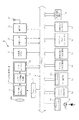
図2は、親機Aの構成を示すブロック図である。図において画像取得部1は、撮像レンズ101とズーム駆動部102及びLPF103を備えている。撮像レンズ101はズーム機能を備えた光学系であり、ズーム駆動部102はドライバ3により制御されて撮像レンズ101を駆動するステッピングモータ等を有してなる。LPF103は、水晶ローパスフィルターであって、モアレの発生を防止すべく搭載されている。
FIG. 2 is a block diagram showing a configuration of base unit A. In the figure, the
この画像取得部1の後段には、CCD、CMOS等の撮像センサ201と、サンプリング/信号処理部202、及びADコンバータ203とを有するアナログ信号処理部2が配置されている。撮像センサ201は、LPF103を介して撮像レンズ101により結像された被写体画像のRGBの各色の強さを電流値に変換する。また、撮像センサ201は、制御部5が設定した電荷蓄積時間がシャッターパルスとして、ドライバ3に供給され、これに従いドライバ3が撮像センサ201を駆動することにより電荷蓄積時間すなわち露光時間が制御される。つまり撮像センサ201は電子シャッターとして機能する。サンプリング/信号処理部202は、撮像センサ201からの画像信号のノイズや色むらを抑えるために相関二重サンプリング処理や信号増幅処理を行う。ADコンバータ203は、サンプリング/信号処理部202がサンプリング・増幅したアナログ信号をデジタル信号に変換し、RGB、CYMG各色について12bitデータに変換してバスライン4に出力する。
An analog
制御部5は、CPU及びその周辺回路と、CPUの作業用メモリであるRAM等を有するマイクロコンピュータであり、後述するプログラムメモリ16に格納されるプログラムに基づいて、このデジタルカメラ全体を制御する。プレビューエンジン6は、アナログ信号処理部2を介して入力されたデジタルデータ、若しくはシャッター操作検出後イメージバッファ12に格納されたデジタルデータ、及び画像メモリ17に格納されたデジタルデータを表示部9に表示させるための間引き処理を行う回路部である。D/Aコンバータ7は、プレビューエンジン6により間引きされたデジタルデータを変換し、後段のドライバ8に出力する。ドライバ8は、後段の表示部9に表示されるデジタルデータを一時記憶するバッファ領域を備え、キー操作部13、制御部5を介して入力された制御信号に基づいて制御部5を駆動する。表示部9は、プレビュー画像を表示可能なカラーTFT液晶からなる。
The
フラッシュコントローラー10は、ストロボフラッシュ用のLED11を制御するものであり、ストロボ発光の際の充電制御も兼ねる。イメージバッファ(SDRAM)12は、アナログ信号処理部2又はデジタル信号処理部14を介して入力され、デジタル信号処理部14で処理されるデジタルデータを一時的に格納する領域である。キー操作部13は、シャッターキー131及び不図示のズームキー、記録/再生モード、記録モードにおける動画撮影モードへの切り換えキー、十字キー、メニューキー等の外部操作手段を備える。そして、後述するフローチャートに示す各種モードは、ユーザによるメニューキー等の操作により設定される。
The
デジタル信号処理部14は、アナログ信号処理部2を介して入力されたデジタルデータ(非圧縮のRAWイメージデータ)について、ホワイトバランス処理、色処理、階調処理、輪郭強調を行う。画像圧縮/伸張処理部15は、デジタル信号処理部14を介して入力されたデジタルデータ(非圧縮のRAWイメージデータ)をJPEG方式やMPEG方式に圧縮符号化したり、再生モードにおいては、JPEG形式のファイルやMPEG形式のファイルを伸長する。動画撮影の場合は、アナログ信号処理部2→イメージバッファ12→デジタル信号処理部14→圧縮/伸張処理部15まで、一連の動作を行って動画ファイル(JPEG2000形式、MPEG−4形式のファイル)を作成する。
The digital
プログラムメモリ(NAND Flash ROM)16は、制御部5にロードされる各種プログラムを格納するとともに、EV値、色補正情報等の各種情報をテーブル単位で格納しており、またDCF規格に準拠されているファイルに埋め込む各種情報も記憶している。画像メモリ17は、ファイル形式に変換されたデジタルデータを格納する。カードI/F18は、外部記録媒体19とこのデジタルカメラとの間のデータ変換をサポートするものであり、外部記録媒体19は、コンパクトフラッシュ(登録商標)、メモリースティック、SDカード等の着脱自在なメモリからなる。外部接続用I/F20は、USBコネクター用スロットからなる。通信部21は、子機Bと所定の周波数で無線通信を行ってデータやコマンドを送受信するものであり、アンテナ22が接続されている。
The program memory (NAND Flash ROM) 16 stores various programs loaded into the
図3は、子機Bの構成を示すブロック図である。前述のように、子機Bは親機Aよりも低機能な簡易型のデジタルカメラであって、ズーム機能を有しておらず、レンズ104の撮影光軸後方にアナログ信号処理部2が配置されている。アナログ信号処理部2において、撮像センサ201の解像度は親機Aのそれよりも低い。また、子機Bは光学ファインダーのみを有する機種であり、それ故、親機Aが備えていた前記表示部9、及びこの表示部9に関連する回路部であるドライバ8、D/Aコンバータ7を備えていない。更に、子機Bは、画像メモリ17にのみ画像を記録可能であり、よって、前記外部記録媒体19及びカードI/Fも備えておらず、画像メモリ17の記憶容量も親機Aのそれよりも小さい。また、キー操作部13は、シャッターキー131は備えているが他のキーの数は親機Aのキーの数より遙かに少ない。なお、他の構成は図2に示した親機Aと同一であるので、同一部分に同一符号を付して説明を省略する。
FIG. 3 is a block diagram showing the configuration of the slave unit B. As shown in FIG. As described above, the slave unit B is a simple digital camera having a lower function than the master unit A, does not have a zoom function, and the analog
但し、子機Bは親機Aと異なり、状態センサ23を有している。この状態センサ23は、子機Bの機器本体の向きに応じた検出信号a、bを制御部5にバスライン4を介して出力するものである。
However, unlike the parent device A, the child device B has a
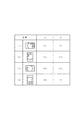
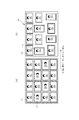
図4は、状態センサ23が出力する検出信号a、bと子機Bの機器本体の向きとの関係を示す図である。図示のように、この状態センサ23は、子機Bのレンズ104(図1参照)が正面右に位置する状態が通常状態(状態(1))であり、このとき検出信号a、bは共にONとなる。また、レンズ104が上部に位置する上縦置き状態(状態(2))では、検出信号aはON、検出信号bはOFFである。レンズ104が左に位置する天地逆転状態(状態(3))では、検出信号a、bは共にOFFである。レンズ104が下部に位置する下縦置き状態(状態(4))では、検出信号aはOFF、検出信号bはONである。したがて、これら検出信号a,bのON、OFFを示すデータを撮影した画像とともに記録することにより、当該画像が状態(1)〜(4)のいずれで撮影されたものであるかを認識することが可能である。
FIG. 4 is a diagram illustrating a relationship between the detection signals a and b output from the
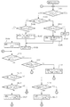
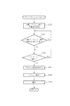
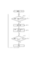
以上の構成に係る本実施の形態において、子機Bの制御部5はプログラムメモリ16からロードしたプログラムに基づき、図5に示すフローチャートに従って処理を実行する。すなわち、ユーザにより接続モードが設定されたか否かを判断し(ステップB1)、接続モードが設定されていない場合には、後述するデジタルカメラとしての通常の動作処理を実行する(ステップB2)。接続モードが設定された場合には、通信部21を起動して親機Aと無線接続させる(ステップB3)。更に、親機Aと無線接続状態となったか否かを判断し(ステップB4)、接続状態となっていない場合には一定回数以上接続動作を行ったか否かを判断する(ステップB5)。一定回数以上接続動作を行っていない場合には、ステップB3に戻って接続処理を実行し、一定回数以上接続動作を行っても親機Aと接続状態にならない場合には、接続エラーとする(ステップB6)。
In the present embodiment having the above configuration, the
また、ステップB4での判断の結果、親機Aと無線接続状態となった場合には、親機Aとの通信に基づき、親機Aはデータ処理モードであるか否かを判断し(ステップB7)、データ処理モードである場合には、後述するデータ処理・加工シーケンスへ移行する(ステップB8)。親機Aがデータ処理モードでない場合には(ステップB7;NO)、親機Aは閲覧モードであるか否かを判断し(ステップB9)、閲覧モードである場合には、後述する閲覧シーケンスへ移行する(ステップB10)。 If the result of determination in step B4 is that the base unit A is in a wireless connection state, based on communication with the base unit A, it is determined whether the base unit A is in the data processing mode (step B7) If in the data processing mode, the process proceeds to a data processing / processing sequence described later (step B8). If the parent device A is not in the data processing mode (step B7; NO), it is determined whether or not the parent device A is in the browsing mode (step B9). Transition (step B10).
また、親機Aが閲覧モードでない場合には(ステップB9:NO)、親機Aは撮影モードであるか否かを判断する(ステップB11)。撮影モードである場合には、更に親機Aはレリーズモードである否かを判断し(ステップB12)、レリーズモードである場合には後述するレリーズ撮影モードシーケンスへ移行する(ステップB13)。レリーズモードでない場合には(ステップB13:NO)、親機Aはリモートフラッシュモードである否かを判断する(ステップB14)。そして、リモートフラッシュモードである場合には、後述するリモートフラッシュシーケンスへ移行し(ステップB15)、リモートフラッシュモードでない場合には、その他のモードへ移行する(ステップB18)。 If the parent device A is not in the browsing mode (step B9: NO), it is determined whether the parent device A is in the photographing mode (step B11). If it is in the shooting mode, the base unit A further determines whether or not it is in the release mode (step B12). If it is in the release mode, the process proceeds to a release shooting mode sequence described later (step B13). When the release mode is not set (step B13: NO), the base unit A determines whether or not the remote flash mode is set (step B14). If the remote flash mode is selected, the process proceeds to a remote flash sequence described later (step B15). If the remote flash mode is not selected, the process proceeds to another mode (step B18).
また、ステップB11での判断結果、親機Aが撮影モードでない場合には、親機Aはコントロールモードであるか否かを判断し(ステップB16)、コントロールモードである場合には、後述するコントロールシーケンスへ移行し(ステップB17)、コントロールモードでない場合には、前記その他のモードへ移行する(ステップB18)。 If the result of determination in step B11 is that the parent device A is not in the shooting mode, it is determined whether or not the parent device A is in the control mode (step B16). The process proceeds to the sequence (step B17), and if not in the control mode, the process proceeds to the other mode (step B18).
図6は、図5のフローチャートにおける前記「デジタルカメラとして通常動作処理」(ステップB2)の処理手順を示すフローチャートである。すなわち、シャッターキー131が操作されたか否かを判断し(ステップB21)、操作されたならば、撮影処理を行って、イメージバッファ12にシャッターキー131が操作された直後の画像データを取り込み、この画像データを画像メモリ17に記録する(ステップB22)。更に、状態センサ23の検出信号a、bの値(ON、OFF)を各画像データの画像情報に記録する(ステップB23)。したがって、子機Bの画像メモリ17には、撮影された被写体の画像データのみならず、そのとき子機Bが前記(1)〜(4)のいずれの状態で撮影されたかを示す検出信号a、bの値(ON、OFF)も記録されることとなる。
FIG. 6 is a flowchart showing a processing procedure of the “normal operation processing as a digital camera” (step B2) in the flowchart of FIG. That is, it is determined whether or not the
図7は、前記「データ処理・加工シーケンス」(ステップB8)における子機データ移送シーケンスの処理手順を示すフローチャートである。すなわち、子機Bの画像メモリ17に記録されている全ての画像データと画像情報(検出信号a、bの値(ON、OFF))とを含む撮影ファイル情報を一括して親機Aに転送し(ステップB81)、データ処理・加工シーケンスを終了する(ステップB82)。
FIG. 7 is a flowchart showing the processing procedure of the slave unit data transfer sequence in the “data processing / processing sequence” (step B8). That is, shooting file information including all image data and image information (values of detection signals a and b (ON and OFF)) recorded in the
図8は、図7のフローチャートに示した子機B側の処理である子機データ移送シーケンスに対応する親機A側の処理であるデータ移動シーケンスの処理手順を示すフローチャートである。まず、メモリカード(外部記録媒体19)上に、制御部5が有する時計部で計時した日から生成した名前、つまり現在日付で生成した名称で子機保存用ディレクトリを作成する(ステップA81)。更に、前記ステップB81での処理により子機Bから転送されてきた子機Bの撮影データ(画像データと画像情報(検出信号a、bの値(ON、OFF))とを含む撮影ファイル)を前記ディレクトリに移送する(ステップA82)。引き続き、状態センサ23の情報に従って画像を回転して前記ディレクトリに記憶させる(ステップA83)。
FIG. 8 is a flowchart showing a processing procedure of a data movement sequence which is a process on the parent device A side corresponding to a child device data transfer sequence which is a process on the child device B side shown in the flowchart of FIG. First, a slave storage directory is created on the memory card (external recording medium 19) with the name generated from the date counted by the clock unit of the
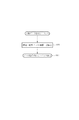
すなわち、子機Bにおいては、前記図4に示した状態(1)〜(4)のいずれでも撮影が可能である。このとき、状態(1)で撮影した場合には、その画像は図9(a)に示す横画像P1となり、状態(2)で撮影した場合には縦画像P2となる。よって、これら画像P1、P2を単に記憶させると、同図に示すように縦画像P2の被写体は横向きとなる。しかし、状態センサ23の情報に従って画像P2を90°回転させることにより、図9(b)に示すように、各画像の被写体を正常な縦向きにして、外部記録媒体19の前記ディレクトリに記録することができる。
That is, the slave unit B can shoot in any of the states (1) to (4) shown in FIG. At this time, when the image is captured in the state (1), the image is the horizontal image P1 shown in FIG. 9A, and when the image is captured in the state (2), the image is the vertical image P2. Therefore, when these images P1 and P2 are simply stored, the subject of the vertical image P2 is turned sideways as shown in FIG. However, by rotating the image P2 by 90 ° in accordance with the information from the
また、前述のように親機Aは外部記録媒体19を脱着可能に備える一方、子機Bは外部記録媒体19を備えていない。しかし、子機Bから親機Aに転送して親機A側の外部記録媒体19に画像を記録させた後、これを親機Aから取り外し、図1に示したコンビニエンスストア等に配置された印刷機Cでプリントアウトすることにより、子機B側で撮影された画像を外部機器でプリントアウトすることも可能となる。
Further, as described above, the master unit A includes the
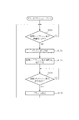
図10は、図7のフローチャートに示した子機B側の処理である子機データ移送シーケンスに対応する親機A側の処理であるデータ移動シーケンスにおけるデータ連結シーケンスの処理手順を示すフローチャートである。まず、前述の図8のフローチャートで子機Bから移送した画像データのディレクトリを表示部9にメニュー表示させ(ステップA801)、ユーザの操作に応じていずれかのディレクトリを選択する(ステップA802)。更に、この選択したディレクトリ内の全てのファイルをサムネイルプレビュー表示して、ディレクトリ内ファイルの各縮小画像を表示部9に表示させる(ステップA803)。
FIG. 10 is a flowchart showing the processing procedure of the data connection sequence in the data movement sequence which is the process on the parent device A side corresponding to the child device data transfer sequence which is the processing on the child device B side shown in the flowchart of FIG. . First, the menu of the directory of the image data transferred from the slave unit B is displayed on the
また、ユーザの操作に応じて、サムネイルプレビューの連結に使う画像を選択し(ステップA804)、連結を開始する(ステップA805)。すなわち、親機Aのイメージバッファ12上に選択された画像を展開し(ステップA806)、前回展開した画像の右側に今回展開した画像を移動して配置する(ステップA807)。したがって、図11(a)に示すように、子機Bから送信されて選択されたディレクトリに記憶されている画像群から、画像P001が選択された後画像P002が選択されたとすると、同図(b)に示すように、画像P001の右側に画像P002が配置されることとなる。
Further, in accordance with the user's operation, an image to be used for connecting thumbnail previews is selected (step A804), and connection is started (step A805). That is, the selected image is developed on the
引き続き、画像が所定の右端まで配置されたか否かを判断する(ステップA808)。つまり、図11(b)に示すように、横方向に4枚の画像を配置する形態であるとすると、画像P003までが配置された状態では、その右側に1枚分の配置スペースが残存しており、画像が所定の右端まで配置されていない。よって、この場合には、ステップA808の判断がNOとなり、ステップA806からの処理を再度実行する。したがって、ステップA806及びA807の再度実行されることにより、画像P003の右側に画像P004が配置されることとなる。 Subsequently, it is determined whether or not the image is arranged up to a predetermined right end (step A808). That is, as shown in FIG. 11B, assuming that the four images are arranged in the horizontal direction, the arrangement space for one image remains on the right side when the image P003 is arranged. The image is not arranged up to a predetermined right end. Therefore, in this case, the determination in step A808 is NO, and the processing from step A806 is executed again. Therefore, by executing Steps A806 and A807 again, the image P004 is arranged on the right side of the image P003.
また、このように画像P003の右側に画像P004が配置されると、画像が右端まで配置されてステップA808の判断がYESとなる。よって、ステップA808からステップA809に進み、これまで表示した画像の最下端+1の座標に展開する位置を移動する(ステップA09)。更に、展開する位置を「最下端+1」における左端に移動して、前述したステップA806からの処理を実行する。これにより、図11(b)に示したように、ディレクトリから選択した画像が4列で表示部9に表示されることとなる。無論、所定の記憶操作によりこれら表示部9に表示された画像群のデータを外部記録媒体19に記録させることができる。
Further, when the image P004 is arranged on the right side of the image P003 in this way, the image is arranged to the right end, and the determination in step A808 becomes YES. Therefore, the process proceeds from step A808 to step A809, and the position where the image is expanded to the coordinate of the lowest end + 1 of the images displayed so far is moved (step A09). Further, the position to be developed is moved to the left end at “bottom end + 1”, and the processing from step A806 described above is executed. As a result, as shown in FIG. 11B, the images selected from the directory are displayed on the
なお、本実施の形態においては、データ移動シーケンスの場合を示したが、図12に示すデータ移動コメント付加画像連結シーケンスを行って、ディレクトリから選択された画像P001〜P004・・・を適宜の間隔を置いて表示部9に表示させ、各画像の側部にユーザにより入力コメントCを付加して表示させ、更にはこれを外部記録媒体19に記録させるようにしてもよい。また、図13に示すデータ移動画像シーケンスを行って、表示部9の前面に展開した親機Aで撮影した画像PAの一部に、ディレクトリから選択した画像P001を合成して表示させ、更にはこれを外部記録媒体19に記録させるようにしてもよい。
In the present embodiment, the case of the data movement sequence is shown. However, the data movement comment added image concatenation sequence shown in FIG. 12 is performed, and the images P001 to P004. May be displayed on the
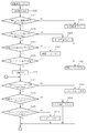
図14は、前記図5のフローチャートにおける「閲覧シーケンス」(ステップB10)の処理手順を示すフローチャートである。すなわち、シャッターキー131が操作されたか否かを判断し(ステップB101)、操作されたならば、状態センサ23からの検出信号aがON、OFFのいずれであるかを判断する(ステップB102)。検出信号aがOFFであるならば、更に、検出信号bがON、OFFのいずれであるかを判断する(ステップB103)。そして、検出信号a,bが共にOFFであるならば、閲覧を終了する(ステップB104)。したがって、閲覧シーケンスにおいてシャッターキー131を1回操作した後、図4(3)に示したように、子機Bを天地逆転状態にすると、閲覧シーケンスが終了する。
FIG. 14 is a flowchart showing the processing procedure of the “browsing sequence” (step B10) in the flowchart of FIG. That is, it is determined whether or not the
また、ステップB103での判断の結果、検出信号bがONであり、よって、検出信号aがOFFかつ検出信号bがONの場合には、親機Aへ「前の画像に戻る」信号を送信する(ステップB105)。したがって、閲覧シーケンスにおいてシャッターキー131を1回操作した後、図4(4)に示したように、子機Bをレンズ104が下部に位置する下縦置き状態にすると、子機Bから親機Aに「前の画像に戻る」信号が送信される。
As a result of the determination in step B103, if the detection signal b is ON, and therefore the detection signal a is OFF and the detection signal b is ON, a “return to previous image” signal is transmitted to the main unit A. (Step B105). Therefore, after the
また、ステップB102での判断の結果、検出信号aがONであるならば、更に、検出信号bがON、OFFのいずれであるかを判断する(ステップB106)。そして、検出信号bがOFFであり、よって、検出信号aがONかつ検出信号bがOFFの場合には、親機Aへ「次の画像を表示」信号を送信し(ステップB107)、このフローチャートの先頭に戻る(ステップB108)。したがって、閲覧シーケンスにおいてシャッターキー131を1回操作した後、図4(2)に示したように、子機Bをレンズ104が上部に位置する上縦置き状態にすると、子機Bから親機Aに「次の画像を表示」信号が送信される。
If the detection signal a is ON as a result of the determination in step B102, it is further determined whether the detection signal b is ON or OFF (step B106). If the detection signal b is OFF, and therefore the detection signal a is ON and the detection signal b is OFF, a “display next image” signal is transmitted to the parent device A (step B107). (Step B108). Therefore, after the
また、ステップB106での判断の結果、検出信号bがONであり、よって、検出信号a、bが共にONの場合には、親機Aへ「ズーム」信号を送信する(ステップB109)。したがって、閲覧シーケンスにおいてシャッターキー131を1回操作した後、図4(1)に示したように、子機Bを通常状態にすると、子機Bから親機Aに「ズーム」信号が送信される。
If the detection signal b is ON as a result of the determination in step B106, and therefore both the detection signals a and b are ON, a “zoom” signal is transmitted to the parent device A (step B109). Therefore, after the
また、ステップB109続くステップB110では、シャッターキー131が再度操作されたか否かを判断し、シャッターキー131が再度操作されたならば、検出信号a、bが共にOFFであるか否かを判断する(ステップB111)。検出信号a、bが共にOFFではない場合には、親機Aへ「スクロール方向切替(縦横)」信号を送信する(ステップB112)。したがって、閲覧シーケンスにおいてシャッターキー131を2回操作した後、図4(1)(2)(4)に示したように、子機Bを通常状態、レンズ104が上部に位置する上縦置き状態、レンズ104が下部に位置する下縦置き状態のいずれかにすると、子機Bから親機Aに「スクロール方向切替(縦横)」信号が送信される。
In step B110 following step B109, it is determined whether or not the
また、ステップB110での判断の結果、シャッターキー131が再度操作されない場合には、検出信号aがON、OFFのいずれであるかを判断する(ステップB103)。検出信号aがONであるならば、更に、検出信号bがON、OFFのいずれであるかを判断する(ステップB114)。そして、検出信号bがOFFであり、よって、検出信号aがONかつ検出信号bがOFFの場合には、親機Aへ「マイナス方向にスクロール」信号を送信する(ステップB115)。したがって、閲覧シーケンスにおいて、図4(2)に示したように、レンズ104が上部に位置する上縦置き状態に変化させると、子機Bから親機Aに「マイナス方向にスクロール」信号が送信される。
If the result of determination in step B110 is that the
また、ステップB113での判断の結果、検出信号aがOFFであるならば、更に、検出信号bがON、OFFのいずれであるかを判断する(ステップB116)。そして、検出信号bがONであり、よって、検出信号aがOFFかつ検出信号bがONの場合には、親機Aへ「プラス方向にスクロール」信号を送信する(ステップB117)。したがって、閲覧シーケンスにおいて、図4(4)に示したように、子機Bをレンズ104が下部に位置する下縦置き状態に変化させると、子機Bから親機Aに「プラス方向にスクロール」信号が送信される。
If the detection signal a is OFF as a result of the determination in step B113, it is further determined whether the detection signal b is ON or OFF (step B116). If the detection signal b is ON, and therefore the detection signal a is OFF and the detection signal b is ON, a “plus direction scroll” signal is transmitted to the parent device A (step B117). Therefore, in the browsing sequence, as shown in FIG. 4 (4), when the handset B is changed to a vertically placed state in which the
図15は、図14に示した子機B側の閲覧シーケンスに対応する親機A側の閲覧シーケンスの処理手順を示すフローチャートである。先ず、画像メモリ17又は外部記録媒体19に記録されている撮影画像を表示部9に表示させる(ステップA101)。次に、子機Bから「次の画像表示」信号を受信したか否かを判断する(ステップA102)。「次の画像表示」信号を受信したならば、表示画像番号をインクリメントして(ステップA103)、この閲覧シーケンスの先頭へ戻り(ステップA109)、次の画像番号の撮影画像を表示部9に表示させる(ステップA101)。
FIG. 15 is a flowchart showing the processing sequence of the browsing sequence on the parent device A side corresponding to the browsing sequence on the child device B side shown in FIG. First, the captured image recorded in the
また、「次の画像表示」信号を受信しなかった場合には、子機Bから「前の画像に戻る」信号を受信したか否かを判断する(ステップA104)。「前の画像に戻る」信号を受信したならば、表示画像番号をデクリメントして(ステップA105)、この閲覧シーケンスの先頭へ戻り(ステップA109)、前の画像番号の撮影画像を表示部9に表示させる(ステップA101)。
If the “next image display” signal has not been received, it is determined whether or not a “return to previous image” signal has been received from handset B (step A104). If the "return to previous image" signal is received, the display image number is decremented (step A105), the process returns to the beginning of this browsing sequence (step A109), and the captured image with the previous image number is displayed on the
また、「前の画像に戻る」信号を受信しなかった場合には、子機Bから「閲覧終了」信号を受信したか否かを判断する(ステップA106)。「閲覧終了」信号を受信したならば、この閲覧シーケンスを終了する(ステップA107)。また、「閲覧終了」信号を受信しなかった場合には、子機Bから「ズーム」信号を受信したか否かを判断する(ステップA108)。「ズーム」信号を受信しなかった場合には、この閲覧シーケンスの先頭へ戻り(ステップA109)、「ズーム」信号を受信したならば、表示部9に表示されている画像を拡大する(ステップA110)。
If the “return to previous image” signal has not been received, it is determined whether or not the “viewing end” signal has been received from handset B (step A106). When the “browsing end” signal is received, this browsing sequence is terminated (step A107). If the “browsing end” signal is not received, it is determined whether or not the “zoom” signal is received from the slave unit B (step A108). If the “zoom” signal has not been received, the process returns to the beginning of this browsing sequence (step A109). If the “zoom” signal is received, the image displayed on the
次に、子機Bから「スクロール方向切替」信号を受信したか否かを判断する(ステップA111)。「スクロール方向切替」信号を受信したならば、スクロール方向を切り替える(ステップA112。)。「スクロール方向切替」信号を受信しなかった場合には、子機Bから「マイナス方向にスクロール」信号を受信したか否かを判断する(ステップA113)。「マイナス方向にスクロール」信号を受信したならば、表示部9に表示されている画像をマイナス方向(逆方向)にスクロールする(ステップA114)。「マイナス方向にスクロール」信号を受信しなかった場合には、子機Bから「プラス方向にスクロール」信号を受信したか否かを判断する(ステップA115)。「プラス方向にスクロール」信号を受信したならば、表示部9に表示されている画像をプラス方向(順方向)にスクロールする(ステップA116)。
Next, it is determined whether or not a “scroll direction switching” signal is received from the slave unit B (step A111). If the “scroll direction switching” signal is received, the scroll direction is switched (step A112). If the “scroll direction switching” signal has not been received, it is determined whether or not the “scrolling in the minus direction” signal has been received from the slave unit B (step A113). If the “scroll in the minus direction” signal is received, the image displayed on the
したがって、前述した図14のフローチャートに従った子機B側の処理と、この図15に示したフローチャートに従った親機A側の処理とにより、閲覧シーケンスにおいて子機Bの向きを変化させることより、親機Aの画像表示をリモートコントロールすることができる。 Therefore, the orientation of the slave unit B is changed in the browsing sequence by the processing on the slave unit B side according to the flowchart of FIG. 14 described above and the process on the master unit A side according to the flowchart of FIG. Thus, the image display of the master unit A can be remotely controlled.
図16は、前記図5のフローチャートにおける「レリーズ撮影シーケンス」(ステップB13)の処理手順を示すフローチャートである。すなわち、子機Bにおいてシャッターキー131が操作されたか否かを判断し(ステップB131)、操作されたならば、親機Aへ「シャッターを切る」信号を送信する(ステップB132)。
FIG. 16 is a flowchart showing the processing procedure of the “release photography sequence” (step B13) in the flowchart of FIG. That is, it is determined whether or not the
図17は、図16に示した子機B側のレリーズ撮影シーケンスに対応する親機A側のレリーズ撮影シーケンスの処理手順を示すフローチャートである。子機Bから「シャッターを切る」信号を受信したか否かを判断する(ステップA131)。「シャッターを切る」信号を受信したならば、撮影処理を行って、イメージバッファ12に「シャッターを切る」信号を受信した直後の画像データを取り込み、この画像データを画像メモリ17又は外部記録媒体19に記録する(ステップB132)。
FIG. 17 is a flowchart showing a processing procedure of the release shooting sequence on the parent device A side corresponding to the release shooting sequence on the child device B side shown in FIG. It is determined whether or not a “shutter release” signal has been received from slave unit B (step A131). When the “shutter release” signal is received, shooting processing is performed, and image data immediately after the reception of the “shutter release” signal is taken into the
したがって、親機Aを所望の位置に配置し、これから離れた位置で子機Bにてシャッターキー131の操作を行うことにより、親機Aをリモートコントロールして撮影を行うことができる。
Therefore, by placing the master unit A at a desired position and operating the
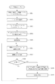
図18は、前記図5のフローチャートにおける「リモートフラッシュシーケンス」(ステップB15)に対応する親機A側のリモートフラッシュシーケンスの処理手順を示すフローチャートである。すなわち、子機Bへフラッシュ発光準備要求を送信し(ステップA151)、この要求に応じて子機Bから送信される「フラッシュ発光準備OK」を受信するまで待機する(ステップA152)。子機Bからの「フラッシュ発光準備OK」を受信したならば(ステップA152;YES)、シャッターキー131が操作されたか否かを判断する(ステップA153)。シャッターキー131が操作されたならば、子機Bにフラッシュ発光信号を送信し(ステップA154)、フラッシュコントローラー10に指示し、ストロボフラッシュ用のLED11を発光させる(ステップA155)。更に、撮影処理を行って、イメージバッファ12にLED11を発光させた直後の画像データを取り込み、この画像データを画像メモリ17又は外部記録媒体19に記録する(ステップA156)。
FIG. 18 is a flowchart showing the processing procedure of the remote flash sequence on the base A side corresponding to the “remote flash sequence” (step B15) in the flowchart of FIG. That is, a flash emission preparation request is transmitted to the slave unit B (step A151), and the process waits until receiving “flash emission preparation OK” transmitted from the slave unit B in response to this request (step A152). If the “flash emission preparation OK” from the slave unit B is received (step A152; YES), it is determined whether or not the
図19は、前記図5のフローチャートにおける「リモートフラッシュシーケンス」(ステップB15)の処理手順を示すフローチャートである。前記ステップA151で親機Aから送信されるフラッシュ発光準備要求があるまで待機する(ステップB151)。フラッシュ発光準備要求があったならば、フラッシュコントローラー10を制御してストロボ発光の際の充電制御等のフラッシュ発光準備を行った後(ステップB152)、親機Aへフラッシュ発行準備OK信号を送信する(ステップB152)。そして、親機Aからのフラッシュ発光信号を受信するまで待機し(ステップB154)、フラッシュ発光信号を受信したならば、フラッシュコントローラー10に指示し、ストロボフラッシュ用のLED11を発光させる(ステップB155)。
FIG. 19 is a flowchart showing the processing procedure of the “remote flash sequence” (step B15) in the flowchart of FIG. It waits until there is a flash emission preparation request transmitted from the parent device A in the step A151 (step B151). If there is a request for flash emission preparation, the
したがって、前述した図18のフローチャートに従った子機B側の処理と、この図19に示したフローチャートに従った親機A側の処理とによるリモートフラッシュシーケンスにより、子機Bを親機Aから遠隔操作し、図20に示すように、親機Aの外部フラッシュとして用いることができる。これにより、夜間等において親機A内蔵のフラッシュでは光量が足りないロングショットの撮影などに、被写体付近に子機Bを配置することにより、撮影に必要な光量を確保することができる。 Therefore, the slave unit B is moved from the master unit A by the remote flash sequence according to the process on the slave unit B side according to the flowchart of FIG. 18 and the process on the master unit A side according to the flowchart shown in FIG. It can be remotely operated and used as an external flash of the main unit A as shown in FIG. As a result, the light quantity necessary for photographing can be ensured by arranging the handset B near the subject for shooting long shots where the amount of light is insufficient with the flash built in the parent machine A at night or the like.
図21は、前記図5のフローチャートの「コントロールシーケンス」(ステップB17)におけるリモート撮影シーケンスに対応する親機A側のリモート撮影シーケンスの処理手順を示すフローチャートである。すなわち、子機Bへ撮影準備要求を送信し(ステップA171)、この要求に応じて子機Bから送信される「撮影準備OK」を受信するまで待機する(ステップA172)。子機Bからの「撮影準備OK」を受信したならば(ステップA172;YES)、シャッターキー131が操作されたか否かを判断する(ステップA173)。シャッターキー131が操作されたならば、子機Bに撮影信号を送信し(ステップA174)、撮影処理を行って、イメージバッファ12に画像データを取り込み、この画像データを画像メモリ17又は外部記録媒体19に記録する(ステップA175)。
FIG. 21 is a flowchart showing the processing procedure of the remote shooting sequence on the base A side corresponding to the remote shooting sequence in the “control sequence” (step B17) of the flowchart of FIG. That is, a photographing preparation request is transmitted to the child device B (step A171), and the apparatus waits for reception of “photographing preparation OK” transmitted from the child device B in response to this request (step A172). If “photographing preparation OK” is received from the slave unit B (step A172; YES), it is determined whether or not the
図22は、前記図5のフローチャートの「コントロールシーケンス」(ステップB17)におけるリモート撮影シーケンス処理手順を示すフローチャートである。前記ステップA171で親機Aから送信される撮影準備要求があるまで待機する(ステップB171)。撮影準備要求があったならば、撮影準備を行った後(ステップB172)、親機Aへ撮影発行準備OK信号を送信する(ステップB172)。そして、親機Aからの撮影信号を受信するまで待機し(ステップB174)、撮影信号を受信したならば、撮影処理を行って、イメージバッファ12に画像データを取り込み、この画像データを画像メモリ17に記録する(ステップA175)。
FIG. 22 is a flowchart showing a remote photographing sequence processing procedure in the “control sequence” (step B17) of the flowchart of FIG. It waits until there is a photographing preparation request transmitted from the parent device A in step A171 (step B171). If there is a shooting preparation request, after shooting preparation is performed (step B172), a shooting issue preparation OK signal is transmitted to the parent device A (step B172). Then, it waits until it receives a photographic signal from the main unit A (step B174). If a photographic signal is received, it performs a photographing process, takes image data into the
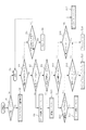
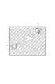
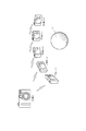
したがって、前述した図21のフローチャートに従った子機B側の処理と、この図22に示したフローチャートに従った親機A側の処理とによるリモート撮影シーケンスを、図23に示したように複数の子機B−1〜B−5を用いて行うことにより、親機Aによって全体を撮影し、複数の子機B−1〜B−5によって被写体Oを異なる角度から撮影した画像を一瞬にして記録することができる。よって、マルチアングルの同時撮影や監視カメラ的な使用形態が可能となる。 Therefore, as shown in FIG. 23, a plurality of remote photographing sequences are performed by the processing on the slave unit B side according to the flowchart of FIG. 21 and the processing on the master unit A side according to the flowchart shown in FIG. By using the slave units B-1 to B-5, the whole image is taken by the master unit A, and images of the subject O taken from different angles by the plurality of slave units B-1 to B-5 are instantly displayed. Can be recorded. Therefore, simultaneous use of multiple angles and usage forms like a surveillance camera are possible.
また、撮影スケジューリングが可能なマクロ言語を用いることにより、動画撮影時において、子機B−1で1〜12フレームまで、子機B−2で13フレーム目、子機B−3で14フレーム目、子機B−4で15フレーム目、子機B−5で16〜24フレーム、子機B−4で25フレーム目、子機B−3で26フレーム目、子機B−2で27フレーム目、子機B−1で28フレーム目以降を撮影すれば、所謂マシンガン撮影のような連続的な撮影を行うことも可能となる。 In addition, by using a macro language capable of shooting scheduling, at the time of moving image shooting, the slave unit B-1 has 1 to 12 frames, the slave unit B-2 has the 13th frame, and the slave unit B-3 has the 14th frame. , 15th frame for handset B-4, 16-24th frame for handset B-5, 25th frame for handset B-4, 26th frame for handset B-3, 27th frame for handset B-2 If the 28th and subsequent frames are photographed with the eye and the slave unit B-1, continuous photographing such as so-called machine gun photographing can be performed.
なお、本実施の形態においては、前記図5のフローチャートの「コントロールシーケンス」(ステップB17)の一例としてリモート撮影シーケンスを示したが、コントロールシーケンスはこれに限らず、親機Aにモニターを有線接続し、子機B側での操作により親機Aからモニターへのビデオ出力を制御するようにしてもよい。また、実施の形態においては、親機Aと子機Bとを無線接続した場合を示したが、親機Aと子機Bの外部接続用I/F20同士をUSBケーブルで有線接続して、前述した処理と同様の処理を有線で行うようにしてもよい。更に実施の形態においては、本発明をデジタルカメラに適用した場合について説明したが、撮影機能を有する機器であれば、デジタルカメラ以外の他の機器であっても本発明を適用することができる。
In the present embodiment, the remote photographing sequence is shown as an example of the “control sequence” (step B17) in the flowchart of FIG. 5, but the control sequence is not limited to this, and a monitor is connected to the parent device A by wire. Then, the video output from the parent device A to the monitor may be controlled by an operation on the child device B side. Further, in the embodiment, the case where the parent device A and the child device B are wirelessly connected is shown. However, the external connection I /
A 親機
B 子機
1 画像取得部
2 アナログ信号処理部
5 制御部
6 プレビューエンジン
9 表示部
10 フラッシュコントローラー
11 LED
12 イメージバッファ
13 キー操作部
16 プログラムメモリ
17 画像メモリ
19 外部記録媒体
20 外部接続用I/F
21 通信部
22 アンテナ
23 状態センサ
131 シャッターキー
201 撮像センサ
202 サンプリング/信号処理部
203 ADコンバータ
A Master unit
12
21
Claims (15)
前記第1の撮像装置は、撮像された画像情報を前記第2の撮像装置に無線送信する画像情報送信手段を備え、
前記第2の撮像装置は、
前記第1の撮像装置から無線送信される画像情報を受信する画像情報受信手段と、
この画像情報受信手段により受信された画像情報を記憶する第1の記憶手段と、
当該装置で撮像された画像情報を記憶する第2の記憶手段と、
前記第1の記憶手段に記憶された画像情報と前記第2の記憶手段に記憶された画像情報とを一覧表示する表示手段と
を備えることを特徴とする画像通信システム。 An image communication system comprising a first imaging device and a second imaging device,
The first imaging device includes image information transmission means for wirelessly transmitting captured image information to the second imaging device,
The second imaging device includes:
Image information receiving means for receiving image information wirelessly transmitted from the first imaging device;
First storage means for storing image information received by the image information receiving means;
Second storage means for storing image information captured by the device;
An image communication system comprising: display means for displaying a list of image information stored in the first storage means and image information stored in the second storage means.
前記第1の撮像装置は、
前記第2の撮像装置から送信された制御情報を無線受信する制御情報受信手段と、
この制御情報受信手段によって無線受信された制御情報に従い当該装置を制御する制御手段と
を更に備えることを特徴とする請求項1に記載の画像通信システム。 The second imaging device further includes control information transmitting means for wirelessly transmitting control information of the first imaging device,
The first imaging device includes:
Control information receiving means for wirelessly receiving control information transmitted from the second imaging device;
2. The image communication system according to claim 1, further comprising control means for controlling the apparatus according to control information wirelessly received by the control information receiving means.
前記制御情報とは、前記発光手段の発光タイミングを制御する情報であることを特徴とする請求項2に記載の画像通信システム。 The first imaging device further includes light emitting means,
The image communication system according to claim 2, wherein the control information is information for controlling a light emission timing of the light emitting unit.
当該装置の状態を示す状態情報を前記第2の撮像装置へ無線送信する状態情報送信手段を更に備え、
前記第2の撮像装置は、
前記第2の撮像装置から送信された状態情報を無線受信する状態情報受信手段と、
この状態情報受信手段によって受信された前記第1の撮像装置の状態を、前記表示手段に表示するよう制御する表示制御手段と
を更に備えることを特徴とする請求項1乃至4のいずれかに記載の画像通信システム。 The first imaging device includes:
A state information transmitting unit that wirelessly transmits state information indicating the state of the device to the second imaging device;
The second imaging device includes:
State information receiving means for wirelessly receiving state information transmitted from the second imaging device;
5. The display control unit according to claim 1, further comprising a display control unit configured to control the display unit to display the state of the first imaging device received by the state information reception unit. Image communication system.
前記第1の記憶手段に記憶された画像情報と、前記第2の記憶手段に記憶された画像情報とを合成する合成手段と、
この合成手段によって合成された画像情報を印刷すべき画像情報として当該装置に対し着脱可能な記録媒体に記憶させる記憶制御手段と
を更に備えることを特徴とする請求項1乃至5のいずれかに記載の画像通信システム。 The second imaging device includes:
Combining means for combining the image information stored in the first storage means and the image information stored in the second storage means;
6. A storage control means for storing the image information synthesized by the synthesis means as image information to be printed on a recording medium removable from the apparatus. Image communication system.
前記外部機器にて前記制御情報の受信に応答して撮像され、無線送信される画像情報を受信する画像情報受信手段と、
この画像情報受信手段によって受信された画像情報を記憶する第1の記憶手段と、
第2の撮像手段と、
この第2の撮像手段によって撮像された画像情報を記憶する第2の記憶手段と、
前記第1の記憶手段に記憶された画像情報と前記第2の記憶手段に記憶された画像情報とを一覧表示する表示手段と
を備えることを特徴とする撮像装置。 Control information transmitting means for wirelessly transmitting control information for controlling the external apparatus to an external apparatus provided with the first imaging means;
Image information receiving means for receiving image information that is imaged and transmitted wirelessly in response to reception of the control information in the external device;
First storage means for storing image information received by the image information receiving means;
A second imaging means;
Second storage means for storing image information picked up by the second image pickup means;
An imaging apparatus comprising: display means for displaying a list of image information stored in the first storage means and image information stored in the second storage means.
前記制御情報とは、前記発光手段の発光タイミングを制御する情報であることを特徴とする請求項7に記載の撮像装置。 The external device further includes a light emitting means,
The imaging apparatus according to claim 7, wherein the control information is information for controlling a light emission timing of the light emitting unit.
この状態情報受信手段によって受信された前記外部機器の状態を、前記表示手段に表示するよう制御する表示制御手段と
を更に備えることを特徴とする請求項7または8に記載の撮像装置。 A state information receiving means for wirelessly receiving the state information of the device wirelessly transmitted from the external device;
The imaging apparatus according to claim 7, further comprising a display control unit that controls to display the state of the external device received by the state information receiving unit on the display unit.
この合成手段によって合成された画像情報を印刷すべき画像情報として当該装置に対し着脱可能な記録媒体に記憶させる記憶制御手段と
を更に備えることを特徴とする請求項1乃至9のいずれかに記載の撮像装置。 Combining means for combining the image information stored in the first storage means and the image information stored in the second storage means;
10. The storage control means for storing the image information synthesized by the synthesis means as image information to be printed on a recording medium removable from the apparatus. Imaging device.
撮像部を備えた外部装置に対し、当該外部装置を制御する制御情報を前記無線通信部を介して無線送信させる制御情報送信ステップと、
前記外部機器にて前記制御情報の受信に応答して撮像され、無線送信される画像情報を前記無線通信部を介して受信させる画像情報受信ステップと、
この画像情報受信ステップにて受信された画像情報をメモリに記憶させる第1の記憶ステップと、
当該装置にて撮像された画像情報を前記メモリに記憶させる第2の記憶ステップと、
前記メモリに記憶された画像情報を表示出力させる第1の表示ステップと
からなることを特徴とする撮像制御方法。 An imaging control method in an imaging apparatus including a wireless communication unit,
A control information transmission step for wirelessly transmitting control information for controlling the external device to the external device including the imaging unit via the wireless communication unit;
An image information receiving step of receiving image information that is imaged in response to reception of the control information by the external device and wirelessly transmitted via the wireless communication unit;
A first storage step of storing the image information received in the image information reception step in a memory;
A second storage step of storing image information captured by the device in the memory;
An imaging control method comprising: a first display step for displaying and outputting image information stored in the memory.
前記制御情報とは、前記発光部の発光タイミングを制御する情報であることを特徴とする請求項11に記載の撮影制御方法。 The external device further includes a light emitting unit,
The imaging control method according to claim 11, wherein the control information is information for controlling a light emission timing of the light emitting unit.
この状態情報受信ステップにて受信された前記外部機器の状態を、表示出力させるよう第2の表示ステップと
を更に含むことを特徴とする請求項11または12に記載の撮像制御方法。 A state information receiving step of wirelessly receiving the state information of the device wirelessly transmitted from the external device via the wireless communication unit;
The imaging control method according to claim 11, further comprising a second display step so as to display and output the state of the external device received in the state information reception step.
この合成ステップにて合成された画像情報を印刷すべき画像情報として当該装置に対し着脱可能な記録媒体に記憶させる記憶制御ステップと
を更に含むことを特徴とする請求項11乃至13のいずれかに記載の撮像制御方法。 A combining step of combining a plurality of pieces of image information stored in the memory;
14. A storage control step of storing the image information combined in the combining step as image information to be printed on a recording medium detachable from the apparatus. The imaging control method described.
撮像部を備えた外部装置に対し、当該外部装置を制御する制御情報を前記無線通信部を介して無線送信させる制御情報送信手段と、
前記外部機器にて前記制御情報の受信に応答して撮像され、無線送信される画像情報を前記無線通信部を介して受信させる画像情報受信手段と、
この画像情報受信ステップにて受信された画像情報をメモリに記憶させる第1の記憶制御手段と、
当該装置にて撮像された画像情報を前記メモリに記憶させる第2の記憶制御手段と、
前記メモリに記憶された画像情報を表示出力させる表示制御手段と
して機能させることを特徴とする撮像制御プログラム。
A computer included in an imaging apparatus provided with a wireless communication unit,
Control information transmitting means for wirelessly transmitting control information for controlling the external device to the external device including the imaging unit via the wireless communication unit;
Image information receiving means for receiving image information that is captured in response to reception of the control information by the external device and wirelessly transmitted via the wireless communication unit;
First storage control means for storing the image information received in the image information receiving step in a memory;
Second storage control means for storing image information captured by the device in the memory;
An imaging control program that functions as display control means for displaying and outputting image information stored in the memory.
Priority Applications (1)
| Application Number | Priority Date | Filing Date | Title |
|---|---|---|---|
| JP2004110766A JP2005295421A (en) | 2004-04-05 | 2004-04-05 | Image communication system, image pickup apparatus, image pickup control method, and image pickup control program |
Applications Claiming Priority (1)
| Application Number | Priority Date | Filing Date | Title |
|---|---|---|---|
| JP2004110766A JP2005295421A (en) | 2004-04-05 | 2004-04-05 | Image communication system, image pickup apparatus, image pickup control method, and image pickup control program |
Publications (2)
| Publication Number | Publication Date |
|---|---|
| JP2005295421A true JP2005295421A (en) | 2005-10-20 |
| JP2005295421A5 JP2005295421A5 (en) | 2007-05-24 |
Family
ID=35327830
Family Applications (1)
| Application Number | Title | Priority Date | Filing Date |
|---|---|---|---|
| JP2004110766A Pending JP2005295421A (en) | 2004-04-05 | 2004-04-05 | Image communication system, image pickup apparatus, image pickup control method, and image pickup control program |
Country Status (1)
| Country | Link |
|---|---|
| JP (1) | JP2005295421A (en) |
-
2004
- 2004-04-05 JP JP2004110766A patent/JP2005295421A/en active Pending
Similar Documents
| Publication | Publication Date | Title |
|---|---|---|
| JP4102199B2 (en) | Imaging system, camera, external device, imaging program, recording medium, and imaging method | |
| US7956904B2 (en) | Image file reproduction device and image file reproduction method | |
| US8638372B2 (en) | Image capture unit with changeable image capture direction | |
| JP2006086952A (en) | Digital camera and program | |
| JP2008219428A (en) | Imaging device | |
| JP4795297B2 (en) | Imaging apparatus and control method thereof | |
| US20190065857A1 (en) | Imaging apparatus, electronic device, and method of transmitting image data | |
| JP4645228B2 (en) | Imaging apparatus and program | |
| JP2010226495A (en) | Photographing device | |
| JP4828486B2 (en) | Digital camera, photographing method and photographing program | |
| JP2009088767A (en) | Image display apparatus, image display method, and image display program | |
| JP2005295421A (en) | Image communication system, image pickup apparatus, image pickup control method, and image pickup control program | |
| JP5147600B2 (en) | Image editing system | |
| JP2007208903A (en) | Imaging system and imaging instruction device | |
| JPWO2007023704A1 (en) | Imaging device, display control device, and display device | |
| JP5522214B2 (en) | Camera device and through image display method | |
| JP2007325152A (en) | Imaging apparatus and program thereof | |
| JP2003046846A (en) | Remote control method of camera, and camera system | |
| JP2009130681A (en) | Imaging apparatus and image recording method | |
| JP2005278003A (en) | Image processing apparatus | |
| JP2004153369A (en) | Digital camera and backup apparatus | |
| JP2004104370A (en) | Information processing apparatus and method, information processing system, and program | |
| JP2019041372A (en) | Imaging apparatus, electronic device, and method of transferring image data | |
| JP5129879B2 (en) | Imaging apparatus, control method therefor, and program | |
| JP2006094200A (en) | Imaging apparatus, focus display method, and program |
Legal Events
| Date | Code | Title | Description |
|---|---|---|---|
| A521 | Request for written amendment filed |
Free format text: JAPANESE INTERMEDIATE CODE: A523 Effective date: 20070328 |
|
| A621 | Written request for application examination |
Free format text: JAPANESE INTERMEDIATE CODE: A621 Effective date: 20070328 |
|
| A977 | Report on retrieval |
Free format text: JAPANESE INTERMEDIATE CODE: A971007 Effective date: 20090915 |
|
| A131 | Notification of reasons for refusal |
Free format text: JAPANESE INTERMEDIATE CODE: A131 Effective date: 20090929 |
|
| A02 | Decision of refusal |
Free format text: JAPANESE INTERMEDIATE CODE: A02 Effective date: 20100302 |